Jwilhelm,
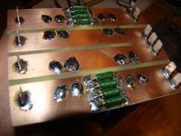
Is it really cost effective to make your own heatsinks from aluminum blocks compared to purchasing an extrusion? I would think the raw material costs of just an aluminum block large enough to make a heatsink from would cost more than a commercial unit. Yes you can make them any size you may want but unless you are also making custom sized enclosures is it cost effective. I'm just thinking of the time to do a setup on a mill and the cutting time plus the cost of materials let alone your own labor.
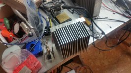
It's definitely cheaper purchasing extrusions than manufacturing your own from billet unless you have access to cheap metal. I inherited a couple tons of aluminum when a customer of ours shut down an airplane wing manufacturing facility and asked us to dispose of some of their moulds. It's very monotonous machining fins as well unless you have a CNC machine. It is cost effective and fast making heat sinks out of stacked sheet metal though. Fly cutting does a wonderful job of finishing them quickly too. I've done a little research into the anodizing. It looks pretty painless. That's my next experiment.
http://sound.westhost.com/articles/diy-heatsink.htm
Attachments
Could you make fins in an aluminum block quickly with a drill press and a cross slide vice using the right bit?

Could you make fins in an aluminum block quickly with a drill press and a cross slide vice using the right bit?
You would destroy the drill press quickly. The bearings aren't designed to be side loaded. It's even tricky to do on a milling machine depending on the depth of the fin. The fin will vibrate as you are cutting leaving a poor finish.
Updated Kypton-V2 "sansui" ....
Thimios responded with a 😱 ,when he heard it in it's "classic form".
Bimo had the same reaction ... and kept asking me to design it. 😕
Removed - The super-pair and the bad sound.
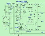
Added -
- C13 - lead comp.
-The anti-parallel diodes in the first stage.
- R34 for servo "settling".
- BJT OR FET at input. Perfect with every Jfet I tried !
Fet's are different ....
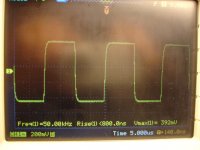
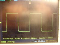
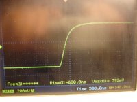
.007%- 20hz/ .001%- 200hz/ 3ppm 500-10Khz/ 14ppm-20K
Package below.
OS
Thimios responded with a 😱 ,when he heard it in it's "classic form".
Bimo had the same reaction ... and kept asking me to design it. 😕
Removed - The super-pair and the bad sound.
Added -
- C13 - lead comp.
-The anti-parallel diodes in the first stage.
- R34 for servo "settling".
- BJT OR FET at input. Perfect with every Jfet I tried !
Fet's are different ....
.007%- 20hz/ .001%- 200hz/ 3ppm 500-10Khz/ 14ppm-20K
Package below.
OS
Attachments
Last edited:
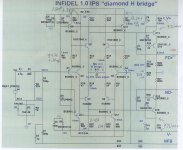
Infidel v1.0
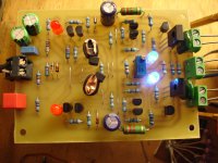
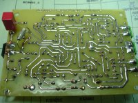
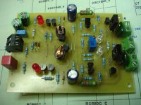
Now it's alive!
Now it's alive!
Attachments
-
 DSC08256.JPG544.7 KB · Views: 205
 -
 DSC08257.JPG603.8 KB · Views: 210
 -
 DSC08258.JPG575.6 KB · Views: 213
 -
 DSC08259.JPG584 KB · Views: 273
 -
 DSC08255.JPG556.8 KB · Views: 206
 -
 DSC08254.JPG538.2 KB · Views: 207
 -
 DSC08253.JPG569.7 KB · Views: 222
 -
 DSC08252.JPG542.1 KB · Views: 234
 -
 DSC08250.JPG551.6 KB · Views: 309
 -
 DSC08251.JPG548.6 KB · Views: 409
Last edited:
That's a nice square response! Similar to my MF80 project, which uses MOSFETs as OPS 🙂 (See here..)
Last edited:
Now it's alive!
VAS current is high and it's not controlled by the trimmer...
What is the control chanching R17?
Attachments
R28/R29 "steal" VASVAS current is high and it's not controlled by the trimmer...
What is the control chanching R17?
current from the Cascodes , lowering those values (trimmer) will
lower the cascode current with more (I) for the LED's.
You WON'T be able to see this on Q13/Q16 emitter resistors. To
calculate the cascode current , subtract the LED forward current
from the current you measure on R24/R31.
Another way I told still4given is to place a 10R between IPS/OPS PD+
and measure VAS current directly.
The full range on R28 should be 10K=3.8ma to 100k 5.8ma. Your CCS's
are running "hotter" 1.8ma .... you should have 4.5 - 6.5ma range.
Edit - the RED LED Vf must be 1.8v (newer red's).
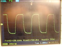
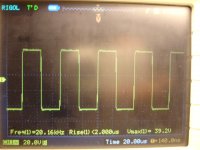
R17 - "rbridge" .... you can reduce this to 5 to 10R and get 300khz
square-waves that look like your 50khz ones !! 😱
If you want to "max" this one out - 10-12pf for C7-8 and 5R for R17.
This will give 4.2mhz CLG and 1000V/uS slew with a little overshoot.
PS - this will "flat out" beat most forum CFA's and most definitely the VFA's.
You can even degenerate the diamond (and bridge) Re's - 27-33R and get
>>1Kv/us (1.2Kv/us is the record).
OS
Last edited:
You joined the Sansui "cult" , Thimios ?? Ha , HA...😀
PS - I did consider embellishing the original design would detract from the
"classic experience". You could go one step further and use a JFET 1st stage input pair.
I will re-design "V" with diodes + JFET option.
OS
OS, I wonder how Kypton-V sound with Hawksford cascode VAS instead single transistor VAS....
OS, I wonder how Kypton-V sound with Hawksford cascode VAS instead single transistor VAS....
Oscillates even better than with the Baxandall. 🙁 Too many (poles & zero's).
You need some Ccb for such a high Z 2 stage IPS.
Baxandall and the Hawksford both work VERY well for the Infidel. I
chose the Hawksford because it's faster. 😀
OS
Oscillates even better than with the Baxandall. 🙁 Too many (poles & zero's).
You need some Ccb for such a high Z 2 stage IPS.
Baxandall and the Hawksford both work VERY well for the Infidel. I
chose the Hawksford because it's faster. 😀
OS
Should it reduce gain of high frequency at VAS like vzaichenko did with TMC compensation?
The credit did not come in yet - hope it comes soon, I will re-order 6800uF caps right away then. What are those "+ per channel"? Let me know the value and the quantity - easy to add them there 😉
Hi, Val. I shipped the returns out monday@noon. You should see credit
when it reaches Minnesota.
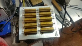
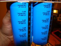
What I meant was any 35mm snap-in. Most 6800's are 35 X 50mm and
8200's are 35mm X 60mm. I have over 100mm (between Wilhelm's aluminum
plates). I can fit 12 of these = 98400uf .... all for <10$ each. 6800's = 81Kuf
6-7$ each.
Even as this is less than the 4 - 33k's , 3 pair paralleled banks have lower ESR. Ripple would be reduced. 🙂 Much easier to source and afford.
OS
OS,
Are you still thinking of developing a power supply for all these different power amps? I imagine a universal unit won't work with the variations in numbers of output devices but perhaps that isn't true?
Are you still thinking of developing a power supply for all these different power amps? I imagine a universal unit won't work with the variations in numbers of output devices but perhaps that isn't true?
Should it reduce gain of high frequency at VAS like vzaichenko did with TMC compensation?
I don't know about Val's version , but I was overcompensating to keep
the baxandall local FB loop from misbehaving. My probe shows the
superpair to have a 15mhz peak. Thimios made a 19mhz oscillator out of it. 😀
Without the superpair , I could "unleash" the high gain of this IPS.
A smaller C3/C6 (last kypton V2 schema) gave me 2mhz CL unity gain and
excellent gain margin at 20K. THD dropped to single digit ... better than
with the superpair. I could even push UG further with the new C13 (lead
comp.) to gain some stability margin.
PS - this amp can't be fully evaluated for stability by probing
the main FB loop ! It's a "freak"
In the real world listening tests ... dropping the superpair caught thimios's
attention instantly. 2 post saying "please" 😱😱 fix this amp !! 😀
Baxandall = good for LIN's and CFA's (apex's amps - kypton C). NOT for
this one.
Why fix what is not broken ? I ask ....
OS
OS,
Are you still thinking of developing a power supply for all these different power amps? I imagine a universal unit won't work with the variations in numbers of output devices but perhaps that isn't true?
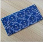
Just get a cheap multi cap PCB for 35mm snap-ins from ebay. 4 caps per
channel for 2 pair , 6-8 caps per channel for the monster.
You can adjust total capacitance - 4700u , 6800u , even 10KuF(per cap).
All are 35mm w ..10mm leads and will fit.
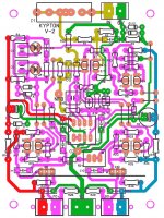
I intend to etch my own cap PCB's - real simple with quick connects.
OS
Attachments
Although it may look strange, my prototypes with Baxandall + Hawksford (with the tube at the input) feel very good. Soldered the second channel, hooked up OPS - just works. Situation with Terry's build is not so easy, but my two channels don't show any problem. What's going on? 😕 🙂 It behaves very close to simulation... 🙄
Although it may look strange, my prototypes with Baxandall + Hawksford (with the tube at the input) feel very good. Soldered the second channel, hooked up OPS - just works. Situation with Terry's build is not so easy, but my two channels don't show any problem. What's going on? 😕 🙂 It behaves very close to simulation... 🙄
Would you try BJT version?
I still do not understand clearly how tube behave 😀
It look like tube have high capacitance "base - collector" (if BJT, what it called for tube?).
Attachments
Would you try BJT version?
I still do not understand clearly how tube behave 😀
It look like tube have high capacitance "base - collector" (if BJT, what it called for tube?).
For the tube it would be "grid - plate" 🙂
It's somewhat closer to jfet than to bjt... high impedance, high linearity, low gain and - you're right - rather high input capacitance.
I will try bjt version a bit later - prototyping the "clean CFA" now 😉
- Home
- Amplifiers
- Solid State
- Slewmaster - CFA vs. VFA "Rumble"