I have a few of these handsome NOS transistors, which I belive are meant for power supply and voltage regulator etc, but I think there are better IC choices for that at the moment.
So what about an audio amplifier? I have a bit of experience turning a power tube into a class A single ended amp, but no experience whatsoever with solid-state, could the forum suggest me something? using an output transformer and arranging the transistor in a sort of triode class A ? or finding a complementary NPN pair, or pushpull.... I'm aiming at 10 or maybe 15 watts. No idea where to begin
Maximum collector power dissipation (Pc), W: 75
Maximum collector-base voltage |Ucb|, V: 60
Maximum collector-emitter voltage |Uce|, V: 40
Maximum emitter-base voltage |Ueb|, V: 30
Maximum collector current |Ic max|, A: 50
Maksimalna temperatura (Tj), °C: 85
Transition frequency (ft), MHz: 0.04
Collector capacitance (Cc), pF:
Forward current transfer ratio (hFE), min: 25
An externally hosted image should be here but it was not working when we last tested it.
So what about an audio amplifier? I have a bit of experience turning a power tube into a class A single ended amp, but no experience whatsoever with solid-state, could the forum suggest me something? using an output transformer and arranging the transistor in a sort of triode class A ? or finding a complementary NPN pair, or pushpull.... I'm aiming at 10 or maybe 15 watts. No idea where to begin
An externally hosted image should be here but it was not working when we last tested it.
Maximum collector power dissipation (Pc), W: 75
Maximum collector-base voltage |Ucb|, V: 60
Maximum collector-emitter voltage |Uce|, V: 40
Maximum emitter-base voltage |Ueb|, V: 30
Maximum collector current |Ic max|, A: 50
Maksimalna temperatura (Tj), °C: 85
Transition frequency (ft), MHz: 0.04
Collector capacitance (Cc), pF:
Forward current transfer ratio (hFE), min: 25
Hmmmm very interesting.
I'm not likely to be much help as in not an expert in any way, but isn't the Ft going to limit the useable gain a little too much?
Maybe some of the smart guys here will say some better things?
Maybe a buffer of some sort, with a very low gain? 3 dB or thereabouts? In order to keep the audio bandwidth... Maybe even 0dB gain.
Again, i am only guessing. Id imagine the stage feeding these transistors would be doing most if not all the gain.
Last edited:
Your big big problem with germanium is heat. Wheras a silicon device will happily run at 60 to 80 C, anything much above about 45C will see the leakage current go through the roof.
So germanium and Class A in high powers don't really go together.... but I have an idea.
Why not have a try at making the classic JLH69 10/15 watt amplifier using your PNP germanium outputs. All you do is reverse the polarity of the supply, swap NPN for PNP and vice versa and reverse the electrolytics.
Attachments
Maybe good for a couple of watts in single ended class A, from maybe a 12-15 volt supply. Don't try to go higher, they are really only menat for LOW voltages. I had some similar devices and tried to build a push pull class B out of them. I was only using about a 30V single rail, and the output pair went into second breakdown and died within a few minutes - and the output stage didn't even have time to warm up. After all the trouble I went to to re-drill the heat sinks for TO-36's. Rebuilt with "modern" 2SB407's and it worked perfectly for years. But those were made for audio amps.
The very first amp I made used a pair of AD149's and it gave excellent service. From memory it was pretty much a classic 5 transistor Lin configuration, AC coupled running on about 35 volts I think. It sounded excellent when stacked up against my parents B&O system.
Good tips, so far, keep it conservative. I'm aware of the temperature issues with these transistors but come on 75W plate dissipation!! 😀 jk.
I bet it's going to be a lot of trial and error.
I bet it's going to be a lot of trial and error.
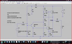
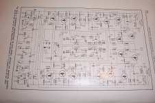
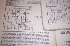
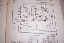
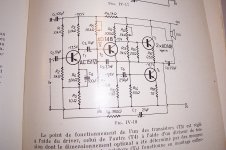
At home I have some books with schematics of Ge amplifiers, I'll post one or two pics in the evening.So what about an audio amplifier? I have a bit of experience turning a power tube into a class A single ended amp, but no experience whatsoever with solid-state, could the forum suggest me something?
But a Ft of 40KHz(!) won't get you very far: the sound will be soft, oh so soft, just like a vintage AM tube radio....
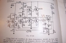
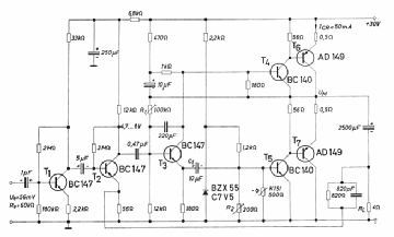
Here are some examples, ranging from 10W to 45W.
Your transistors would have no difficulty coping with this kind of power.
Your transistors would have no difficulty coping with this kind of power.
Attachments

Here are some examples, ranging from 10W to 45W.
Your transistors would have no difficulty coping with this kind of power.
Wow ! Templar parchments ?
😀
You must be joking: they are much more precious than that: all of my teenage years in six screenshots!Wow ! Templar parchments ?
😀
Perhaps transformer coupled with 12v ?
I built many amps with that line up.
Transformers still available on fleabay.
Kevin
I built many amps with that line up.
Transformers still available on fleabay.
Kevin
The fifth one looks interesting with the TR7 and the bias network. The basics of the main amp are very like the one I mentioned I built (the AD149 job) although only the output were Geraniums in mine 😀
Here are some examples, ranging from 10W to 45W.
Your transistors would have no difficulty coping with this kind of power.
Good stuff, the only caveat is the availability of NPN germaniums on some of those circuits, so perhaps I should look into something with Si in the first and intermediate stages. I've seen such schematics using AD149 as power outputs although I can't find many of them.
The History
I believe that part was originally developed by Delco Radio for GM factory car radios in the early 1960's. Mainly to replace all tube designs with their very unreliable mechanical switching HV power supplies.
Ive opened junked car radios and seen a few designs exactly like this, lots -o- big transformers and chokes with a single TO-36 mounted on a heat sink. http://www.updatemydynaco.com/HistoricDocuments/DelcoCarRadioAmp1962.pdf
EDIT> yes Delco manufactured the 1st Germanium power devices themselves . Motorola followed http://www.33audio.com/enter/data/Delco1963.pdf
Last edited:
I reckon the only value for Ge power parts like those are to folks who repair car radios for 'auto restoration purists'.
It's a 50 amp transistor after all, which I imagine was pretty massive back then. AD149 is only rated at 3.5 amps but has a far more usable (if still modest) fT of 500 kHz. And I always thought types with 3 MHz were pretty slow dogs...But a Ft of 40KHz(!) won't get you very far: the sound will be soft, oh so soft, just like a vintage AM tube radio....
fT of 40 kHz means that beta is down to 2 at 20 kHz. Full hFE is only available up to <2 kHz at best. A voltage reg really is the best kind of application for something like this.
An amplifier with 3 MHz outputs would typically employ a GBW of about 1 MHz (or less). Here we'd be looking at little more than 10 kHz, i.e. not even the whole audible spectrum even with no voltage gain. Maybe there is some nested feedback trickery that would allow circumventing this, but else...
Last edited:
And it's probably 50 amps at up to 1 or 2 volts VCE, and may be good for an amp at 12V. If they are anything like the Delcos I've fooled around with years ago.
So germanium and Class A in high powers don't really go together
As pointed out most car radios from the late 50's through the mid 60's used a germanium class A output stage. It was usually a 2N174, and Delco made their own devices. The 50's radios used space charge tubes that operated with 12 volts on the plate for all stages except audio output. Around 1960 the radios used all germanium transistors. Silicon took over in the mid 60's.
Incidentally Delco maintained their own device fab well into the 90's and bought the mask rights to the Motorola MC6802 microprocessor and made more of those chips than Motorola did.
The transistor you show in the picture was made by Motorola in 1974. A 50 amp germanium transistor was not common, ever. It would have been expensive, and far to big for a car radio which ran at about 1 amp. The low Ft makes it unsuitable for audio use.
It could have been used in a power supply, but most commercial power supplies would have used multiple smaller devices for cost reasons.
1974 is well after the peak of germanium devices. I know that Motorola kept at least one germanium line running for "special" parts well into the 70's, so these parts went to someone who needed them for an old design. My guess would be a servo or motor control system for something military.
Incidentally the popular Motorola HT220 hand held walkie talkie used germanium audio output devices originally made by RCA. Mot had to start making their own devices for the 220 in the mid 70's because RCA was shutting down germanium.
The most popular germanium transistor for home HiFi was the 2N2147. A quick Google search for that number will bring up the transformer driven totem pole circuit that everybody used in the 60's. It may be of use here, but the frequency response will be limited by Ft. I built many guitar amps with that circuit. The driver transformer can be wound by trifilar winding 3 identical strands on the bobbin of a small heater transformer (6.3 volts 1 amp).
My curiosity got the best of me so I did some digging. The 2N1522 was used in military two way radio systems as a step up switching transistor. This replaced the mechanical vibrator or dynamotor type supply used before transistors this big were available.
A pair of these were used in a cross coupled multivibrator switching arrangement driving a transformer to step up 12 or 28 volts to several hundred volts to operate tube radio equipment. Their low VCEsat is why germanium was preferred over silicon for this application. Typical operation is a saturated or cutoff type switch in the 1 to 2 KHz region.
The 2N1522 has both a NSN (Navy) and an FSN (all military).
- Status
- Not open for further replies.
- Home
- Amplifiers
- Solid State
- Germanium power transistor 2n1522