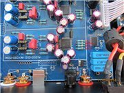
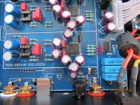
Hi Valeri100,
I'm sure that on the DAC PCB there's pins for mclk, dck, lrck, etc... This xmos module has to be connected using I2S, it would be stupid not to anyways. So there should be a GND, the USB data pins + the 5v and the rest of the pins should be I2S related... Just a wild guess of course... 😀
Ciao!
Do
Hi Pinnocchio,
This Xmos board is connected via Spdif. It simply converts Usb to Spdif and not to I2S. I am sure about it.
Hi Pinnocchio,
This Xmos board is connected via Spdif. It simply converts Usb to Spdif and not to I2S. I am sure about it.
Wow... That really a bad design... 😡
Anyways, I can still use my WaveIO, it has SPDIF out.
Thanks
Do
This DAC signal is on the bus i2s.USB-SPDIF-I2S-4399. Can be mounted so that odoemene all from the receiver.View attachment 436147
Oh very nice!
Thanks
Do
Hi Valeri,
thanks a lot for your confirmation 😉
Thanks for the help... I just got a little upset why they have not used the I2S for that part... 😀
Ciao!
Do
Hi Pinnocchio
I see from your signature that you have Aleph 5 amplifier. How do you like its sound? I am currently building Aleph J mono blocks which has very similar schematic. What is your best/favorite amplifier?
thx for an answer in advance
I see from your signature that you have Aleph 5 amplifier. How do you like its sound? I am currently building Aleph J mono blocks which has very similar schematic. What is your best/favorite amplifier?
thx for an answer in advance
pinnocchio: no idea, I bought it just for better selling purposes, I've always used toslink connection where I do not have to deal with jitter at all, why would u need I2S connection if u got all standard connections available? u can always use I2S to spdif convertor if neccessary
I use ordinary convertor him sound better than SPDIF Asus STX.
¡ºÄ§Òôʦ¡»Êý×ÖÊä³ö ÔÉúUSB3.0 Êý×Ö½çÃ桾Êý×ÖÔ´USB¡¿XMOSתÅÌ-ÌÔ±¦Íø
¡ºÄ§Òôʦ¡»Êý×ÖÊä³ö ÔÉúUSB3.0 Êý×Ö½çÃ桾Êý×ÖÔ´USB¡¿XMOSתÅÌ-ÌÔ±¦Íø
Hi Pinnocchio
I see from your signature that you have Aleph 5 amplifier. How do you like its sound? I am currently building Aleph J mono blocks which has very similar schematic. What is your best/favorite amplifier?
thx for an answer in advance
I don't want to pollute this thread so I will PM you later about this.
Ciao!
Do
Hi Guys.
I think the board converts I2S to SPDIF because this way the input can be selected with the AK4113/AK4118 receiver. The receiver doesn't accept I2S.
I2S is considered better, at least for short distances, because clock and data signals are separated. This way it's less sensitive for data related jitter.
kukynas: Toslink isn't a cure for jitter unfortunately. Jitter is a clock timing problem, which can even be worse when using toslink. Optical link requires the signal to be converted at both sides, which can cause further errors. It depends still on the receiver IC if/how these errors (jitter) are corrected. Toslink has the advantage however, to electrically isolate source(transport) and receiver (DAC), reducing noise transfer.
Regards,
Nino
AK118A TVDD voltage
In reference to the newer vesion of dual AK4399 using AK4118A as receiver, I found the PCB is using 3.3V for TVDD that the datasheet shows 3.3V is the absolute minimum voltage to be used. In many cases, the datasheet specifies 5V for TVDD.
What is TVDD? What is it for?
What are the consequences in using the minimum voltage (3.3V) rather than 5V for TVDD?
Hi Nino,
you are right, I was referring to connection itself rather then transport and receiver capability to handle internal jitter...
you are right, I was referring to connection itself rather then transport and receiver capability to handle internal jitter...
I think the TVDD pin is more tolerant than the other psu pins. Typical it operates on 3.3V, max. on 5.5V, min on DVDD (which is also 3.3V in this case).In reference to the newer vesion of dual AK4399 using AK4118A as receiver, I found the PCB is using 3.3V for TVDD that the datasheet shows 3.3V is the absolute minimum voltage to be used. In many cases, the datasheet specifies 5V for TVDD.
What is TVDD? What is it for?
What are the consequences in using the minimum voltage (3.3V) rather than 5V for TVDD?
Datasheet recommends 3.3V for TVDD (input buffer supply).
If you mean CD transport with CDT, then it depends on that transport where to tap the 4 wires from. The wires can connect to the 2xAK4399 PCB, but you're no longer able to use spdif/toslink/usb via spdif. See lomonosoff''s post: http://www.diyaudio.com/forums/digi...ng-dual-x2-ak4399-dac-lcd-53.html#post4043835
I2S connection
Hi NinoSimona,
Thank you very much. I missed the post.
My CDT is CDPro2 and has I2S output. Does this mean I can skip the receiver and connect the I2S output directly to the 4 resistors and a GND signal? In this manner, I think I have to lift the resistors from the PCB and connect the two corresponding resistors together. Am I right?
Yet, from my manual, I saw my CDT has different names in output pins. Does they corresponds to the names here
MCLK (MCLK)
SCLK (BCK)
Data (SDOUT)
LRCK (LRCK)
GND (GND)
The connection is short (about 50 cm). What kind of cable should I choose? Ribbon cable or Cat5?
Regards,
- Status
- Not open for further replies.
- Home
- Source & Line
- Digital Line Level
- ebay:Weiliang Dual X2 AK4399 DAC with LCD

