Ok , here we go
I am pretty proud of this one😀
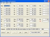
Version 3
Still a very simple design, and this one is 100% compatible with HR's segments, chambers and ports so this curve should be close enough to what you will get in real life 🙂 Someone out there could still try to Akabak it if they want, it should be a lot easier with this one because it is relatively straightforward compared to the last version i uploaded ...
I plan to make this my final version of the ML-Transflex for the LAB15 special..
- Great output
- Low group delay
- Excursion stays below 13mm at a full 58v (600w)
- driver is easily accessible without the use of a removable panel
- efficient use of cabinet volume, no wasted space
- simple single fold design, easy build, all straight panels, no angles
- acoustically shortened path by use of a mass loading constriction, which is a long vent at 50% of the main pipe's area, velocity should not exceed 20 m/s in worst case scenario in the real world.(calculated by multiplying the velocity at mouth (*2 for the 2:1 mouth/port area ratio)
- Very affordable driver $134 shipped, get em while they last!
- Woofer's motor is located in the mouth (the high velocity end of the pipe) which maximizes cooling of the voicecoil ! Which equates to reduced thermal compression when used at high SPLs for extended periods of time.. Longer life, and more output!
- well balanced bass output, just the right amount of damping.
I will get a sketch drawn up for this thing tomorrow , dimensions are very similar, i just have to extend one dimension to allow for a few more liters of internal volume ...
Wow - this just keeps getting better. I have one Lab 15 now, I may have think about getting a 2nd.
Last edited:
Just threw in some values for the sws 12d4 for that same kind of alignment (as the lab 15) and it appears that it can be within a dB or so of the pipe and is a little flatter, now just need to see size improvement (and if it's worth). Trying sws15d4.
Scratch that I forgot to change ND to TH, back to drawing board.
Scratch that I forgot to change ND to TH, back to drawing board.
Last edited:
David,
I was just trying to express an observation ... Small changes in QES cause big changes in QTS, and big changes in QMS cause relatively small changes in QTS ... I suppose that is where i was going with that 🙂
I am learning the math little by little ...
When i was a child in school i despised mathematics, it is not surprising that "How many apples does little Johnny have left?" wasn't interesting to me in the slightest, i was bored to tears and hopelessly uninspired with it
 , but now that i am older and i am into fun nerdy stuff like speaker cabinet design I am just enthused as heck about the practicality and usefulness of these mathematical formulas... I dare say it is even kinda fun to learn and utilize them! I never would have thought ....... Me?? no way 😛
Perhaps that would be a good strategy to get children in school to be more interested in mathematics, show them how it can be employed to be creative and make something useful, practical, tangible ..... Show them how mathematics is the underlying code in the "matrix" of our universe!
Software thats readily available, free, and user friendly like WinISD and Hornresponse were gateway drugs into this world of design for me .....


Good stuff man..
Last edited:
It's over 100% efficient, beat that
Haha, just joking but at the impedance spike with 8 sws 12d4 pipes corner loaded as I've outlined the acoustic conversion efficiency claims to be over 100%, I'm guessing in reality it would stop at 100%. Can you imagine 148 dB down to 35? Of course you wouldn't need that much, I'd stop at 2 placed in a corner and if I had more they would be spread out and middle wall located for flatness. That would be enough to do an IMAX easily 🙂, how does corner loading get affected by high ceilings/large rooms?
Haha, just joking but at the impedance spike with 8 sws 12d4 pipes corner loaded as I've outlined the acoustic conversion efficiency claims to be over 100%, I'm guessing in reality it would stop at 100%. Can you imagine 148 dB down to 35? Of course you wouldn't need that much, I'd stop at 2 placed in a corner and if I had more they would be spread out and middle wall located for flatness. That would be enough to do an IMAX easily 🙂, how does corner loading get affected by high ceilings/large rooms?
The "corner loading" does not change, but room modal response changes with size and shape, the modes being integers of the wavelengths reflected by the room boundaries (or not reflected from room door and window openings), causing peaks and dips at various locations depending on the various room dimensions.how does corner loading get affected by high ceilings/large rooms?
Getting notes together for Saba's SWS12 build
Saba ,
That Lab box version 3 is dialed in very specifically for the LAB15 , and is not well suited at all for your SWS12...
I have tried putting the SWS12 into a few of the sims that were intended for the Lab15 specials, and it didn't really accommodate the Alpine 12 as well as i would like to see.. I was able to shrink it down to a small size in the range of 90 to 100 liters with very flat response in that design which is nice & compact, but the output just fell a little bit short ..... It might be an alright choice if your preference is to have it as compact as possible but its not the ideal choice if you are looking for maximum output ... With another 30 to 50 liters i can get 3 to 4 more decibels of output with a cabinet more specifically tuned for your SWS 12 (if you are willing to accept an increased cab size)..
What i know so far when it comes to your driver and requirements:
Just threw in some values for the sws 12d4 for that same kind of alignment (as the lab 15) and it appears that it can be within a dB or so of the pipe and is a little flatter, now just need to see size improvement (and if it's worth). Trying sws15d4.
Scratch that I forgot to change ND to TH, back to drawing board.
Saba ,
That Lab box version 3 is dialed in very specifically for the LAB15 , and is not well suited at all for your SWS12...
I have tried putting the SWS12 into a few of the sims that were intended for the Lab15 specials, and it didn't really accommodate the Alpine 12 as well as i would like to see.. I was able to shrink it down to a small size in the range of 90 to 100 liters with very flat response in that design which is nice & compact, but the output just fell a little bit short ..... It might be an alright choice if your preference is to have it as compact as possible but its not the ideal choice if you are looking for maximum output ... With another 30 to 50 liters i can get 3 to 4 more decibels of output with a cabinet more specifically tuned for your SWS 12 (if you are willing to accept an increased cab size)..
What i know so far when it comes to your driver and requirements:
- 35hz FB can be accomplished with a 6 foot (non expansion) path if a strategic internal port or constriction of between 1/3 and 1/2 main path area is employed (keeping velocity within safe range). Port length has been increased in order to compensate for it's large-ish area, and everything will still fit into the same box
- Shortened path length should allow for the single fold box to not exceed your 39 inch height limitation ..... Your SWS12 driver seems to work well enough with as much as 45cm offset if needed so if the box needs to made even shorter a double fold design might be an option if you want a cube-ish box with larger footprint ...I have been contemplating a simple double fold inspired by the Karlsonator,(but without expansion) ...
- I am Mostly simming in OD and TH modes .. When in TH mode this driver seems to prefer a minimal tapped effect.. In OD mode there is no tapped effect so this driver looks great in those QWP sims with about 20% to 30% increase in the box's internal volume (compared to a small ML-Transflex) ....
- Compound alignments (with quarter wave loading for the low tuning, and either helmholtz or quarter wave for the upper tuning) look absolutely STUNNING with your SWS12 driver, but of course they have to be made a little larger ..... So there is that compromise again .... Just yesterday i came up with something that i think could be considered 8th order (with the creative use of another chamber & port) and it is my favorite so far for your SWS12 ..
I'm interested in this compound alignment and the "compact box" to a little lesser degree. Size constraints really depend on the customer as I'm all for efficiency but some venues have a certain size inset into a wall that they "have to fit in", at this point though I'm not selling to them so I'm open to whatever gets the most output per dollar (hopefully maintaining 1 sheet limitation of plywood for cost reasons). In reality my 39 inch height limit was so that I could stack a lot of cabs in my car but if 4 larger cabs get the job done (compared to 6 or 8 smaller) height can go as long as 60, given that the depth is kept to about 16 or so.
Currently I really like the 46 inch straight pipe's "response curve" as it is 121 dB +-1 dB 35-100 Hz. So if anything can get this kind of output or perhaps a little more that would be awesome.
I agree, the Lab 15 "style" of design doesn't play nice with the alpine, I tried too.
PS driver arrived today, seemed unopened (the driver) but was likely a return unit that never was used due to repackaging of tape -- there was no manual, luckily I don't need one.
Last edited:
The "corner loading" does not change, but room modal response changes with size and shape, the modes being integers of the wavelengths reflected by the room boundaries (or not reflected from room door and window openings), causing peaks and dips at various locations depending on the various room dimensions.
I've heard that with tall enough rooms I.E. >50 feet tall you no longer get corner gain as it acts like it is outside... Has anyone else heard this?
Corner loading in AkAbak assumes no ceiling and no other walls except 2 sides and 1 floor. Mathematically, corner loading is an octant of a sphere (4pi steradians) open space on ground is half a sphere or 2pi steradian. On floor against wall is 1pi steradian and corner is 1/2pi steradian. You will get enhanced loading in a room with low ceilings but that is a room mode effect and not "corner" loading. In other words corner loading enhances 8x vs a speaker suspended from a wire by a helicopter way above the ground.
EXPERIMENTAL DESIGN 8TH ORDER QW TAPPED? SWS12
SABA,
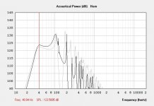
Take a look at this, and load these inputs into your HR but be sure to switch to the "rear vented" option under main/tools/Chamber Type . This is another creative use of additional chambers & ports.
It is still a rough concept and we would still need to figure out how to make it all fit into a cabinet , but the output is great for a 35hz box with a 12" woofer ... The bandwidth is limited (only goes to 100 or so) but that is fine for your apps right? The peak up top is also more subdued compared to the rest of the curve than the other compound designs i was looking at .... Two of these cabs hits 130db in halfspace at 38hz at full power or over 140db in 1/8th space (with corner placement)! Thats only 1000w input total and about 300 liters combined net (150L per cab)
Similar SPL performance to the LAB15 special in it's highly fine tuned cab , and the cab volume is about the same as well , but these are 12s instead of 15s! ON 200W LESS POWER! AND CONSIDERABLY LESS MONEY SPENT!!! pretty neat😀
I know we are comparing apples to oranges here to some degree, but how do you like them apples? 😉
hehehe
Ok, I am back to work on the LAB15 (special) ML-Transflex V3 sketch now.
SABA,
Take a look at this, and load these inputs into your HR but be sure to switch to the "rear vented" option under main/tools/Chamber Type . This is another creative use of additional chambers & ports.
It is still a rough concept and we would still need to figure out how to make it all fit into a cabinet , but the output is great for a 35hz box with a 12" woofer ... The bandwidth is limited (only goes to 100 or so) but that is fine for your apps right? The peak up top is also more subdued compared to the rest of the curve than the other compound designs i was looking at .... Two of these cabs hits 130db in halfspace at 38hz at full power or over 140db in 1/8th space (with corner placement)! Thats only 1000w input total and about 300 liters combined net (150L per cab)
Similar SPL performance to the LAB15 special in it's highly fine tuned cab , and the cab volume is about the same as well , but these are 12s instead of 15s! ON 200W LESS POWER! AND CONSIDERABLY LESS MONEY SPENT!!! pretty neat😀
I know we are comparing apples to oranges here to some degree, but how do you like them apples? 😉
hehehe
Ok, I am back to work on the LAB15 (special) ML-Transflex V3 sketch now.
Attachments
Last edited:
SABA,
Take a look at this, and load these inputs into your HR but be sure to switch to the "rear vented" option under main/tools/Chamber Type . This is another creative use of additional chambers & ports.
It is still a rough concept and we would still need to figure out how to make it all fit into a cabinet , but the output is great for a 35hz box with a 12" woofer ... The bandwidth is limited (only goes to 100 or so) but that is fine for your apps right? The peak up top is also more subdued compared to the rest of the curve than the other compound designs i was looking at .... Two of these cabs hits 130db in halfspace at 38hz at full power or over 140db in 1/8th space (with corner placement)! Thats only 1000w input total and about 300 liters combined net (150L per cab)
Similar SPL performance to the LAB15 special in it's highly fine tuned cab , and the cab volume is about the same as well , but these are 12s instead of 15s! ON 200W LESS POWER! AND CONSIDERABLY LESS MONEY SPENT!!! pretty neat😀
I know we are comparing apples to oranges here to some degree, but how do you like them apples? 😉
hehehe
Ok, I am back to work on the LAB15 (special) ML-Transflex V3 sketch now.
voltage a bit high, 16.32 mm at peak displacement. You are simulating with over 700 watts to the driver at points. Kinda cheating 🙂. Took the voltage down to 65 (more reasonable, close to xmax displacement).
Come to think of it 58 volts to a lab 15 is 800+, something isnt adding up.
voltage a bit high, 16.32 mm at peak displacement. You are simulating with over 700 watts to the driver at points. Kinda cheating 🙂. Took the voltage down to 65 (more reasonable, close to xmax displacement).
Come to think of it 58 volts to a lab 15 is 800+, something isnt adding up.
It is based upon RE
The Eminence's RE is actually kinda high for a 4ohm Pro driver, thats more like the RE that many car audio drivers use .. Technically it's impedance will be over 4 ohms and you have to compensate for that somehow if you are comparing two different drivers to see which one actually performs best ... A big discrepancy of RE between drivers can really throw off comparisons ...
When i click on Hornresponse's "Eg" i will rarely put exactly 8 or 4ohms into the lower field because I enter a figure based upon a multiplier applied to the RE so i am getting a closer to fair comparison ..
A really good example is your SWS12 driver, with the two coils in series we are getting an RE of 7 ohms and that is well above the typical RE of most 8ohm Pro drivers which can have RE figures as low as 4.8 , but more commonly in the range of 5 to 6.5...
Last edited:
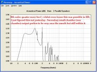
Here is an output comparison at XMAX for the (darker) 8th order hybrid, and (lighter) straight pipe. Keep in mind that I haven't looked into possible compression issues with the 8th order, the pipe shouldn't have any. In general it appears to be 1.5 dB more down low and 3 dB up high (~80). We'll see about air velocities once it turns into a drawing, now it's just specs and I imagine Matthew has a generic sketch in mind but none of the dimensions are set yet.
Attachments
It is based upon RE
The Eminence's RE is actually kinda high for a 4ohm Pro driver , thats more like the RE that many car audio drivers use .. Technically it's impedance will be over 4 ohms and you have to compensate for that somehow if you are comparing two different drivers to see which one actually performs best ... A big discrepancy of RE between drivers can really throw off comparisons ...
When i click on Hornresponse's "Eg" i will rarely put exactly 8 or 4ohms into the lower field .... I enter a figure based upon a multiplier applied to the RE so i am getting a closer to fair comparison ..
A really good example is your SWS12 driver , with the two coils in series we are getting an RE of 7 ohms and that is well above the typical RE of most 8ohm Pro drivers which can have RE figures as low as 4.8 , but more commonly in the range of 5 to 6.5...
While that may be true, hornresp takes the actual impedance of the cab into account when you double click on the graph and hover over specific frequencies, and it clearly states the electrical input power at that frequency. Maybe I'm overly cautious as it is highly unlikely that we would drive sine waves at full power anyways.
What's great in this design is the impedance spike around 45 Hz means that the voice coil will be dissipating very little heat during "intense 45 Hz centered content" I.E. Most club music. Therefore the output will be primarily limited by XMAX, besides at around 35 and 75 Hz.
Last edited:
While that may be true, hornresp takes the actual impedance of the cab into account when you double click on the graph and hover over specific frequencies, and it clearly states the electrical input power at that frequency. Maybe I'm overly cautious as it is highly unlikely that we would drive sine waves at full power anyways.
Yes , Hornresponse takes the impedance that you enter in the "Eg" popup window into account , and thats the problem really ... 60volts at 4 ohms is considerably more wattage than 60v at 8ohms because there is more current draw at 4ohms .... Unfortunately many drivers that are labeled "8 ohm" are actually anywhere from truly 8 ohms impedance to as high as 10.5 ohms ...
Same with 4 ohm woofers , even though they are labeled "4ohm" they could have an impedance of almost 6ohms if the RE is approaching 4 ..
Last edited:
I really think it is one of the reasons why car audio subs (even good ones) haven't been taken too seriously (even though interest has been picking up) in serious apps like portable DJ or clubs , etc .... For example: when comparing a DVC car sub with two 4 ohm voice coils in series (7+ ohms RE) with another driver that has a much lower RE figure like a PA driver then the car audio sub appears to underperform in simulations , when in fact it may have the potential to perform just as well or even better ....
Using the multiplier method allows a fair comparison can be made.
Using the multiplier method allows a fair comparison can be made.
Last edited:
Hey matthew how "constricted" is the 8th order design you're toying with? What kind of velocities are we talking about, and how big is the duct/port?
I will list some examples of how RE can be all over the place for a supposedly "4 ohm" driver ...
Eminence Impero 15C = RE of 3.11ohms
Alpine SWE-10S4 = 3.85 ohms
POWERBASS S-10T = 3.2 ohms
ElectroMavin EM-TL2501A-4= 3.2 ohms
Eminence Legend BP102-4 = 2.7 ohms !
Celestion Neo 5" (at PE) = 3.2 ohms
Eminence Kappa Pro-15LFC = 3.34 ohms
Eminence Lab12c = 3.11 ohms
Eminence Legend 620H = 3.94 ohms
Jensen MOD6-15 = 3 ohms
......
Now we cannot be expected to believe that all of the above drivers are exactly 4ohms in impedance can we? Of course not, because they aren't ...
So i use a multiplier to compensate and even-out the playing field as much as i can , its not a perfect solution but it helps quite a bit .. Just like the LE hack i was talking about .... Not perfect , but it gets us closer ...
Hey matthew how "constricted" is the 8th order design you're toying with? What kind of velocities are we talking about, and how big is the duct/port?
It could be built either constricted or not .... The mass loading just allows us to physically shorten the line to some extent while keeping the same acoustic tuning .... If we stick to no more than a 1/3 area pinch we should be fine when it comes to velocity,, a 1/2 area squeeze is even more ideal, i managed that in the most recent LAB15 cab 😀 (but it was a little trickier to make everything fit properly.. .)
I will list some examples of how RE can be all over the place for a supposedly "4 ohm" driver ...
Eminence Impero 15C = RE of 3.11ohms
Alpine SWE-10S4 = 3.85 ohms
POWERBASS S-10T = 3.2 ohms
ElectroMavin EM-TL2501A-4= 3.2 ohms
Eminence Legend BP102-4 = 2.7 ohms !
Celestion Neo 5" (at PE) = 3.2 ohms
Eminence Kappa Pro-15LFC = 3.34 ohms
Eminence Lab12c = 3.11 ohms
Eminence Legend 620H = 3.94 ohms
Jensen MOD6-15 = 3 ohms
......
Now we cannot be expected to believe that all of the above drivers are exactly 4ohms in impedance can we? Of course not, because they aren't ...
So i use a multiplier to compensate and even-out the playing field as much as i can , its not a perfect solution but it helps quite a bit .. Just like the LE hack i was talking about .... Not perfect , but it gets us closer ...
Whether or not the manufacturer specifies it as "4 ohms" and the resulting comparison discrepancy -- the driver will see the amount of power that hornresp says and thus I error on the side of caution as I don't want any voicecoils burning up. Anyway I'm interested to see what this looks like.
- Home
- Loudspeakers
- Subwoofers
- New sub design? Constricted Transflex, simple build (series tuned 6th order)