I don't think so. The SPDIF is 24bit width and for DoP one needs to send 32bit data, doesn't it?
Due to reports of such issues, plus frying BBBs, to boot, I've pretty much decided that I'm going to have to have a power and peripheral management Arduino, handling a standby battery backup, long-term power loss shutdown, start-up, and to top it off, no hot-plugging at all. For example, a permanently connected internal HDD for core/WORM media storage, and then only allowing the network for anything else.
...
Great, keep us posted blood. I have not seen any such system though (but I did not search really).
The udoo board would be perfect because it has the arduino included. I am using the Najda digital XO and WaveIO, ideally one switch should control all the devices (less boxes, easier start, improved WAF/kidsAF 😀). But probably the botic cannot be adapted. We are getting too much platforms now 😕
Jean-Louis
I don't think so. The SPDIF is 24bit width and for DoP one needs to send 32bit data, doesn't it?
DoP is 24 bits as well,
http://dsd-guide.com/sites/default/files/images/USB_DSDviaPCM_1v0.jpg
DSD64 ... 64*44100 bits per second per channel ... 16 DSD bits in 24 DoP frame ... 64*44100/16 = 176400Hz per DSD channel
Therefore using single SPDIF link there would possible to transfer just single DSD64 channel.
Therefore using single SPDIF link there would possible to transfer just single DSD64 channel.
You can only make DoP over SPDIF work if you transmit at double rate. So that two samples are combined to create one. The would take special decoding. Honestly though.... why do it? Just get the raw DSD closer to the target DAC. There is really no need to do DoP.
I'm investigating various UPS/auto-shutdown options for the BBB.
Does anyone know the correct way to power down the BBB via external trigger?
I was guessing that some form of I2C communication would be required, but I found this -
BeagleBone in a Board Farm - Texas Instruments Wiki
Does anyone know the correct way to power down the BBB via external trigger?
I was guessing that some form of I2C communication would be required, but I found this -
BeagleBone in a Board Farm - Texas Instruments Wiki
So this is a simple case of a GPIO pulldown. Is this all that's required?To simulate the power button a relay controlled 100 ohm pull-down can be connected to PWR_BUT/P9.9.
linuxfan:
- there is generic mailing list for such quesitons: BeagleBoard.org - Forums
- answer is also in the documentation file BBB_SRM.pdf
- pull the P9.9 down for 8 second (not more, otherwise it will restart)
- there is generic mailing list for such quesitons: BeagleBoard.org - Forums
- answer is also in the documentation file BBB_SRM.pdf
- pull the P9.9 down for 8 second (not more, otherwise it will restart)
Thanks miero. I found good information on that BeagleBoard forum.
For anyone else concerned about power outages, there are 2 good options:
i) BeagleBone Power Cape - full external power management ($60 + battery)
BeagleBone Power Cape | AndiceLabs
or ii) connecting a LiPo or Li-ion battery directly to the BBB, utilising the onboard TPS65217C power management
Uninterruptible Power Supply (UPS) for BeagleBone Black – a DIY Project | Asterisk for BeagleBone Black
Just back from a business trip - Miero and I are taking a final critical look at the cape. We have already noticed a few things that need attention.
For example, uFL connectors needed to be relocated because of mechanical conflict on the bottom side. Also adding a few more explicit headers for some functions like ADC or a rotary encoder(for input).
I will have some pics to post very soon. I want to get consensus that I have hit all the highlights before I send this off. 🙂
Hi Russ, when you are ready to post the pictures I think it would be useful to recap on the key features as the thread is getting unwieldy now...
Ray
Yes indeed.
I may just go ahead and add a spot to connect a battery with NTC lead as presented here:
Uninterruptible Power Supply (UPS) for BeagleBone Black – a DIY Project | Asterisk for BeagleBone Black
Then we could just supply a 4 pin female power header for the BBB and a male header of the bottom of the Botic. Then one could choose to use it not, if using it one need only connect the appropriate battery to a JST header on the cape.
Thoughts?
Sounds good to me Russ.
On the 'list of key features' theme, I was looking to see if the Botic has isolated sections but couldn't locate it; could be that it isn't there or could be because I'm just seeing trees?
Ray
On the 'list of key features' theme, I was looking to see if the Botic has isolated sections but couldn't locate it; could be that it isn't there or could be because I'm just seeing trees?
Ray
Not currently planning on isolators - because they really should not be required with the re-clocking scheme. Also there is just only so much space without making the board overly complicated/expensive for no clear advantage to the end result.
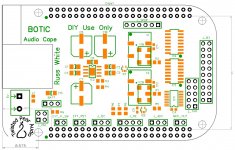
Notice I added the bridge to the power management header(TP5-TP-8) and added the parts need to attach the appropriate battery. This should give you a couple of hours of standby time with 1950ma. I think we could also pretty easily do some sort of shutdown trigger.
Fantastic...! 🙂Notice I added the bridge to the power management header(TP5-TP-8) and added the parts need to attach the appropriate battery. This should give you a couple of hours of standby time with 1950ma. I think we could also pretty easily do some sort of shutdown trigger.
Eagerly await by the minute. 😉
Many thanks again Guys!
I may just go ahead and add a spot to connect a battery with NTC lead
...
Then we could just supply a 4 pin female power header for the BBB and a male header of the bottom of the Botic. Then one could choose to use it not, if using it one need only connect the appropriate battery to a JST header on the cape.
Thoughts?
OK, thanks. Ideally, I believe the BBB, itself, should provide a JST connector plus resistor & cap.Notice I added the bridge to the power management header(TP5-TP-8) and added the parts need to attach the appropriate battery. This should give you a couple of hours of standby time with 1950ma.
So it's commendable that you have made provision for battery backup on your cape, effectively making up for a shortcoming of the main board's implementation!
Yes, there's already been some work done in this area. I'm still searching, but at this stage I see that there's a dedicated kernel module for the PMIC: tps65217I think we could also pretty easily do some sort of shutdown trigger.
and there's a patch for this module which hard-codes a power shutdown -
https://groups.google.com/forum/#!topic/beagleboard/umJLdbn4pkA
but this seems a bit ugly.
It would be better to query the PMIC's power status from userspace with a daemon script, then issue the shutdown command ("shutdown -P now") under defined circumstances. These circumstances could then be modified to the user's preference.
"Yes, there's already been some work done in this area."
Botic demo image shuts the BBB down when:
- power button is (shortly) pressed
- "shutdown -h now" is called
It should send also power event on AC status change (there is code in the kernel driver).
Botic demo image shuts the BBB down when:
- power button is (shortly) pressed
- "shutdown -h now" is called
It should send also power event on AC status change (there is code in the kernel driver).
For an "power event on AC status change", BBB should have in some ways, access to an AC line/rail. There is not the case so far, as BBB was designed. It was adapted the cape to fix this "missing link"?
To detect the AC power fail, and manage this by hardware/software it will be the most elegant way to solve this problem... Then an enough large capacity it may be enough... if the shout-down sequence do not take too long time...
To detect the AC power fail, and manage this by hardware/software it will be the most elegant way to solve this problem... Then an enough large capacity it may be enough... if the shout-down sequence do not take too long time...
- Home
- More Vendors...
- Twisted Pear
- Building an open embedded audio applicance.