Just a quick question. I thought I fixed my amp but NO....
Now have to change some NPN Mosfets out...
Question is, I presume they are output and input as, one reads something and another something else...
One is: C4467
Then under that it reads 40 Y (looks more like a "V"
Then: A1694
Under that: 50 P
I've found a few Mosfets, but they read 00 Y, not "40 Y" just 2 zero's
Is that right, or?
Attachments
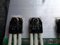
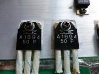
They aren't MOSFETS, they are bipolar transistors. 2SA1694 is the PNP part, and 2SC4467 is the NPN part. The other markings (40 Y etc) are probably date codes.
hi
the parts you are dealing with here are not MOSFETs, they are Bipolar junction power transistors.
2SC4467 NPN type and 2SA1694
the letters signify the hfe (gain) groups
0 = 50 - 100
P = 70 - 140
Y = 110 - 180
i would go with either P or better Y types making sure that they are both of the same kind in the same channel of your amp.
Those are indeed bipolar transistors.
If they are not short circuit they are most likely all right.
It will blow fuses if they were faulty.
I would check all the switching as amps of the period used to have switches that got dirty and intermittent easily.
I have a home made transistor matching device that I made in the 1970s and it still works all be it a manual unit. It is the first knockings if a curve tracer and could be vastly improved now OP amps are cheaper.
I can post the circuit if you are interested.
Last edited:
Hi there, so, what voltage do I look for? For example, I looked on Farnell UK | Electronic Components | Electronic Parts and they go into so much detail, temp and a few other things, bit lost.
By the way, 4 of them are leaking, where they should be Open Line, they ain't...Rather, just stuck in the on position, looks like I might have to replace them all 🙁 4 are labeled A1694 and the other 4 C4467
Bob, Y = 110 - 180, wont matter with voltages?
Refugee, sure, I'd like to see it...
By the way, 4 of them are leaking, where they should be Open Line, they ain't...Rather, just stuck in the on position, looks like I might have to replace them all 🙁 4 are labeled A1694 and the other 4 C4467
Bob, Y = 110 - 180, wont matter with voltages?
Refugee, sure, I'd like to see it...
If they are turning on when power is applied the problem is with the driver stage and not the output transistors.
hi Samurai
what is the make and model of the amp? i would need a cicuit diagram to advise further
what is the make and model of the amp? i would need a cicuit diagram to advise further
Hi bob, they seem not to make a service manual, but it's a img stage line sta-500
I'm just waiting for a e-mail from them to see if they can give me a service manual...
I'm just waiting for a e-mail from them to see if they can give me a service manual...
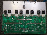
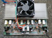
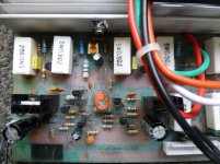
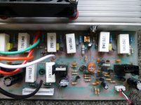
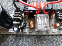
Here are the pictures bob 🙂
Just a little extra, what it was! doing, was the power protect would always come on when it was powered up, then if I removed the internal speaker terminals from the power board it wouldn't go into protect (it would for a split second on power up) then back to normal. I tested if there was any dc voltages, none, no resistance either in the speaker terminals, yet, as soon as I put the multimeters needless into the + and - of the external speaker terminals (with the internal amp terminals not connected) it would go into protect again.... So odd! no burn marks anywhere! all the caps read fine, except 2 that are weird, 100uf, but read as 125...
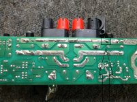
The ONLY thing I could see was, you see under the circuit board for the speakers (on the power board) not the main terminals, the far outside one's, the bit of solder that is touching the other solder and to the left it is not touching, is that a short? Or meant to be like that?
Just a little extra, what it was! doing, was the power protect would always come on when it was powered up, then if I removed the internal speaker terminals from the power board it wouldn't go into protect (it would for a split second on power up) then back to normal. I tested if there was any dc voltages, none, no resistance either in the speaker terminals, yet, as soon as I put the multimeters needless into the + and - of the external speaker terminals (with the internal amp terminals not connected) it would go into protect again.... So odd! no burn marks anywhere! all the caps read fine, except 2 that are weird, 100uf, but read as 125...
The ONLY thing I could see was, you see under the circuit board for the speakers (on the power board) not the main terminals, the far outside one's, the bit of solder that is touching the other solder and to the left it is not touching, is that a short? Or meant to be like that?
hi there
the bottom of the board where you indicate looks ok.
with the amp connected through a series test lamp on the mains 60 watt about right. all connections connected on output /protect board nospeaker no load.
power up and measure DC voltage from ground to to output of the amp before the output board this point is at the junction of the power resistors the big white ones,5watt 0.5Rr. looks to be the white and orange wires. check both outputs what are the readings?
Last edited:
That is a small offset on the speaker terminals.
You need to find out what that little preset adjustment does.
It should set the offset to zero and that should stop it tripping.
The power transistors should be all right.
You need to find out what that little preset adjustment does.
It should set the offset to zero and that should stop it tripping.
The power transistors should be all right.
Hi Bob, I measured between the ground and outputs as you said, I got these results in the continuity test.
Powered on: - 510 (both channels)
Powered off: The measurement increases to over 1000
I don't have a test lamp 🙁
Powered on: - 510 (both channels)
Powered off: The measurement increases to over 1000
I don't have a test lamp 🙁
Refugee, do you mean the 2 orange screws on the amp board?
They work by, counter clockwise is less? thus clockwise is more?
They work by, counter clockwise is less? thus clockwise is more?
I'm stupid, if I adjust these presets, so they read 0, then, it shouldn't clip anymore?
I read that these bios adjustment screws go bad a lot of the time
I read that these bios adjustment screws go bad a lot of the time
Xsamuraix , I suggest you follow Burbcek´s advice only; Refugee1 spews nonsense and will make you burn your amp.
And he asked for *voltage* readings between speaker out and ground, not "continuity" .
And building a series lamp is easy and cheap, no excuse for not making it.
Just one example:
Light Bulb Limiter
And in case you didn´t get it: DO NOT TOUCH THOSE BIAS AND OFFSET TRIMMERS.
And he asked for *voltage* readings between speaker out and ground, not "continuity" .
And building a series lamp is easy and cheap, no excuse for not making it.
Just one example:
Light Bulb Limiter
And in case you didn´t get it: DO NOT TOUCH THOSE BIAS AND OFFSET TRIMMERS.
510 whats?Hi Bob, I measured between the ground and outputs as you said, I got these results in the continuity test.
Powered on: - 510 (both channels)
Powered off: The measurement increases to over 1000
I don't have a test lamp 🙁
over 1000 whats?
Are you measuring Volts, or Amperes, or Ohms, or Farads, or Henries?
"Don't have test lamp."
Then build one.
- Status
- Not open for further replies.
- Home
- Design & Build
- Parts
- NPN Mosfets