I looked the formula up again and it looks like i used the wrong one. Do you have the book
"Switching power supply design by Pressman"
I think the formulas on pages 73-74 are the correct ones.
"Switching power supply design by Pressman"
I think the formulas on pages 73-74 are the correct ones.
i have found some formules for calculating the output inductance. may i apply this to my center tap primary and full bridge at the output push pull converter.If you use a choke, the stress on the diodes will be substantially reduced, even if the inductance is too small to allow for PWM control
Help for Full-Bridge Push-Pull Converter
~ 4mH should be sufficient for PWM control
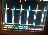
thanx so much now i have the signals like the topology show how they should be. i have ossilations only which will be easy to snub them at least i hope so.
my drains are now sharply going up and down with the gate signal.
~ 4mH should be sufficient for PWM control
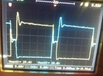
it is snubbed and here are the drain voltages.
Attachments
Toyer, here is a screenshot of Pressman’s inductor calculation. Also from what i have found, no two books agree on how to calculate inductors. So do not worry about the small differences you will find.
Lo = 0.5VoT/Ion
“im plannin to have 150 watt power at 310 vdc” = .484A = Ion
310vdc = Vo
“sg3526 running at 100 khz. so my frequency on transformer is 50 khz” = .00002 Second’s = T
Lo = 0.5 * 310vdc * .00002 Second’s / .484A = 6.4mH
Lo = 0.5VoT/Ion
“im plannin to have 150 watt power at 310 vdc” = .484A = Ion
310vdc = Vo
“sg3526 running at 100 khz. so my frequency on transformer is 50 khz” = .00002 Second’s = T
Lo = 0.5 * 310vdc * .00002 Second’s / .484A = 6.4mH
Attachments
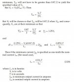
thank you. so i need to put a dummy load for getting ten percent of Io nominal current. which means i have to dissipate 16 watt. if i put bigger inductance so the power i have to dissipate for minimum current will decrease.Toyer, here is a screenshot of Pressman’s inductor calculation. Also from what i have found, no two books agree on how to calculate inductors. So do not worry about the small differences you will find.
Lo = 0.5VoT/Ion
“im plannin to have 150 watt power at 310 vdc” = .484A = Ion
310vdc = Vo
“sg3526 running at 100 khz. so my frequency on transformer is 50 khz” = .00002 Second’s = T
Lo = 0.5 * 310vdc * .00002 Second’s / .484A = 6.4mH
Waveforms depend on the control (or lack of control) strategy. They are normal in both cases.thanx so much now i have the signals like the topology show how they should be. i have ossilations only which will be easy to snub them at least i hope so.
my drains are now sharply going up and down with the gate signal.
If you need a fixed transformation ratio, a PWM-less, inductorless topology is acceptable. With no inductor at all, the diodes will experience some stress, but that can be alleviated with small inductors.
If you want a full control, a large enough inductor is mandatory, and it has to withstand the max peak current without saturation and have acceptable dynamic losses when storing/releasing energy, which means a part of respectable size.
Depends on where your priorities are, but you are fortunate in one way: your basic architecture is healthy, works well and can adapt itself to whatever regime you impose (within reasonable limits)
thank you. so i need to put a dummy load for getting ten percent of Io nominal current. which means i have to dissipate 16 watt. if i put bigger inductance so the power i have to dissipate for minimum current will decrease.
Elvee knows a lot more than i do, let's see what he says.
I think the way it work's is if you are unregulated you will not need a minimum load.
If you are using voltage regulation mode you do not need a minimum load.
If you are using current regulation mode then you need a minimum load.
Yes you can increase the inductance for lower minimum current. The inductor will be larger and more expensive and the speed of regulation will be slower.
your basic architecture is healthy, works well and can adapt itself to whatever regime you impose (within reasonable limits)
I really disagree with that statement, because
- the typicall push-pull converters are NOT short-circuit proof
- they require an output inductor
- they require a minimum load
- lossy snubbers
- hard switching MOSFETs
You may argue, that trillions of that type work in car radios and car audio boosters. Yes they do, but after my experience with a harman kardon car booster blowing on power-on, I would not rely on this strongly: What I found was not amusing.
Why building push-pull pwm-converters today, instead of LLC-converters?
- these can be made inherently short-circuit proof
- they require no output inductor
- they require no minimum load
- no lossy snubber
- soft-switching MOSFETs
- less stress on MOSFETS, better efficiency
And yes, you can control them with SG3825, TL494... as well.
The only thing really different is the transformer.
Best is a gapped ferrite core with a split bobbin for loose coupling, toroids not recommended.
my first goal here was just to get the unregulated stable dc. so now i will design a feedback loop and i will implement it to the controller. so i will get a regulated dc output, and also an overcurrent and low voltage protection for the curcuit.Waveforms depend on the control (or lack of control) strategy. They are normal in both cases.
If you need a fixed transformation ratio, a PWM-less, inductorless topology is acceptable. With no inductor at all, the diodes will experience some stress, but that can be alleviated with small inductors.
If you want a full control, a large enough inductor is mandatory, and it has to withstand the max peak current without saturation and have acceptable dynamic losses when storing/releasing energy, which means a part of respectable size.
Depends on where your priorities are, but you are fortunate in one way: your basic architecture is healthy, works well and can adapt itself to whatever regime you impose (within reasonable limits)
here i have a question. lights bulps can get like 10-15 times more current then it rated current when they first energized.
so now with my converter im using uf4007 diodes which are rated for 1A. if i put a light bulb like 75 watts at the beginning it can take like 5-6 A of current. so how to protect the diodes ? with an over current curcuit i can protect the diodes but in this way i will not energize a 75 watts light bulp.
I really disagree with that statement, because
- the typicall push-pull converters are NOT short-circuit proof
- they require an output inductor
- they require a minimum load
- lossy snubbers
- hard switching MOSFETs
You may argue, that trillions of that type work in car radios and car audio boosters. Yes they do, but after my experience with a harman kardon car booster blowing on power-on, I would not rely on this strongly: What I found was not amusing.
Why building push-pull pwm-converters today, instead of LLC-converters?
- these can be made inherently short-circuit proof
- they require no output inductor
- they require no minimum load
- no lossy snubber
- soft-switching MOSFETs
- less stress on MOSFETS, better efficiency
And yes, you can control them with SG3825, TL494... as well.
The only thing really different is the transformer.
Best is a gapped ferrite core with a split bobbin for loose coupling, toroids not recommended.
i think he is talking about just for this curcuit.
and you are talking about push pull topology.
in my case im not experienced to talk about the topologies. im just learning and implementing them for now. later on i will learn rthe other topologies and will see which one is suitable for which application.
Last edited:
If you use an open-loop PWM control, but that would be silly: either you work completely without, or you implement a full PWM control.thank you. so i need to put a dummy load for getting ten percent of Io nominal current. which means i have to dissipate 16 watt. if i put bigger inductance so the power i have to dissipate for minimum current will decrease.
A half-way solution brings you the disadvantages of both.
With a regulation, you only need to waste very little power in a bleeder, because the regulation will continue to operate in discontinuous mode
Nobody ever claimed thatI really disagree with that statement, because
- the typicall push-pull converters are NOT short-circuit proof
No, if no control is required- they require an output inductor
Idem- they require a minimum load
More or less, but if these points are understood, they pose no particular problem- lossy snubbers
- hard switching MOSFETs
That is the topology the OP has selected. I try to help him solve his current problems, not engage in some kind of proselytism like you doWhy building push-pull pwm-converters today, instead of LLC-converters?
This can be more or less true, but of course there are other aspects: the design is much more demanding on the passives, both in terms of accuracy and stress. The peak currents are higher, etc.- these can be made inherently short-circuit proof
- they require no output inductor
- they require no minimum load
- no lossy snubber
- soft-switching MOSFETs
- less stress on MOSFETS, better efficiency
There are no free lunches in engineering
Implementing feedback makes the whole thing much more complex.my first goal here was just to get the unregulated stable dc. so now i will design a feedback loop and i will implement it to the controller. so i will get a regulated dc output, and also an overcurrent and low voltage protection for the curcuit.
here i have a question. lights bulps can get like 10-15 times more current then it rated current when they first energized.
so now with my converter im using uf4007 diodes which are rated for 1A. if i put a light bulb like 75 watts at the beginning it can take like 5-6 A of current. so how to protect the diodes ? with an over current curcuit i can protect the diodes but in this way i will not energize a 75 watts light bulp.
Regarding the light bulbs, I would be concerned about the MOSfets, not the diodes: they can easily take huge non-repetitive peak currents, but the transistors would need to be hugely overdimensioned to do the same
I uttered my opinion, which is based on experience with both topologies.
Since I got into LLC converters, I prefer this type of converters, no way back to pp for me.
Besides the reasons I gave it may be a matter of taste too what looks "nice" or "ugly" to the developer, depending on personal preferences and knowledge.
Anyway threads like this show, that pwm controlled push-pull is not easy at all for DIYers. So why not have a look at other topologies?
Just my 2 c😉
If you use an open-loop PWM control, but that would be silly: either you work completely without, or you implement a full PWM control.
A half-way solution brings you the disadvantages of both.
With a regulation, you only need to waste very little power in a bleeder, because the regulation will continue to operate in discontinuous mode
Nobody ever claimed that
No, if no control is required
Idem
More or less, but if these points are understood, they pose no particular problem
That is the topology the OP has selected. I try to help him solve his current problems, not engage in some kind of proselytism like you do
This can be more or less true, but of course there are other aspects: the design is much more demanding on the passives, both in terms of accuracy and stress. The peak currents are higher, etc.
There are no free lunches in engineering
Implementing feedback makes the whole thing much more complex.
Regarding the light bulbs, I would be concerned about the MOSfets, not the diodes: they can easily take huge non-repetitive peak currents, but the transistors would need to be hugely overdimensioned to do the same
with 165watt load fets are getting hot. and the snubber resistors.
fets have 2x2x1 aliminium in dimensions on them for cooling and a fun is working. fets are getting like 90 degree celcius. and also the snubbers resistors are getting rerally hot.
irfz44
Last edited:
with 165watt load fets are getting hot. and the snubber resistors.
fets have 2x2x1 aliminium in dimensions on them for cooling and a fun is working. fets are getting like 90 degree celcius. and also the snubbers resistors are getting rerally hot.
irfz44
2x2x1 cm
Not really surprising: taking the efficiency into account, the average input current is 16A, and the peaks are even higher, that is sufficient to make the FETs hot.with 165watt load fets are getting hot. and the snubber resistors.
fets have 2x2x1 aliminium in dimensions on them for cooling and a fun is working. fets are getting like 90 degree celcius. and also the snubbers resistors are getting rerally hot.
irfz44
Check the waveforms, to see if you can relax the snubbers and if the FETs are properly driven
Not really surprising: taking the efficiency into account, the average input current is 16A, and the peaks are even higher, that is sufficient to make the FETs hot.
Check the waveforms, to see if you can relax the snubbers and if the FETs are properly driven
fets are driven 120 nanosec rising and 110 nanosec falling time. too slow?
what do you thing that a 12 volt to 310 volt dc 150 watt converter efficiency. i mean what percent of efficiency we can say that this is good for this push pull converter.
How much current are you drawing from the battery?
Does a 16A slowblow fuse hold? 20A??? 25A? 30A?...
Does a 16A slowblow fuse hold? 20A??? 25A? 30A?...
80% efficiency is probably a reasonable guess. I tried to figure out why your fets are getting hot but i had trouble reading the spec sheet, maybe someone could help. This is what i came up with.
165w output / .8 efficiency = 206w
I = 206w / 12vdc input = 17A
Each fet supplies ½ the current
17A / 2 = 8.5A per fet
Your schematic shows an IRFZ44N, the spec sheet says 17.5 milli ohms Rds on. Looking at the spec sheet for Rds on vs Id i can not find a chart. I do see one for junction temperature vs Rds on. With a guess of 60 Deg C to 100 Deg C that would give a Rds on between 1.25 ohms and 1.6 ohms.
P = I^2 x R
P = 8.5A^2 x 1.25 ohms
P = 72.25 x 1.25 ohms = 90w minimum??? Thats crazy, for a fet that is advertized as 17.5 milli ohms.
Does anyone see what the problem is?
Attachments
- Status
- Not open for further replies.
- Home
- Amplifiers
- Power Supplies
- push pull converter 12Vdc to 310 V dc drain voltages problem,im confused