Hi,
I have a question on a zobel network arrangement. Even though my question seems to sounds stupid, but it's be skeptical to me for a long time.
I wonder what's the different if I...
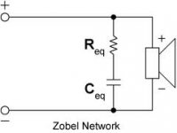
1. place a resistor on the positive side and a capacitor on the negative side. (image 1)
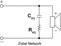
2. place a capacitor on the positive side and a resistor on the negative side. (image 2)
I've heard that the component's placement would affect to the sound in the sense that the sound would received the characteristic from a component which placed near the negative side.
Is this a real story ?
I have a question on a zobel network arrangement. Even though my question seems to sounds stupid, but it's be skeptical to me for a long time.
I wonder what's the different if I...
1. place a resistor on the positive side and a capacitor on the negative side. (image 1)
2. place a capacitor on the positive side and a resistor on the negative side. (image 2)
I've heard that the component's placement would affect to the sound in the sense that the sound would received the characteristic from a component which placed near the negative side.
Is this a real story ?
Attachments
OK, first there is no "positive or negative" here, it's AC. The plus and minus signs only give a common connection scheme so all of the drivers in the system will be in phase with each other, they could be marked "0 and 1" or anything else. Because it's AC, and the cap and resistor are wired in series it makes no difference at all which way you connect them.
Mike
Mike
I guess the subject is best discussed in this thread: http://www.diyaudio.com/forums/lounge/234829-funniest-snake-oil-theories.html
Trying to rationalize from what you say, then...I've heard that the component's placement would affect to the sound in the sense that the sound would received the characteristic from a component which placed near the negative side.
Is this a real story ?
In the next half-cycle (AC) the opposite should happen?! No? 😀
It DOES make a difference which way you wire them. At radio frequencies you would always place a physically large coil or capacitor with its outer layer connected to the earth plane. Corresponding to the first diagram.
This is to stop crosstalk and interference in the COMMON MODE. 😎
Whether it matters with the low frequencies and impedance of audio is debatable, but you might as well get it right. 🙂
This is to stop crosstalk and interference in the COMMON MODE. 😎
Whether it matters with the low frequencies and impedance of audio is debatable, but you might as well get it right. 🙂
You talk about Radio Frequencies... I doubt that the effects will be (near) significant at audio frequencies upto 20 Khz...It DOES make a difference which way you wire them. At radio frequencies you would always place a physically large coil or capacitor with its outer layer connected to the earth plane. Corresponding to the first diagram.
This is to stop crosstalk and interference in the COMMON MODE. 😎
Whether it matters with the low frequencies and impedance of audio is debatable, but you might as well get it right. 🙂
You talk about Radio Frequencies... I doubt that the effects will be (near) significant at audio frequencies upto 20 Khz...
I didn't say it would be significant necessarily, but it is always good to follow good engineering practise. Sod's Law and The Law of Unexpected Consequences say that things often go wrong in surprising ways in engineering. 😀
The consequence of sloppy earthing and bird's nest construction in audio is that components can behave as radio aerials and pick up noise, or cause instability in an amplifier. I have heard a gramophone loudly pick up Radio 2 from the long wave.
Star earthing is another sound radio technique, and John DeVore always uses it in his speakers. Does it matter? Well, it doesn't cost anything to get it right. 😎
What does it mean in speakers construction (just in general)? Are all the legs connected to the same point as to have the same impedance?! 😕Star earthing
Well, there was this other diyAudio member that would just pick up the Radio (in the London region) every time he would set up is PA for events. I can't remember if his cables where balanced or unbalanced. The problem was on the side of the speakers, anyway... the guest speaker would not be the one the crowd was there for. 🙄
The negative rail is not actually the same as ground, which you'd reckon is a copper spike stuck in your back garden. It's just a reference point. Most amplifiers are not grounded at all, they actually float. Think of a battery radio, and you realise there is no ground at all. 🙂
Star grounding is connecting all the return feeds to the same point. In a speaker it means all the return wires from the drivers and the shunts of the filters and the negative input of the speaker go to the same point. The filter inputs and the speaker input all start from the same point too.
Star earthing matters greatly in amplifiers, where huge currents can flow along smallish PCB tracks and produce voltages which cause crosstalk and noise.
There is a problem with unbalanced systems in that the amplifier has a different star earth. You just hope the cable to the speaker doesn't interfere.
Biwiring is really taking the star earth back to the amplifier output. I just reread what John DeVore said about star grounding and why he doesn't biwire. He may have been being a bit elusive.
See a series filter has no possibility for biwiring and star earthing is trivial. Interview with Troels Gravesen at the same site, BTW, very interesting. 😀
BTW, just realised I use star earth and ground interchangeably. Confusing isn't it? LOL
Last edited:
And when there is no outer layer?...................you would always place a physically large coil or capacitor with its outer layer connected to the earth plane. .............
in speaker crossovers I usually prefer the zobel resistor connected to ground
but this might be influenced by other components near by
I usually hear a difference
and expect interaction with other components is the reason
maybe a high frequency zobel on amp output is a different matter
but since we are in multiway speakers ...
but this might be influenced by other components near by
I usually hear a difference
and expect interaction with other components is the reason
maybe a high frequency zobel on amp output is a different matter
but since we are in multiway speakers ...
I never regarded any of the speaker connections as being "ground"... there is far too much (several meters) cable connecting it to the amp (and it's ground). As far as I am concerned loudspekers are connected to amplifiers via antenna.😀in speaker crossovers I usually prefer the zobel resistor connected to ground
And when there is no outer layer?
You are referring to exotic "low inductance" style capacitors I suppose. 4 times bigger, due to the more complex construction, aren't they? It still applies. My own notion would be that physically larger components would be more affected than tiny ones since it's a question of the capacitor radiating energy to nearby components.
I'm always amazed how Zobels on tweeters outpunch their weight. Say 7.5R and 0.68uF on most 0.05mH tweeters. The sim often shows almost no effect, but you can hear them easily.
I'm guessing it's the phase of the amplifier load that is most affected by the Zobel. Since negative feedback is affected by phase, it matters. 😎
FWIW, an amplifier output Zobel is often around 10R and 0.1uF. It maintains high frequency stability. The inductance of a typical regular speaker cable, which has a characteristic radio impedance around 100 ohms, is < 0.005mH. Resistance might be < 0.5R if you've chosen the right guage for the job. These sort of facts help you assess whether something is significant, I find.
Last edited:
Unlikely to be an amplifier misbehaving effect.
Much more likely to be a crossover seeing the correct load impedance effect.
Much more likely to be a crossover seeing the correct load impedance effect.
Unlikely to be an amplifier misbehaving effect.
Much more likely to be a crossover seeing the correct load impedance effect.
I wouldn't be so fast on that assumption. I'm sure there is an effect on the crossover and ferrofluid (if used) does something to tweeter impedance at high frequency too. But bipolar transistors are running out of current and open loop gain at 20Khz, and distortion increases as a result. This was a particular problem back in the 1960s when output transistors were poorer.
It's called slew rate distortion, and it's load dependent. Well above the crossover point, the crossover is becoming increasingly invisible if you think about it. It simply passes the signal unaffected. All that is left is the resistors and the increasingly inductive load of the standard sort of tweeter.
Should we care? It could be leprechauns on bicycles in the Zobel for all most people know. But, I'd be interested to know your experience with tweeter Zobels. They mostly affect the very top range I think we'd agree.
Last edited:
But, I'd be interested to know your experience with tweeter Zobels. They mostly affect the very top range I think we'd agree.
some years ago I used a zobel on a tweeter
I thought just like you it was a great 'invention'
later I found that its effect was that it compensated or 'adapted' to phase problems elsewhere in the speaker
and when dealing with those phase problems instead, the tweeter zobel only had negative effect when implemented
but right now I'm having some luck with my previously trashed DIY ribbon
the new improvement was using a C-core as autoformer
don't know, but maybe a transformer coupled ribbon as ad on super tweeter is also working like a zobel

- Status
- Not open for further replies.
- Home
- Member Areas
- The Lounge
- Resistor vs Capacitor placement in a Zobel network