Modeling is all well and good and I do a lot of it too, but I have not found predictions of distortion to be particularly accurate, although in truth the predictions tend to be lower than what I actually measure.
The result is counter intuitive to what I generally measure in direct comparisons of topologies with the 6SN7 which is precisely why I commented on it.
The result is counter intuitive to what I generally measure in direct comparisons of topologies with the 6SN7 which is precisely why I commented on it.
Hi,
The SRPP stage shows the lowest distortion figures when looking at a low value fixed load (< 5K).
Measured way back into the late Nineties by Dutch magazine "Audio&Techniek IIRC.
Mu followers should show lower distortion figures than SRPP as the top triode is optimized to isolate the bottom one coming closer to an ideal current source.
Ciao,")
The SRPP stage shows the lowest distortion figures when looking at a low value fixed load (< 5K).
Measured way back into the late Nineties by Dutch magazine "Audio&Techniek IIRC.
Mu followers should show lower distortion figures than SRPP as the top triode is optimized to isolate the bottom one coming closer to an ideal current source.
Ciao,
THD is a measured 0.03% 2nd harmonic only visible, as a whole circuit V1.2 at nominal MC cart input level including the particular SUT (Dynavector DV6/Z guts) from a 50 Ohm attenuator Rsource.
Input stage noise will dominate the rest given the gain structure (head amp concept).
Input stage noise will dominate the rest given the gain structure (head amp concept).
Hi salas/ all,
Updated to rev 1.2, fitted ft3 0.1uf caps and the caps Fran Kindly sent me, one had
15.743uf written on it
Latest measurement's.
B+ 268 vdc
165v checkpoint, left=146v, right 157v
190v checkpoint, both =172v
V2 left=4.88mA, right=4.79mA
V3=0.55ma both
V4 left=5.32mA, right=5.25mA.
HiFi news 300hz tone, measured left=2.6mvac, right=2.8mvac, from my grado gold cartridge, 4mv output I think.
How does it look?
Cheers, Ian.
15.743nF (about fifteen point seventy five nanoFarad) not uF, yes?
With HFNRR disc and the Grado you should be getting mVRMS in the hundreds scale and more when measuring the outputs. Which one 300Hz bias track you used with how many dB modulation?
Which type of IR LED you used? What is the voltage drop across that LED in circuit?
You may reduce distortion and noise by replacing the second SRPP with this circuit.
Will construct a model for V1.2 full circuit in LT spice and see. Its not done based on sim, simple CAD was used just for drawings and ballpark bias points predictions for changes after the bulk was done practically and auditioned in the box. 5-6dB loss with the SRPP is something not small though bcs it makes HMC carts quiet in this one, for MM maybe still OK. THD will be mainly a contribution of the first stage at below 1-2V RMS (normal for the total gain and use) second stage levels more likely. Thanks.
I don't mean to be adversarial, so I'm sorry if I came across that way earlier.
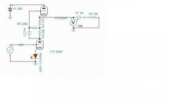
This works pretty well. Remarkably well, actually, compared to the simple SRPP using the same tubes. I have not optimized the resistor values.
It's putting out 14Vrms into 10kohms @ 0.179% distortion @ 1kHz. That's dang good in my opinion.
For a more realistic 1.34Vrms out, THD is 0.019%. Dang good for tubes with no loop feedback.
Replace the diode with a 133 ohm resistor and the THD drops to 0.010% for the 1.33Vrms output.
I don't think the diode does much, really.
And, just to be clear, I only use THD measurements in Spice as a guide. I don't expect these kinds of numbers in real life, I only use them as a guide for optimizing the circuit. My presumption is that the models and software I'm using are decently accurate, and that I can rely on the changes in THD (and S/N) as a guide.
I am not trampling on this circuit or disparaging the hard work that went into it. I merely found a sweet spot in the other SRPP circuit that looked great, but does not hold up for lower loads.
Attachments
Last edited:
It's putting out 14Vrms into 10kohms @ 0.179% distortion @ 1kHz. That's dang good in my opinion.
For a more realistic 1.34Vrms out, THD is 0.019%. Dang good for tubes with no loop feedback.
Replace the diode with a 133 ohm resistor and the THD drops to 0.010% for the 1.33Vrms output.
I don't think the diode does much, really.
V1.2 Mu output stage has 12K in the middle and 330R up and down, no LED. Can you run it for those values as your sim's ready so we know if its near or far to those figures with same models?
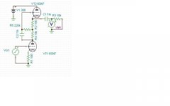
This is the best I can do with this circuit right now.
THD is 0.002% @ 1.3Vrms output into 10kohms @ 1kHz.
Gain is 25dB from less than 10Hz to about 70kHz.
S/N is 122dB @ 1kHz.
DC current is 9.11mA.
Really outstanding performance.
THD is 0.002% @ 1.3Vrms output into 10kohms @ 1kHz.
Gain is 25dB from less than 10Hz to about 70kHz.
S/N is 122dB @ 1kHz.
DC current is 9.11mA.
Really outstanding performance.
Attachments
Last edited:
V1.2 Mu output stage has 12K in the middle and 330R up and down, no LED. Can you run it for those values as your sim's ready so we know if its near or far to those figures with same models?
OK:
Gain is slightly less @ 1.27Vrms output into 10kohms.
THD is 0.010% for the same conditions.
Second harmonic is dominant, as is expected.
S/N is slightly lower at 117dB.
OK:
Gain is slightly less @ 1.27Vrms output into 10kohms.
THD is 0.010% for the same conditions.
Second harmonic is dominant, as is expected.
S/N is slightly lower at 117dB.
Ah, we cross posted. You already did. Not bad either even on a sim evaluation. Thanx.
P.S. About S/N when a small envelope valve is used in double the current and wattage between possible configurations I have seen noise going up with temperature in some occasions when signal wise was predicted better. Seen that in some 12AT7 & 12AY7 and a couple of trioded Russian pentodes in the past. When above 5mA. Metals and physics probably.
15.743nF (about fifteen point seventy five nanoFarad) not uF, yes?
With HFNRR disc and the Grado you should be getting mVRMS in the hundreds scale and more when measuring the outputs. Which one 300Hz bias track you used with how many dB modulation?
Which type of IR LED you used? What is the voltage drop across that LED in circuit?
Hi Salas,
typo, it is a 15nF cap not uF.
The LED is a Rodan HIRL5020 Infrared, RS part number 267-8396.
Are these the correct ones?
I measured 1.03vdc at V1 cathode and 0 on the ground side, both channels?
HFNRR I previously used the 300Hz Azimuth track.
News measurements with the Bias tracks.
+12dB
left in=3.7mv out=1.06v
Right=3.2mv out=1.00v
+14dB
left in=5.1mv out=1.47v
Right=4.5mv out=1.37v
+16dB
left in=6.4mv out=1.82v
Right=5.5mv out=1.68v
+18dB
left in=8.5mv out=2.31v
Right=6.8mv out=2.00v
Does this look ok??
Many Thanks
Ian
The IR Led is alright for 1VF (see if same L&R), the channel balance is alright, it gradually gains for left channel at the top velocity torture tracks not due to electronics when its good up to +12dB for L/R out, maybe you have bit low antiskating, its also the mistracking buzz that may confuse the DMM.
*This DJ guy shows the antiskating thing well but he does not count for friction in a modulated groove which gives bit different optimum. Not so much in DJ carts high VTF admittedly.
anti-skating, whats it for?, how it works and how to adjust it properly - YouTube
anti-skating, whats it for?, how it works and how to adjust it properly - YouTube
Attachments
Ah, we cross posted. You already did. Not bad either even on a sim evaluation. Thanx.
P.S. About S/N when a small envelope valve is used in double the current and wattage between possible configurations I have seen noise going up with temperature in some occasions when signal wise was predicted better. Seen that in some 12AT7 & 12AY7 and a couple of trioded Russian pentodes in the past. When above 5mA. Metals and physics probably.
OK, thanks, good to know.
OK, thanks, good to know.
Its not standard , maybe its down to brands and types or batches. You could never chance on it even. Just keep in mind if some time unexpected hiss occurs when still in bias spec below the max allowed , pull back on current to check, maybe high excess current noise occurred. Mostly in Noval double types that get hotter than others when richly biased.
more mooing...
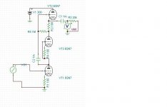
More Mu Follower.
Substitute the plate resistor of the lower tube with a constant current device. In this case, I used another 6SN7. You can use other devices as long as they can handle 100 volts or so.
THD is 0.003% @ 1.3Vrms out into 10kohms @ 1kHz.
DC current is 8.62mA. Well within max. plate dissipation.
S/N is nearly 120dB @ 1kHz.
Gain is the same at 25dB or so.
Really great performance.
Happy trails.
Attachments
Last edited:
- Home
- Source & Line
- Analogue Source
- Valve Itch phono