Stefanoo:
I don't know how much noise a motor with brushes will contribute to the overall noise figure. Maxon has brushless motors also, but I do not know if it will be better for our particular needs or not. I think you are on the right track. Thanks for your efforts.
I don't know how much noise a motor with brushes will contribute to the overall noise figure. Maxon has brushless motors also, but I do not know if it will be better for our particular needs or not. I think you are on the right track. Thanks for your efforts.
Arch Stanton:
You obviously know more than me about motors.
The good thing about Maxon is they sell motor controllers for their motors. Maybe there is a possible of an off the shelf solution to this great motor/controller caper.
You obviously know more than me about motors.
The good thing about Maxon is they sell motor controllers for their motors. Maybe there is a possible of an off the shelf solution to this great motor/controller caper.
You know, a brushless motor is an AC polyphase motor.
How would you say that a DC motor is an AC motor but polyphase? I am not sure that it is the case. Please explain further. One works with DC and the other one with dual phase AC (or 3 phase depending on the type of motor!)
However much, the DC motor due to its permanent magnet construction and technology, will be definitely prone to less vibration than the AC’s, I hope we all agree on this at least. 😀
The problem is that if we want to do a RIM drive implementation, then we need a CCW motor and it doesn't seem to be so easy to find with the features I am looking for.
I tried to call Maxon but they weren't available this morning I will try again a little later and then let you all know what my findings are.
If they wouldn't have CCW motors, would it be reasonable to think about an external solution with holographic mylar tape?
I would rather do RIM drive, but that is the closes one to direct drive and still requires a very low noise motor to do.
Any thoughts?
Brushless motor is not a DC motor. The DC supply is not connected to the motor.
It is a polyphase motor powered by an inverter and that inverter is powered by the DC supply.
The currents flowing from the inverter to the motor are AC.
It is a polyphase motor powered by an inverter and that inverter is powered by the DC supply.
The currents flowing from the inverter to the motor are AC.
The engineers at Maxon weren't available today, so I got the contact of one of them and emailed him our requirements and specifically the motor I picked and see if they have a CCW rotation configurable for that one and/or, if he has a better recommendation for low noise and high torque.
I will keep you guys posted on this. Tonight I will try to send a sketch of the mechanical design I have in mind.
I will keep you guys posted on this. Tonight I will try to send a sketch of the mechanical design I have in mind.
Brushless motor is not a DC motor. The DC supply is not connected to the motor.
It is a polyphase motor powered by an inverter and that inverter is powered by the DC supply.
The currents flowing from the inverter to the motor are AC.
oh really? Interesting I didn't know that.
Well, this specific motor I picked is precious metal brushes, therefore it should be a truly DC motor if I am not wrong!...please correct me if I am saying something incorrect.
Thanks for your input!
Mechanical Support
Hello all, I found this thread as I am searching for a quiet replacement to my Hurst motor. I have a VPI scout TT, and the noise between tracks is most annoying, I almost got up and looked outside for the source last night.
There was talk of multiple motors and a rim drive, I see the rim drive as an opportunity to mount a Tachometer or other feedback device underneath and out of site, as it would be a spindle supported by its own bearings, if I understand correctly.
Plus there was talk of three motors vs. one, well why not two?
Stefanoo, a DC motor will rotate opposite direction by changing polarity of the leads.
I can help with producing prototypes, I live near to the Wisco/IL boarder and we have several machine shops in the area, we produce aerospace parts mostly out of Aluminum.
You are hired, your resume is an overkill for the position 🙂
Sorry for my late answer, I was supposed to sketch something for here for everybody, but I didn't have a second today ad I was busy with prototypes of one of new designs.
I will try to get it done tomorrow morning.
I got an answer from maxon, I will share it tomorrow as it might be of interest to everybody.
The 2 or 3 motor solution has been my initial idea, but not everyone was on board. I like to say there is a lot of development before perfecting it and that was one of the reason why it was dropped.
Like someone else pointed out here, it's hard to not have only one motor being the generator which defeats the purpose.
Yes, leads on a DC motor can be swapped to reverse direction, but I was reading around, that torque and noise might not be the same on reversed polarity which I wouldn't understand why and how could that be and it is questionable.
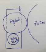
We could still do the if everybody likes it, if you are able to produce precise bearing (you and Jamie can split the workload, whatever you guys prefer, or maybe establish who has better equipment and knowledge), one powerful and quiet motor with flywheel that goes in touch with the platter. Everything in direct contact. This to me still has one advantage over direct rim which is dampening any residual vibration and provide more speed stability due to added flywheel.
Please anybody comment on this so I can eventually start sketching out the idea we would all like to move forward with.
12.30AM here...time for me to hit the sack....

😎
i think in true diyaudio style you should make boards available with a BOM so people can build themselves.
people could tailor the build for rim or belt drive as all it would take is a change of pulley. if people want to get together and have pods etc.etc for specific TT's then that would also be great. PCB should be threw hole for parts and ease of build.
lets not go mental on the quality of motor so it's available to people of all walks of life. $100-150 for motor should get a decent DC motor.
i'm very interested in a DC replacement of AC motor.
Brushless motor is not a DC motor. The DC supply is not connected to the motor.
It is a polyphase motor powered by an inverter and that inverter is powered by the DC supply.
The currents flowing from the inverter to the motor are AC.
You are correct that the DC current is not directly applied to the motor, but it might be a bit of a misnomer to say they are not DC motors. In a brushed DC motor, the polarity of the current is switched (alternated) through the winding in the rotor (the magnets are stationary) by the brushes and commutator. The speed of a brushed DC motor is determined by the voltage (therefore current) through the windings and commutation occurs automatically as the coils rotate.
In a brushless DC motor, the coils are stationary and the magnets are rotating on the shaft. The speed is still primarily a function of voltage and current in the coils which now has to be commutated electrically by the controller. Feedback (usually from hall effect sensors) signal the controller when (how frequently) to commutate the current in the coils. It might appear that the frequency of the controller determines the speed, but the motor instructs the controller how fast to commutate and the speed of rotation is still dictated by the DC current flowing (sometimes in alternating directions) in the coils. The most common type of controller uses block commutation where only 2 of the 3 coils are conducting at any given time, the 3 windings connected to a 3 phase bridge output stage with 6 phases per cycle. This arrangement still produces torque ripple (cogging), but is the simplest method of driving a BLDC motor.
To reduce or eliminate cogging, all three windings can be driven (commutated) with a 3 phase AC sinewave controller rather than the simple inverter. This requires much more accurate position information than the hall sensors, so is usually done with a high resolution encoder input in conjunction with the hall sensors. The algorithm to properly commutate with 3 phase AC is math intensive and usually done with a DSP implementation. Further improvements can be achieved by use of a Field Oriented Control (FOC) algorithm which senses current in the coils to interpolate the magnetizing and torque (D & Q) components occurring within the motor to develop the driving waveforms. This would be the best way to drive a BLDC motor for a TT application as it produces the least amount of cogging. However, I think this type of controller would not be suited as a DIY project.
To reverse the motor you can use it upside down.
I thought of that too ahaha...but then it would pose a problem how you assemble everything with a pulley that displaces off from the enclosure, I mean really not practical 😱
i think in true diyaudio style you should make boards available with a BOM so people can build themselves.
people could tailor the build for rim or belt drive as all it would take is a change of pulley. if people want to get together and have pods etc.etc for specific TT's then that would also be great. PCB should be threw hole for parts and ease of build.
lets not go mental on the quality of motor so it's available to people of all walks of life. $100-150 for motor should get a decent DC motor.
i'm very interested in a DC replacement of AC motor.
Agreed. I think in the name of flexibility the controller should at least have the ability to use current sensing for torque compensation. The PCB could be laid out with these components, but the individual users could decide whether they want to implement that control scheme (populate those components) or not. Whoever designs the controller should provide a decent theory of operation and formulas for component selection in case someone wants to modify the controller for a different implementation or to "hot rod" it.
i think in true diyaudio style you should make boards available with a BOM so people can build themselves.
people could tailor the build for rim or belt drive as all it would take is a change of pulley. if people want to get together and have pods etc.etc for specific TT's then that would also be great. PCB should be threw hole for parts and ease of build.
lets not go mental on the quality of motor so it's available to people of all walks of life. $100-150 for motor should get a decent DC motor.
i'm very interested in a DC replacement of AC motor.
Hi biblio!
This project is not intended to make a medium quality design.
My intention here is to set a new standard for speed regulation and noise.
Motor elected will be the best available and users can feel free to replace it if they want based on specs.
The controller can be all TH parts, no problem with BOM and Gerbers available.
Either way though, you will need to program a uC and the uC might not be TH but rather SM, to be defined.
This project will be tailored for RIM drive and I am afraid it won't be easy to adapt it to belt by simply changing pulley, because the speed of the rotation will have to change significantly.
Controller can be made available, no problem so the user can do even more DIY and tailor perhaps a different motor and speed, play around, but the official release will be for RIM drive and high quality DC motor.
Hope this sounds like a plan.
Agreed. I think in the name of flexibility the controller should at least have the ability to use current sensing for torque compensation. The PCB could be laid out with these components, but the individual users could decide whether they want to implement that control scheme (populate those components) or not. Whoever designs the controller should provide a decent theory of operation and formulas for component selection in case someone wants to modify the controller for a different implementation or to "hot rod" it.
Yes, we can have current feedback if ever, but I don’t think it is necessary. I want to see how many people would like to see torque compensation.
In all my readings I have done so far, the torque compensation is not good for sound at all and it can’t just be laid out and then not populated, I feel that having the current feedback is all a design topology change, but I might be wrong.
The best solution is to have a top level supply controller with very low impedance and extremely thermal stable output voltage with uC interacting in feedback with the tachometer to adjust the voltage.
Pairing this up with a top level motor and you got a top level DC motor system drive, I feel we should strive for this.
The flexibility on the controller IMO comes from the possibility to adjust whatever speed you want and have a wide range of output voltage available.
Since nobody will use this controller with a motor and then put gears to slow it down, the motor will have to be driven at low voltage, so perhaps if the controller can boost 2-10V this will be a wide enough range that will allow the user to use different pulleys combination with the same controller.
So, if users don’t want to use the same motor and get a cheaper one, they can still use the controller get a different motor with a different speed, make their own pulley and pad and adjust the controller for proper speed (actually the controller will automatically adjust it for it).
However the final release will be for a specific motor with specific pod and pulley and controller will be the same and it will probably be a package deal. People can then purchase assembled and tested controller or make their own since BOM and schematic will be released by me at the end of the project.
Polarities can be swapped and system converted to belt drive as well as RIM drive.
Is the any comment on this or everybody is happy with this?
Let’s just establish the team members for this projects so that it will be easier to direct the proper question (HW, SW or mechanical related) and everything can be crystal clear and we can move foward
Stefano HW designer
Pyramid SW designer
Jamie/ bfg4wd Mechanical designer
Please confirm if above statement is correct!
I am going to draft a concept design and see if everybody likes it or not.
I'm still on board to do the firmware.
I'm not saying one design approach is better than another. However from many years of designing products commercially, it is better to have a lot of discussion in the early planning stages to determine the design parameters before spending a lot of time and money on prototypes, only to have to make major changes later. This is true in hardware as well as software. While I want to see this project thru to completion in a relatively short time, I also don't want to rush to decisions, especially when others are involved in the process.
Regarding current compensation, it could be done in the µP and implemented as an option with a solder jumper, or it could be done as analog, adding the compensation voltage to the ref and defeated (or adding) it via a jumper.
Regarding voltage range for the motor, it will have a direct impact on the choice of DAC and the resolution of the voltage reference. The original design I sent to you was based on a 12 bit DAC and an output range of 0-4.096V with 1mV resolution. Using the same DAC with a 0-10.24V range reduces the resolution to 2.5mV (which may still be sufficient).
DC motors can still exhibit cogging if they have iron cores and there is bearing and brush noise that needs to be evaluated as well. Would it be wise to demo several motors to determine which one (or range of motors based on performance, price etc.) is best suited?
The best solution is to have a top level supply controller with very low impedance and extremely thermal stable output voltage with uC interacting in feedback with the tachometer to adjust the voltage.
I'm not advocating using current compensation or not. I just think it might be wise to include that option. FYI, no matter how accurate the regulator or how low of output impedance, the DC motor will exhibit speed change with a change in torque, even with constant voltage and zero impedance. The change in torque can come from the difference in needle drag at the outer edge disc vs the smaller diameter inner circle and from heating in the motor over time. Whether to compensate for this or not is a debate in the audio community and like all debates, has it's proponents and opponents.
The best solution is to have a top level supply controller with very low impedance and extremely thermal stable output voltage with uC interacting in feedback with the tachometer to adjust the voltage.
Pairing this up with a top level motor and you got a top level DC motor system drive, I feel we should strive for this.
Likewise, I think the tach input is an option, some may decide to not implement this for a number of reasons.
- Status
- Not open for further replies.
- Home
- Source & Line
- Analogue Source
- Hurst AC Motor Let's upgrade it