.
Can anybody tell me why I'm frying NE5532s? Have I just got a wrong idea, is this setup not possible?
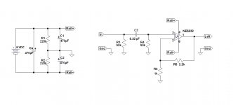
As you probably see, this is Chu Moy's voltage divider power supply from his famous Cmoy headphone amp. He uses an OPA134 or OPA2134, here the same setup is applied to an NE5532.
But when power is applied the current draw is extreme. Battery voltage drops and the NE5532 gets very hot. I didn't know you could melt a breadboard, you'd think they'd make them out of hi-temp plastic. Or maybe they do.
Am I not seeing something? Is this setup just not possible with an NE5532? Something...what?
PS the filter capacitors are ridiculously huge because I actually intended to use a wall wart power supply, not a battery. The battery is just for testing...and cooking ICs.
.
Can anybody tell me why I'm frying NE5532s? Have I just got a wrong idea, is this setup not possible?
As you probably see, this is Chu Moy's voltage divider power supply from his famous Cmoy headphone amp. He uses an OPA134 or OPA2134, here the same setup is applied to an NE5532.
But when power is applied the current draw is extreme. Battery voltage drops and the NE5532 gets very hot. I didn't know you could melt a breadboard, you'd think they'd make them out of hi-temp plastic. Or maybe they do.
Am I not seeing something? Is this setup just not possible with an NE5532? Something...what?
PS the filter capacitors are ridiculously huge because I actually intended to use a wall wart power supply, not a battery. The battery is just for testing...and cooking ICs.
.
Attachments
Last edited:
You need to add another 9V battery,so that you will have plus and minus rails with a junction between the batteries supplying a centre tap to ground and consequently an earthed reference point.
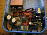
Hmm, i made a circuit very similar for a CMoy amp, single 9v battery feeding a 4556. The one thing i dont like in that schematic is the 470uf cap accross the battery...
Thanks for your reply, mcandmar. I'm not wed to Ca, I'll take it out in a second. But it doesn't seem at first thought that it would be a problem. With or without Ca it's still the same 9 volts DC applied to the same rails...at first thought.
I'm very interested to learn that the same setup worked with your NJM4556. So why not with an NE5532? I'm starting to think that the circuit is OK, it's me that's missing something.
EDIT:
On the other hand, there is a total of over 1,300uF filtering. So of course battery voltage will drop while those capacitors charge. I wonder what the insufficient power supply voltage might do to the NE5532? As you say, hmmm.
Last edited:
I'm not really sure why either, it just doesn't look right. I wish i had written the circuit down but looking at it here i can see the two divider resistors and caps to the left of the opamp. Defo works without emitting the magic smoke.
P.S. Just spotted something, in your schematic pin 4 and 8 are the wrong way around, 8 is + and 4 is -
P.S. Just spotted something, in your schematic pin 4 and 8 are the wrong way around, 8 is + and 4 is -
Attachments
Last edited:
Yes, that will explain your symptoms. You're probably in the market for a new NE5532.. . . P.S. Just spotted something, in your schematic pin 4 and 8 are the wrong way around, 8 is + and 4 is -
Dale
Slapping forehead, going dah. And I carefully checked my schematic against the data sheet, too. More than once. But I still somehow got things backward in my head, and once that happens, well, that's all she wrote.
Sadly, being melted several times seems to have affected my only breadboard in some negative way, so I can't immediately try this new technique of hooking things up right for a change. But when eBay sends me a new breadboard I'll report back with real-world results.
Meanwhile, I'm posting a corrected schematic to keep things clear for people who Google in 5 years from now. And thanks, mcandmar, for jumping in!
PS that's a very nice looking circuit you posted. I'm guessing it's related to NwAvGuy's O2 amp?
Attachments

Also reduce your splitting resistors, their impedance needs to be lower than what you are hanging off them. The caps will help at AC, but I'd be looking to use less than 10k.
PS that's a very nice looking circuit you posted. I'm guessing it's related to NwAvGuy's O2 amp?
Funny you should mention it i built that shortly after the O2 so you might spot the battery connectors and charging resistor that were left over from that build. The rest was bodged together from bits of CMoy, RA1, and various other schematics. The AC charging circuit was my own improvisation.
Funny you should mention it i built that shortly after the O2 so you might spot the battery connectors and charging resistor that were left over from that build. The rest was bodged together from bits of CMoy, RA1, and various other schematics. The AC charging circuit was my own improvisation.
Then just since the subject came up, you might be interested in Stephen Lafferty's Headbanger headphone amp, if you're not already familiar with it.
He uses the LM386, which has a bad rep among armchair experts, but Mr. Lafferty cut the gain, moved the feedback, and generally reworked things. The result is first class sound in my opinion.
The Headbanger's main strong points, aside from sounding good, are: 1. It drives any headphones known to man, and: 2. It's equally useful as a line driver. You can put your sound wo/man in the next county and s/he can still control your main amps on stage. (so important to be PC these days)
On the downside, it's best to follow Mr. Lafferty's layout, and his somewhat mysterious grounding instructions, or the thing will never work. Anyway it's at:
HeadBanger Headphone Amp Construction Kit
Of if diyaudio won't let me post a link it comes right up in a search for:
headbanger lafferty
But on to the business at hand.
...in your schematic pin 4 and 8 are the wrong way around, 8 is + and 4 is -...
On to present business. I found an un-melted spot on my breadboard, so I was able to assemble the circuit with the power connections corrected.
Yep mcandmar, you called it. Merely a matter of power being hooked up backward. Just two little wires, funny how the small things matter. Well, it was an easy mistake to make because the wires look almost the same. The only difference is that one is red and one is black.
In a sidebar, moving to an undamaged part of the breadboard also fixed a 120 Hz hum that I'd been looking for. This reinforces my conviction that 90.9% of so-called ground loops are due to bad connections. The math is: bad connection = resistance = voltage drop = noise.
So thanks again, mcandmar, for jumping in. I'd been looking for my problem for days so you saved my bacon.
And more thanks to richie00boy for pointing out my oversize splitting resistors. I don't know where I got their original values, but a power supply is supposed to be low impedance, right. I'd neglected that entirely.
I don't know why they make this stuff so complicated.
Last edited:
At my first "real" job - in an FM 2-way radio repair shop, after school and saturdays during High School - the shop owner was always telling the techs to "Mech FIRST!". Meaning, do a thorough visual inspection of the mechanical details of anything coming in for repair. Look for loose or missing tubes and components, unmated connectors, damaged wires, anything mechanically broken or discolored, etc. - and do this BEFORE turning on any test equipment or plugging in the soldering iron. Mechanical clues almost always pointed to the cause of an electronic problem, and were usually more time-efficient than doing electrical tests and troubleshooting.. . . Merely a matter of power being hooked up backward. Just two little wires, funny how the small things matter. . . .
In that repair shop we had the advantage of knowing that anything brought in for repair had been working at one time. When building a new piece of equipment you can't make that assumption. However, unless it's built from a completely new and unproven design, you can still assume that one like it has worked on somebody's bench - so "Mech FIRST!" still applies. You have to expand your checklist to include at least the most common assembly errors - wiring errors, solder bridges, cold solder joints, components incorrectly inserted, etc. The disadvantage is it usually takes a new set of eyes to do this inspection effectively but often just setting the project aside for half a day, or even long enough to have lunch, will give you enough of a fresh perspective to find your mistakes.
Dale
.
Wise counsel. And don't forget the three most important questions of all to ask every customer.
1. Is it plugged in?
2. Is it turned on?
3. Are you absolutely sure it's plugged in and turned on? Would you look again, please?
3a. And in the case of computers: have you tried restarting?
Thanks again for your help!
.
Last edited:
Here is an idea...
Keep the splitting resistor at 220K if you want but use 1% or better, bypass the mid point with 2 X 100uF or so electrolytic between each leg of the supply, watch for the polarity!
Connect this point to the + input of an op-amp, you don't need anything fancy, it will work just fine with anything. Connect the output of the op-amp to the - input.
Now the mid point is buffered and will have a very low impedance and the output will track nicely at mid point as the battery discharge. The reason for this is to lower the Z of your ''ground'' which will have essentialy the output Z of the op-amp, not the 220K.
Luc
I believe that circuit is sometimes called a "rail splitter". The opamp's output terminal may be called an "artificial ground" or "virtual ground". It costs you the price of the opamp, plus the PWB acreage to put it on, and the few mA of supply current the opamp draws from the battery. There are a few examples floating around the 'net. I think TI (and possibly others) offer a product with the opamp plus precision resistors all connected in a single package with just 3 or 4 pins.Here is an idea...
Dale
Not to get too far off this track, but since it's been mentioned already...
Though I've never tried it, I've sometimes wondered if a little chip amp like the LM386 could be used as a rail splitter. The output gets biased at approximately half supply; it seems to me not totally unlike some of the op amp splitter circuits and chips. Any thoughts? Am I overlooking the obvious? I'm prepared to be shot down...
Though I've never tried it, I've sometimes wondered if a little chip amp like the LM386 could be used as a rail splitter. The output gets biased at approximately half supply; it seems to me not totally unlike some of the op amp splitter circuits and chips. Any thoughts? Am I overlooking the obvious? I'm prepared to be shot down...
The input bias currents of the FET input OPA2134's will not be enough to affect the mid rail point when using those high 220k resistors. But the NE5532 is bipolar, not FET, and it has orders of magnitude more input bias current. These may (read: will) affect the virtual ground voltage unless you decrease those resistors to provide a lower impedance path for that current.
- Status
- Not open for further replies.
- Home
- Amplifiers
- Power Supplies
- Why does this power supply not work?