I am planning to get a TPA3116 board from ( http://www.yuan-jing.com/tpa3116-class-d-stereo-amplifier-board-50w-50whttp://rover.ebay.com/rover/1/711-5...io01-20&ipn=psmain&kwid=902099&mtid=824&kw=lg )
I am planning to use them with my Fostex FF125WK. I am thinking about ways to make them run perhaps at a lower THD+N rating than they would at 50Watts. FF125WK is happy(and me) at even 15 watts for sure.
Is there anyway to modify this board or powersupply to make it run at a lower power rating and THD ?
Last edited:
Why is lower THD interesting to you - because you think it'll sound better? Or because you want to impress your mates with the numbers?
BTW the eBay link doesn't work.
BTW the eBay link doesn't work.
I do not know how much difference it will make.But seems lower THD +N is a desirable charecteristic for any amp ,but not the only one.
I do not need 50 Watts since FF125WK is rated 30watts nominal and if I can bring the THD down at least in theory I know this is the best the amp can sound like.
I just changed the link to another seller. Ebay links does not seems to work from this forum.
I do not need 50 Watts since FF125WK is rated 30watts nominal and if I can bring the THD down at least in theory I know this is the best the amp can sound like.
I just changed the link to another seller. Ebay links does not seems to work from this forum.
I reckon that sound quality in an amp is more related to the power supply quality, not the THD. Plenty of amps with relatively high THD (low order harmonics) sound decent. So I'd not focus on THD, rather on PSRR and getting the lowest noise on your supply. Digital amps that I've seen don't have nearly enough capacitance on the supply to get the noise down.
As you need fewer watts, you can reduce the supply voltage in the first instance. In the second, fit plenty of 10uF 25V 1206 ceramics across the supply. By plenty I mean dozens of them.
As regards the amps on eBay, I'd only recommend the ones with toroidal (iron powder-based) output inductors. The one you've linked uses fairly puny SMT (ferrite) chokes.
Why is lower THD interesting to you - because you think it'll sound better? Or because you want to impress your mates with the numbers?
This is a very rude way to initiate a conversation. He has no right to ascribe what he obviously considers baser motivations to you. Don't let this guy intimidate you, his opinions about THD and PSRR are far from widely held, he's just looking for somebody that he feels free to bully, he certainly doesn't deserve any thanks.
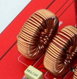
eBay has them - after your first link failed I just typed 'TPA3116' into its search function and it showed boards using toroidal output inductors - they're a bit more expensive than those with the ferrite chokes, but a difference well worth paying in my estimation. Do you know how to recognize the better output chokes? If not I'll post up an image to help.
You're right - the boards with the decent chokes are all 2.1. Is that a big problem for you? All other things being equal they should have more supply capacitance so ought to sound better if the .1 output isn't used.
This is what a toroidal output choke looks like :
This is what a toroidal output choke looks like :
Attachments
This is a very rude way to initiate a conversation. He has no right to ascribe what he obviously considers baser motivations to you.
This is hilarious - I asked a question and questions don't attribute motives, base or otherwise. 'Obvious' is it? - then you'll be able to point to what you saw, Do please do so.
More hilarity 😀 Whilst I agree my experience isn't widely shared, its experience rather than opinion as you're claiming here. I do also agree that there's no need to be intimidated, since none is intended by me.Don't let this guy intimidate you, his opinions about THD and PSRR are far from widely held, he's just looking for somebody that he feels free to bully, he certainly doesn't deserve any thanks.
Last edited:
All opinions are appreciated. Please do not argue here. I too agree that THD +N is not everything. I am still waiting to hear from someone who can share how to lower the power out from the board.Is it by lowering supply voltage ? Lower power out from board means lower THD ?
When I looked at the DS for another chip in TI's family of PWM amp chips, I noticed that the PSRR at maximum voltage is up to 10dB worse than at lower voltages. So I reckon your idea of only running the chip at the actual power rating you want makes a lot of sense. The DS for the TPA3116 doesn't include PSRR comparisons at different operating supply voltages but I see no reason to believe the amp circuitry is significantly different between the various parts in their family.
Running a lower supply voltage also allows you to fit more uF onto the board as lower voltage caps take up a little less room. Suggest you try running just below 16V, allowing 16V electrolytics to be used on the supply.
Running a lower supply voltage also allows you to fit more uF onto the board as lower voltage caps take up a little less room. Suggest you try running just below 16V, allowing 16V electrolytics to be used on the supply.
How much power output is expected at 16Volt? Is there any way to calculate the voltage in vs power output ?
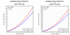
The output power rating depends on how much distortion you decide to accept (1% and 10% are common choices) and the load impedance. In the DS the 10% THD point into 4R is 25W typically, at 14.4V. Going to 16V would give you about 30W. If you choose the more conservative 1% distortion point, you'll get a lower power.
Here are two graphs from the DS - left is 8ohms, right 4ohms. The red line is for 10% THD.
Here are two graphs from the DS - left is 8ohms, right 4ohms. The red line is for 10% THD.
Attachments
What are the requirement or changes in circuit for making THD 1%? how can it be 10% and 1% at same voltage?
Last edited:
The choice of 1% or 10% is up to the person doing the measurement. If someone wants higher numbers, they'll go for the 10% figure. Myself I tend to prefer even less than 1% - onset of clipping is where I measure output power, but that's rather subjectively determined on a scope as I don't have a THD analyser.
Its not '10% and 1% at the same voltage' rather the 10% figure represents a more 'square' sinewave signal and hence higher power than for 1%. Another way of looking at it is the 10% figure is taken with the volume control set higher (more gain).
Its not '10% and 1% at the same voltage' rather the 10% figure represents a more 'square' sinewave signal and hence higher power than for 1%. Another way of looking at it is the 10% figure is taken with the volume control set higher (more gain).
I do not know about the filter part on those 2.1 boards. Since it comes with its own volume control, I am bit suspecious about 2.1 board. Do not you think it will have an effect on stereo channels even if Do not use the subwoofer channel?
The TPA3116D2 is rated for 50 WPC into 4 ohm loads. It will provide about 30 WPC with 8 ohm speakers. The chip has power limit features, but most boards do not implement them.
Just about any amp will do this. The distortion is quite low, below 0.1% at low power levels for most audio frequencies. As you drive the amp harder (turn it up louder) the distortion gently rises until the point of clipping is approached, then rises rather rapidly. The power output is measured at the point the distortion reaches 1%. The volume is then increased until the distortion reads 10% and the output power is measured again.
You can lower the output power by reducing the supply voltage. I have one of the 2.1 boards and I tested it on a high quality lab type variable power supply. It just seems to sound better at 24 volts even at low volume levels. I am also using 8 ohm speakers.
These class D chips have a design characteristic that causes a peak in THD at about 6KHz. This can not be easily changed from outside the chip, if at all.
I have the 2.1 board with the toroidal chokes. I am not using the subwoofer channel at this time since my system already has a powered sub. I put a 10 ohm resistor across the speaker terminals (just in case) and turned the "bass volume" all the way down. I am running it on a 24 volt SMPS. This board has two 10,000 uF capacitors across the power supply lines.
What are the requirement or changes in circuit for making THD %? how can it be 10% and 1% at same voltage?
Just about any amp will do this. The distortion is quite low, below 0.1% at low power levels for most audio frequencies. As you drive the amp harder (turn it up louder) the distortion gently rises until the point of clipping is approached, then rises rather rapidly. The power output is measured at the point the distortion reaches 1%. The volume is then increased until the distortion reads 10% and the output power is measured again.
You can lower the output power by reducing the supply voltage. I have one of the 2.1 boards and I tested it on a high quality lab type variable power supply. It just seems to sound better at 24 volts even at low volume levels. I am also using 8 ohm speakers.
These class D chips have a design characteristic that causes a peak in THD at about 6KHz. This can not be easily changed from outside the chip, if at all.
All other things being equal they should have more supply capacitance so ought to sound better if the .1 output isn't used.
I have the 2.1 board with the toroidal chokes. I am not using the subwoofer channel at this time since my system already has a powered sub. I put a 10 ohm resistor across the speaker terminals (just in case) and turned the "bass volume" all the way down. I am running it on a 24 volt SMPS. This board has two 10,000 uF capacitors across the power supply lines.
I'd just connect an 8R resistor across the sub output but set the volume down to zero. In this way the amp's loading is the same but it won't take any extra power from the supply - the output filter normally needs the load impedance connected to ensure it operates correctly.
😀 I see independently tubelab has said almost the same thing.
😀 I see independently tubelab has said almost the same thing.
- Status
- Not open for further replies.
- Home
- Amplifiers
- Class D
- TPA3116D2 lowest THD+N