Circuit may oscillate because it inverts the phase of the input signal. It is unlike the negative feedback in F5.If we connect bottom of R3 to top of R7 in your schematic, are we looking at current feedback? Also, I was not able to see Nelson's implemetation, but it looked like the Vref section for the folded portion was tied to the output. Would this effect performance?
Playing with the bias resistors and the output resistor of the circuit in post #57 cut the gain down to 6X, and the THD is down almost by a factor of 10, mostly by optimizing the bias current in the cascode jfets. Not shabby for dirt-cheap devices. I may play with biasing the preamp with a pair of current sources (easily implemented with depletion mode mosfets) in order to lessen the dependence on the power supply rails.
Was the optimized "bias current in the cascode JFETs" = to the input JFETs current or?Playing with the bias resistors and the output resistor of the circuit in post #57 cut the gain down to 6X, and the THD is down almost by a factor of 10, mostly by optimizing the bias current in the cascode jfets. Not shabby for dirt-cheap devices. I may play with biasing the preamp with a pair of current sources (easily implemented with depletion mode mosfets) in order to lessen the dependence on the power supply rails.
Also, you did not use a center point of GND for your cascode refrence Voltage string as N.P. and Juma did. Any pros or cons to that?
Super Symmetry
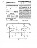
Keeps coming around. The circuits presented by Mr. Pass at BAF13 and yours are amenable to Super Symmetry operation. Thus one gets a simultaneous balanced operation and a reduction in distortion. The attached picture explains this well-known implementation by Mr. Pass. Two ~identical circuits [like yours and Mr. Pass] are bridged by resistors #40, 42 and 43.
Best regards
Playing with the bias resistors and the output resistor of the circuit in post #57 cut the gain down to 6X, and the THD is down almost by a factor of 10, mostly by optimizing the bias current in the cascode jfets. Not shabby for dirt-cheap devices. I may play with biasing the preamp with a pair of current sources (easily implemented with depletion mode mosfets) in order to lessen the dependence on the power supply rails.
Keeps coming around. The circuits presented by Mr. Pass at BAF13 and yours are amenable to Super Symmetry operation. Thus one gets a simultaneous balanced operation and a reduction in distortion. The attached picture explains this well-known implementation by Mr. Pass. Two ~identical circuits [like yours and Mr. Pass] are bridged by resistors #40, 42 and 43.
Best regards
Attachments
I added a ZVN/ZVP Zetex/Diodes Inc. mosfet output buffer to the basic circuit, biased by a quad of GaAsP ancient LEDS, and the distortion goes down, as well as beefing up the output drive. I may start a thread on an RIAA/line pre based on this topology, not that I'll be building it in the near future...
What appealed to me about this circuit is it's elegance, scalability (wide range of gain and output level settings, all without feedback loop), wide usability range and, most importantly, extraordinary good sound (I'd describe it as perfectly clear and detailed, strongly vivid, neutral and transparent but emotional and pleasant in presentation) so I've been playing with different versions of this preamp for the last two weeks and I think now I can share my impressions. I toyed mostly with:
- CCS instead of resistor to supply the current into cascoding node
- different input devices (j74/k170 V and BL grade, k246/j103 GR and BL grade),
- different PS and cascode voltages,
- different gain levels and different gain distribution between input and cascode,
- different currents through cascode (for the input I always chose most linear region close to Idss),
- different cascode devices (j74/k170, j103/k246, j313/k2013, BC550c/BC560c).
Since I need a high gain and high output (for low level sources and for driving a small/medium power followers), I opted for gain of 19dB (9V/V) and for about 12V_RMS of output.
The schematics shows the circuit I like the most - j74V/k170V (I managed to obtain 2 pairs) as input devices and BJTs as cascodes, followed by a very nice SE, cascoded, BF862 buffer stage that can happily swing more than 20V_peak into 10k load. Buffer enables a use of low gm JFETs at input which leads to high Zout (k246/j103 sounded really great too, I think I chose j74/k170 over them only because it would be a shame to left them unused after all the trouble I went through to obtain them).
Thermal drift is small - few mV in the preamp (which can be improved by thermal coupling of transistors) and less than 1mV in the buffer, but instead I added a nice small coupling cap between them (WIMA MKP10, 100nF) just to make sure that naughty source component won't make a mess.
R14 and C3 snubber I put for hygiene reasons - a lot of experimenting went on here and I wanted to limit a preamp's band a bit - with a snubber it's good up to almost 200kHz.
PSU is self-explanatory - good thing here is that circuit has a constant current draw so the three legged regs can be used with RC filter after them which solves their greatest problem, the HF noise.
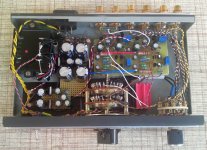
I had the suitable case handy (with connectors, selector and attenuator already done) so I used it although it's very small (22x5x13 cm). That's why it looks messy - the wiring scheme had to compensate for the lack of space.
This post starts to look like blog so I'll stop now - feel free to ask things I forgot to write about...
- CCS instead of resistor to supply the current into cascoding node
- different input devices (j74/k170 V and BL grade, k246/j103 GR and BL grade),
- different PS and cascode voltages,
- different gain levels and different gain distribution between input and cascode,
- different currents through cascode (for the input I always chose most linear region close to Idss),
- different cascode devices (j74/k170, j103/k246, j313/k2013, BC550c/BC560c).
Since I need a high gain and high output (for low level sources and for driving a small/medium power followers), I opted for gain of 19dB (9V/V) and for about 12V_RMS of output.
The schematics shows the circuit I like the most - j74V/k170V (I managed to obtain 2 pairs) as input devices and BJTs as cascodes, followed by a very nice SE, cascoded, BF862 buffer stage that can happily swing more than 20V_peak into 10k load. Buffer enables a use of low gm JFETs at input which leads to high Zout (k246/j103 sounded really great too, I think I chose j74/k170 over them only because it would be a shame to left them unused after all the trouble I went through to obtain them).
Thermal drift is small - few mV in the preamp (which can be improved by thermal coupling of transistors) and less than 1mV in the buffer, but instead I added a nice small coupling cap between them (WIMA MKP10, 100nF) just to make sure that naughty source component won't make a mess.
R14 and C3 snubber I put for hygiene reasons - a lot of experimenting went on here and I wanted to limit a preamp's band a bit - with a snubber it's good up to almost 200kHz.
PSU is self-explanatory - good thing here is that circuit has a constant current draw so the three legged regs can be used with RC filter after them which solves their greatest problem, the HF noise.
I had the suitable case handy (with connectors, selector and attenuator already done) so I used it although it's very small (22x5x13 cm). That's why it looks messy - the wiring scheme had to compensate for the lack of space.
This post starts to look like blog so I'll stop now - feel free to ask things I forgot to write about...
Attachments


I've been doing some similar futzing about, but with the cheap vintage fets. The circuit shown has a gain of ~6V/V.
I used current sources (depletion mode mosfets in real practice) to set the currents in the gain and cascode devices, granting some supply voltage/ripple immunity. The output is a simple complementary common emitter darlington stage biased by a pair of GaAsP LEDS, represented in the simulation by voltage sources and series resistors. In practice, the voltage across the LEDs would be somewhat lower than in the simulation, as they are run at relatively low current.
I started this exercise with mosfet common source outputs, but ended with small signal darlingtons, as they are closer complements for biasing purposes than the mosfets, and didn't appear to make a whole lot of difference in the simulated THD. I'll be using MPSW45 and MPSW63, as I have bunches handy. Zetex/Diodes, Inc. has a suitable pair of devices (ZTX605 and 705). I opted for E-line or TO-92L devices to give me more options in output bias current, but you could also use readily available TO-92 devices such as the ones shown in the simulation, as long as you keep the output device dissipation below ~200mW or add supplemental heat sinks.
The results are not shabby at all for a small pinch (not even a handful) of cheap components. This same gain cell with some variations could be used to construct an RIAA preamp plus line stage. I would most likely use the cheap jfets for RIAA 2nd stage and line amp duty, but would consider using the superior Toshiba/Linear Systems devices for the RIAA input stage.
Attachments
Great work Yuma, I had the same impression about the circuit. I use a different but similar concept for a gain stage in my new power amp. With all respect I`m bit allergic on LM317 in a kind a SOTA circuit like this. I think a nfb shunts would improve things quite a bit.
Cheers, Borko!
Cheers, Borko!
You are welcome !That is wonderful!!!
Thank you!
If you look at the sch. you'll see that preamp is supplied by capacitance multipliers and 7{8,9}24 are used for the buffer - there is no LM317 in the circuit although I don't shun from using it when I can put the RC filter (with nice polymer elkos) after it to iron out the HF noise. As for the possible improvements I didn't find the circuit lacking in any way - IMHO there's nothing to improve....Great work Yuma, I had the same impression about the circuit. I use a different but similar concept for a gain stage in my new power amp. With all respect I`m bit allergic on LM317 in a kind a SOTA circuit like this. I think a nfb shunts would improve things quite a bit.
Cheers, Borko!
One more thing - I forgot to post the version with k246/j103. The buffer on the output is obligatory here.
Can K246/j103 GR used here ?
Didiet
Here is an extremely fast, low impedance shunt regulator that can be built with readily obtainable parts. The circuit looks kinda busy, but that's 'cause it's both plus and minus supplies. Expect to need at least 6V of headroom (I usually go for ~10V). The circuit is set for ~ +/- 24V output, settable via the voltages of the zener diodes. The output voltage is the zener voltage + 0.6V.
Attachments
Can K246/j103 GR used here ?
Didiet
Yes, especially form upper GR range (Idss of 5-6mA). For the lower Idss parts, some values should be recalculated.
LSK Preamp meets Buzquito?
Hi Juma,
Thanks a lot for the great bjt cascode version implementation of the PASS BAF2013 LSK preamp.
I came up with an idea and hope that you do not mind my using photoshop to merge several of your schematics of LSK Preamp, F5 meets Buzquito and addition of 2x150R at (R23 & R24) for an integrated with no global NFB. Any comments or suggestions for a build with sk/sj pair at idss about 10ma?
Thanks in advance.
Attachments
Yes, it works great - adding a source follower made of laterals at the LSKpre output.
Some changes are needed if you want to use k170/j74 with Idss of 10mA, but it all depends on:
1. how much power (on what load) do you want (to calculate the PSU dependent values)
2. what's the output level of your source component (to calculate the gain dependent values)
Some changes are needed if you want to use k170/j74 with Idss of 10mA, but it all depends on:
1. how much power (on what load) do you want (to calculate the PSU dependent values)
2. what's the output level of your source component (to calculate the gain dependent values)
Last edited:

Hi Juma,
For the circuit in post #66 what is total current draw ?...I'm wondering if i can get away with a 14 VA R-Core.
TKs
C
For the circuit in post #66 what is total current draw ?...I'm wondering if i can get away with a 14 VA R-Core.
TKs
C
Preamp draws 18ma per rail, per channel....For the circuit in post #66 what is total current draw ?...
Buffer draws 10mA per rail, per channel.
So,the total power consumption of the stereo preamp is about 3.5W
The transformer I use (you can see it in the pic, post #66) is a 10VA rated, so if you don't go crazy with PSU losses (an extra mad shunt reg for example) I'm sure you'll be fine with that R-core you got....I'm wondering if i can get away with a 14 VA R-Core.
P.S.
In next few hours we can expect a guy here, claiming that 50 or 100VA is a minimum requirement here, but don't pay any attention - I think he never held a transformer in his hands, let alone used one in a circuit... 😉
- Home
- Amplifiers
- Pass Labs
- LSK pre - BAF 2013