but the switching freq should be enough for subs right? 180khz is more than enough for <100HzThis amp isn't designed for hi-fi,but for PA is very good.For hi-fi frequency must be >300kHz.
any idea if they're stable when bridged? looking at the schematic posted they should work, but haven't got the time to actually test them yet.
On 180kHz i listen any music with no problems.High's are ok.
Yes,it's stable,only set zero V at both amp's.
It works,when you test,post here.
Yes,it's stable,only set zero V at both amp's.
It works,when you test,post here.
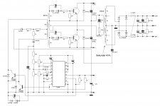
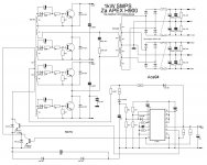
This smps can be used to power this amp.:
Uni SMPS 3 - Smps - DiyAudioProject
Need to register and log in to access the JPG files.🙁
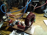
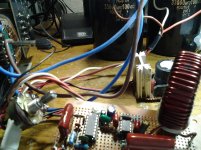
Yes steve,comparing to ucd the high's has a little cut off i think due to the SW. frequency on this circuit (as-is) it's around 150 khz as i measure on my counter at the output of SG after 1N4148,BUT ONE THING I NOTICE when i measured the frequency at the output terminal before the coil with refer to CENTER TAP it read's -/+300khz (maybe it can be corrected with F.B.)
With IRS900, let say our voltage will be -/+ 90VDC i can say this amp gives more power.
(This amp has higher efficiency than self osc. one)
With sir manojtm AUD600 it is a very good amp,i cannot compare because on AUD600 it uses a different approach ,try to build one steve and you can hear the difference & don't forget to share your PCB layout cause i don't have,more power to all DIYER'S.

And my amp have higher effidency than self osc.
Yes,highs have a small cut off,bit it's still good.
Can your counter withstand +-50V???
Measure f. at Gate-Source of lower fet,or at 4148 diodes at SG output (you measured there).
Yes,highs have a small cut off,bit it's still good.
Can your counter withstand +-50V???
Measure f. at Gate-Source of lower fet,or at 4148 diodes at SG output (you measured there).
Last edited:
There's few versions,self osc,classic with TL494 and 1kW with TL494.Need to register and log in to access the JPG files.🙁
Attachments

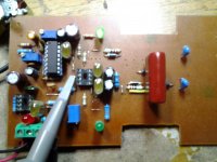
Thank's a lot Aleks,i'll try to fix a 1.5 uf and my inductor is 30uh hope the high's will not be more affected cause i'm going to use the amp for my full range application,hope to hear more from you Aleksandar,more support from you for all DIYER'S to build this project.
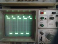
This is good waveform,but what is this peaks?
What is your supply voltage for IC's?
Try to remove power to fet's,only put 12V to IC's and see waveform.
And duty is not set at 50% (0V at uotput).Set it.
What is V/div. on picture?
Coupling AC or DC?
Real waveform should be square wave.
What is your supply voltage for IC's?
Try to remove power to fet's,only put 12V to IC's and see waveform.
And duty is not set at 50% (0V at uotput).Set it.
What is V/div. on picture?
Coupling AC or DC?
Real waveform should be square wave.
Last edited:
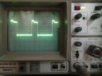
yes aleks the V/div. is .2V,AC coupled my probe was set to X10,voltage i'm using is 12V(LM7812) no voltage applied at the output section,i'm using KA3525A.
- Status
- Not open for further replies.
- Home
- Amplifiers
- Class D
- DIY Good Class D amplifier