rCRC is better than C.
Better in this case means more attenuation of the unwanted mains and it's harmonics and all the HF garbage that comes in with the mains.
If I use thick short cable that results in 2mill-ohms of flow and return total circuit resistance for one connection pair and instead I use a slightly longer twisted pair of thin guage and have maybe 15milli-ohms of circiut resistance than I have gained a free 13milli-ohms and I have gained again with low loop area.
Now repeat that before the rectifier, after the rectifier, before the amplifier. I could get an additional 30milli-ohms of "free" resistance to make up that r of the rCRC filtering.
Every time a little capacitance follows an r or R we have a filter. All those filters add up to massive attenuation of the HF arriving at the amplifier power rails.
BTW, I posted transformer test results showing secondary resistance of 90milli-ohms in the reservoir size Thread. an extra 30 is significant.
Roender's 300 is even more effective.
Last edited:
Why the use of double diodes in the bridge?
On the PCB design there is position for MUR120 diodes or MUR8x0 diodes. Use one or the other, depends on designed load current.
Well, If your shunt is designed for 3.3A then yes, the resistor should have 0.3ohm. The voltage dropped over this resistor should be around 1V
It's valid for all Salas shunt regulators?
Is valid for any shunt regulator, not only SALAS. Actually, is valid for any regulator who draw "constant" current, either series or shunt.
Thanks Salas, I use also RC but to down the voltage never measured to give 1V across the resistor.
That's a minimum ballpark drop for when the transformer does not give much to spare. Downing more voltage includes more filtering anyway. If there is no CCS it will modulate, only for CCS is all good. Even better is choke input IMHO.
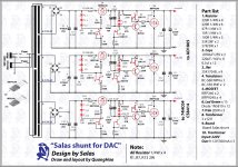
My attempt at a PCB for 5v Reflektor. Thanks for the help SALAS.
I should add that I inserted C1 as additional smoothing post rectification. If used, I'll obviously have to connect the + terminal.
Also, will be adding heatsinks for the mosfets.
Any comments?
I should add that I inserted C1 as additional smoothing post rectification. If used, I'll obviously have to connect the + terminal.
Also, will be adding heatsinks for the mosfets.
Any comments?
Attachments
Last edited:
Try to move R3 up and turn it to the left so to be horizontal and bang on gate so to work best as a gate stopper.
Since you are not planning a trimmer but a resistor (better for ppm and stability but fussy to set Vo), keep in mind that your Vo will be ((VgsM2/R6)*(Rtr))+LedVf(or diode)+2Vbe. CCT on #5376 post.
I assume you mean for the IRF9610 gate. Its the resistor I've labelled 150R2?
That on is near, talking the IRF940 one. You named it 150R3.
Quick question. I've built the shunt reg pictured in the first schematic in the picture below using one of dvb-projekts PCBs. C3 and C5 are listed as being 220uF. Would it be OK to use 330uF caps for those positions instead? I have a pair of 330uF/35v Rubycon ZLHs I found in the parts box here. If not suitable I'll order some 220uF types instead.
Thanks.
Thanks.
Attachments
- Status
- Not open for further replies.
- Home
- Amplifiers
- Power Supplies
- The simplistic Salas low voltage shunt regulator