Attachments
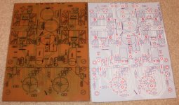
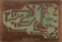
Iron on toner transfer etched in the sink............
They work great if you use the proper trace spacings for the voltage and watch for ground loops and positive feedback between traces.....
They work great if you use the proper trace spacings for the voltage and watch for ground loops and positive feedback between traces.....
Attachments
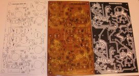
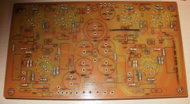
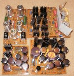
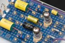
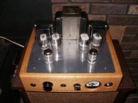
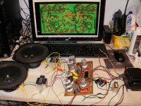
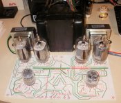
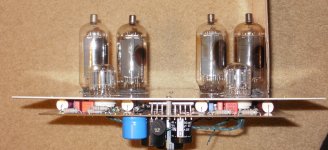
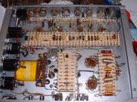
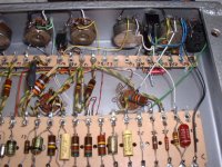
Thanks, the first PCB looked like #@%&#, it took me a few tries to get the iron hot enough for adequate toner transfer to the copper. A couples pic of the Amps process, the component placing and trace design, the etched PCB stuffed going through bias checks and feedback tweaking, and the little finished Amp. Where I connect with wires and mount caps on the bottom side, I use brass eyelets as feed-throughs. You don't have to worry about pulling the traces off of the PCB. The last pic is the last sweep tube amp in process. I stole the chassis to finish a 6L6-KT88 KEG-EAR Amp instead. Thanks another story.....
Attachments
I like to make my own PC boards. I found a pre-sensitized board that I can expose with a 100 watt light bulb. A 4X6 board cost about $5. I use windows paint to draw up the board, then print the foil pattern on a clear plastic sheet, expose the board and etch. From print to stuffing is about 30 minutes. Search this for one of my projects. (Want help - RCA Tube Manual RIAA Phono Stage ). I also made a PCB for the RH-84 SE amp, and I'm working on a 6BQ5 push pull. Google "Philmore-datak" for for info on the PC boards.
Attachments
Will certainly look at this, even though I use an LPKF rapid prototyping machine to knock out double sided PCBs.
IMHO, the MAJOR restriction in hobbyist electronics for me is the expense of getting PCBs made. I have however in the past 'added' some of my PCBs to gaps in PCBs that I have to get produced at work. Sneaky but effective!

Andy
Hi, bequerel,
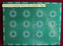
Where did you find prototyping board shown on the left (green).
I had limited success with toner transfer method until I tried the method described in this tutorial UltraKeet Australia. This method works almost flawlessly. The very important part is to use a toner transfer paper. It makes a HUGE difference using the right paper. You can get online with epay. Same goes for the toner reactive foils. Here is a link to modding a very inexpensive laminator UltraKeet Australia
This method is reasonably cheap, and very easy.
For producing the artwork, I now use Eagle Downloads | Get The Latest Version of EAGLE | CadSoft EAGLE |. There are various tutorials on how to use Eagle. Even if you do not etch your own boards, Eagle is great for creating a schematic and sending out for external board production.
Hope this helps.
Cheers,
Chris
It is possible to use something like this for PCB prototyping
Circuitworks MicroTip™ Conductive Silver Pen - PCB Repair - SPI Supplies
I was ordering similar silver pen from Newark
0000000000002200 - ITW CHEMTRONICS - CIRCUIT WORKS CONDUCTIVE PEN, | Newark
There is no any pro for PCB unless you can handle 3+ layers PCBs which is obviously out of scope for DIY so in case your project is simple enough for point-to point wiring it is the preferable way without doubts.
Usually UV lamp can be easily obtained at electronic hobbyist oriented stores where you will need to order chemicals for etching anyway.
There is no any pro for PCB unless you can handle 3+ layers PCBs which is obviously out of scope for DIY so in case your project is simple enough for point-to point wiring it is the preferable way without doubts.
If I understand you correctly, hardwiring is always advantageous if single layer? If I misunderstood, my apologies.
As pointed out in my white papers, the trick is to incorporate the advantage of boards with the advantages of hardwiring. As such PCBs actually offer several advantages.
1) Reduces number of wires and solder connections necessary by connecting leads to leads.
2) Spaces parts and "wires" off the chassis for much less stray capacitance.
3) Allows for better consistency between units being manufactured, such as high frequency and channel separation specs etc.
4) What foils are used can be quite wide for very low resistance.
There is virtually no advantage with hardwiring if pcbs are done correctly.
Cheers.
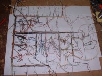
I prefer hardwiring, because:
Hi All,
it gives my equipment an old fashionend look as it fits to valve operated gear, it is easy to change the circuitry if my calculation doesn´t lead to the espected aim.
For some small pcbs such as power supplies I do it to Wavebourns method.
Professional made pcbs are quite expensive and it is not really a need of such.
Here an example of my Lowatt Guitar amp:
A two channel 10 Watt Combo.
See also my thread about my homebrew McIntosh MC-3500 clones.
73
Wolfgang
Attachments
PCB only, and definately only when I know that the circuit works, is proven and tested. I use Altium Designer, a very extensive and mighty software.
But mostly I use hardwiring. With 3 dimensions it is much more easy to get shorter tracks. No heat problems with power tubes and the most significant: Simple exchange of parts or circuit topology.
But mostly I use hardwiring. With 3 dimensions it is much more easy to get shorter tracks. No heat problems with power tubes and the most significant: Simple exchange of parts or circuit topology.
STEFKORN....
here is a link to the process I use to make PC boards.
The method is based upon using the Datak no
here is a link to the process I use to make PC boards.
The method is based upon using the Datak no
The amps the last the longest are not built on fiberglass boards.Hi guys,
Do you have any experience to share about the pros and cons of PCB vs hard wire. For my previous projects ( mainly head phone amps with valves ) is used
Tag boards only. Now I have a hybrid head phone amp in mind ( as on the Headwize site ) which really asks for a PCB. But tube bases on PCBs? Any suggestions?
Thanks in advance.
I have serviced amps for over 35 years, and time proves that the amps that withstand the test are built point to point, not on fiberglass.
PCB only, and definately only when I know that the circuit works, is proven and tested. I use Altium Designer, a very extensive and mighty software.
But mostly I use hardwiring. With 3 dimensions it is much more easy to get shorter tracks. No heat problems with power tubes and the most significant: Simple exchange of parts or circuit topology.
I agree, PCB is better, however Altium Designer costs in the order of $ 2 K.
I can live with that money four months !
ACCEL TangoPCB you can get it for free on the web.
It has no so many toys, but works pretty well.
TangoPCB is Altium Designer's grandfather.
Altium - Wikipedia, the free encyclopedia
- Status
- This old topic is closed. If you want to reopen this topic, contact a moderator using the "Report Post" button.
- Home
- Amplifiers
- Tubes / Valves
- PCB or hardwire?