Hello Mister Pavel,
I have read that your amplier 200ma or 400Ma to the end transistor goes, is that correct.
Also have you heard the amplifier in 50 and 100Ma,have you other picture's ?.
Regard Wollie
I have read that your amplier 200ma or 400Ma to the end transistor goes, is that correct.
Also have you heard the amplifier in 50 and 100Ma,have you other picture's ?.
Regard Wollie
The breed of PA amps are sometimes as good as any and sometimes better than any so called hifi or audiophile amp. They just dont advertise all the nonsense the audiophile world do to be able to get people to pay huge amounts of money for dreamy results.
Yes some of them are, but at home conditions there might be higher noise level and again they do not sound good at low power like 100mW - my experience.
Hello Mister Pavel,
I have read that your amplier 200ma or 400Ma to the end transistor goes, is that correct.
Also have you heard the amplifier in 50 and 100Ma,have you other picture's ?.
Regard Wollie
Hi Wollie,
you mean the PA4 amplifier? Yes it is biased at 4 x 100 = 400mA idle current, about 100mA per pair, 25mV per emitter resistor.
Regards,
Many of us are searching for the answer...or can you tell me that it is just one? Yes, it is the most simple one, but it is all...I know lots of better amps, A class or AB class...the first one was Borbely's Hafler DH 220, which I compared just with JLH many years ago (I was using him for tweeter in my active box (JLH) more than three years ), but when DH 220 had come, everything was immediately clear...probably also the Curl's first amps was better...in my opinion, all goes from nostalgia, believe or not...
Hi buzzforb 😉
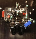
TSSA schematic from the post#1, built by sonnya, all together four transistors only and as you can see from the pics very promising results.
Regarding simplicity measures, the TSSA basic is even simpler design and according to Sonnya measurements, and I believe they are correct, its results are even better than JLH 10 class A amplifier. 😉
Attachments
Well thats not surprising, it was JLH himself that came up with that topology, he showed it even before he did this one in the late 60 s.
But now I feel duty bound to report that JLH thought that single ended amps ( or whatever we choose to call this topology ) - for reasons he did not understand - sounded more pleasant than fully symmetrical designs.
So much fun to play with basic-simple designs, choose one and than rocket it to the moon. 😀
Homemmoder thanks for the info, good to know, very important informations from the history we shouldn't forget. 😉
Homemmoder thanks for the info, good to know, very important informations from the history we shouldn't forget. 😉
But now I feel duty bound to report that JLH thought that single ended amps ( or whatever we choose to call this topology ) - for reasons he did not understand - sounded more pleasant than fully symmetrical designs.
Yes, but lateral mosfets used in TSSA basic weren't available back than hehe 😉
Last edited:
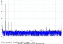
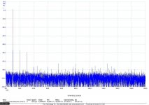
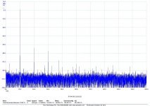
Mike I dont know about that, I have never seen him mention anything on this. l can tell you though if you build it as simple as in the Tssa thread it has even lower odd order harmonics, see the measurements.
He mentions that this symmetrical design has virtually no harmonics beyond 4th though when he showed it first.
He mentions that this symmetrical design has virtually no harmonics beyond 4th though when he showed it first.
l can tell you though if you build it as simple as in the Tssa thread it has even lower odd order harmonics, see the measurements.
Link to that thread?
One of the big advantages of simple topologies is that they are usually free of hidden local oscillations. In very complex circuits with many local feedbacks, like FB error correction, cascoded VAS, feedforward correction, triple EF, CFP stages etc. it may easily happen that the circuits have VHF local internal oscillations and even the author is not aware of them. It may need very complex instrumentation to find and cure such oscillations.
Doesn't even have to be oscillation - even a tendency towards ringing which is excited by the signal can seriously degrade the sound - but there are plenty of opportunities for this even in a simple amp - a small film bypass cap across an electrolytic is the classic example.
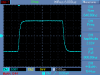
Nice wave form . . . . for the eyes
But the kind of spurious noise that can spoil the sound of a high end amp as you say are very difficult to measure - can be 1000 - 3000 times smaller than loudness of the signal at any moment - so would not be apparent on the scope even if it's there . . . .
But the ears can hear.
I recently added 1.0uF as bypass cap for an o/p stage, everything becomes much clearer but with strange character to the sound . When I add 0.1R in series with the 1.0uF then the sound is clean again.
In spice the effect ( and the cure ) can be clearly seen. Not sure how much this applies to an o/p cap but the laws of physics cannot be escaped - if you add C & L with low R you have high Q at resonant frequency.
Last edited:
In some tube pre-amps the bypass cap on the cathode resistor appears to degrade the sound audibly. Does this mean a 0.1R or similar resistor in series with the cathode bypass cap might prevent the sound from degrading ? Or would that have to be on an additional film cap across the bypass elco.
ashok,
The specific phenomena of which I speak above is created when a large cap is bypassed with a small film cap. The scenario you describe is different and it will depend on the value of the bypass cap as to whether there is an undamped resonance created. probably the resistance would naturally damp any potential resonance - It may be that like me you just don't like the "sound" of capacitors in the signal path.
Regarding the normal bypass scenario 0.1R is a good nominal value for 1.0uF across an electrolytic
If the bypass cap is smaller the resistance needs to be larger to damp the resonance created between the bypass cap and both the capacitors lead inductance - perhaps up to 0.4R for 0.1uF.
Because 0.1R can effectively damp 1.0uF I prefer this larger cap value as a bypass.
A 10uF cap may only need 0.05R. When you reach 100uF the problem is no longer significant.
It would seem that each of us is predisposed to like / dislike / not mind, different types of signal distortion so I honestly don't think there is a one sound that ideal for all which may explain the difference of opinion expressed above.
These things can be checked either with maths, with spice or with our ears. nominally you can assign 1nH per 1mm of lead length and you need to calculate, measure, guess the inductance inside the electrolytic cap.
Hope this helps
mike
Last edited:
Thanks for that explanation Mike. You are right about me not liking caps in the signal path. This is because I do hear differences between different types of caps and find they don't always behave exactly the same way in different circuits. Meaning that if X cap sounds better in circuit A , it's possible that X cap doesn't sound so good in circuit B ! I don't always simulate or measure these things but just try out the caps practically. Saves time and does involve the final listening test. Maybe some simulation can help identify a trend.
In fact some very simple inexpensive caps have produced some very good sounding amps. Sound so close to some botique caps that makes the expensive cap usage in that circuit redundant.
Cheers.
In fact some very simple inexpensive caps have produced some very good sounding amps. Sound so close to some botique caps that makes the expensive cap usage in that circuit redundant.
Cheers.
- Home
- Amplifiers
- Solid State
- JLH 10 Watt class A amplifier