Thanks AudioSan! Great looking amplifier. We are using the same boards, from kk-pcb.com? I didnt see the inductors in your powersupply. How does it sound?
I will need all the help i can get. I appreciate it.
I will need all the help i can get. I appreciate it.
Thanks AudioSan! Great looking amplifier. We are using the same boards, from kk-pcb.com? I didnt see the inductors in your powersupply. How does it sound?
I will need all the help i can get. I appreciate it.
yes that's right 🙂 i don't use inductors. i use resistors insted.
the sound is out of this world. it's calm, tight, relaxed, a bit tube warm and filled with power.
in one word. wonderful🙂
the heasinks is from heasinks USA by the way. a good and reasonable place to bye them. mine are 4x 10.080"x12" pr monoblock.
As I'm ordering some parts, here is my first question. Will this transformer work, or is there a better one out there?
The Antek 1000VA with 4 secondaries at 35V. I attached the spec sheet.
Since this toroid has 4 secondaries, I'm a bit confused as to how to connect them. Would I connect it as follows?:
1) Tie the red and black together for the input.
2) For the outputs: tie 2 green together and 2 blue together for 1 side
3) repeat step 2 for the other side of the power board.
Appreciate all your help!
Attachments
As I'm ordering some parts, here is my first question. Will this transformer work, or is there a better one out there?
The Antek 1000VA with 4 secondaries at 35V. I attached the spec sheet.
Since this toroid has 4 secondaries, I'm a bit confused as to how to connect them. Would I connect it as follows?:
1) Tie the red and black together for the input.
2) For the outputs: tie 2 green together and 2 blue together for 1 side
3) repeat step 2 for the other side of the power board.
Appreciate all your help!
you need to connect 2 and 2 outputs in paralell. then you wire those in series. blue-blue. green- green. and green-blue.
if it is a monoblock.
Thank you, that should be easy!
I saw Avel has a similar toroid with 2 secondaries instead of 4. If i can get my hands on those i will get them instead of the antek.
I saw Avel has a similar toroid with 2 secondaries instead of 4. If i can get my hands on those i will get them instead of the antek.
Well, I have made great progress on my Aleph 2 build, but I also have a few questions.
I have all components sitting on my desk.
Enclosure:
I have a very similar (if not the same) enclosure that JPDuarte has (see post #12).
PCB's:
I have the boards from kk-pcb.com (Pass Labs ALEPH-2 DIY amplifier PCB). The boards don't fit the enclosure (I need to somehow cut the PSU board and the driver boards). The PCB asks for 8 * 10,000 uF caps and RUGR3060 diodes.
Toroid:
For transformer I have the Antek 1kV / 35 V (Antek - AN-10435).
Questions:
1.) Do I need matching transistors (MPSA 18) on the amplifier board?
I did get 4 sets of 6 matching IRFP240's and 2 sets of 3 matching IRF9610's.
2.) Do the IRF9610's need to be mounted on a heatsink? How about the rectifier diodes (RUGR3060)? I don't see any room on the PCB to put a heatsink, but maybe I'm wrong.
3.) The recommendation is to reinforce the board with 1.4 mm copper wire in certain spots. I believe that comes down to 16 AWG, should I use solid or standed, or does it even matter?
Decisions for review:
1.) I think I will cut the PSU board right after the rectifier bridge. There are only 3 connections I have to make to the caps. An alternative is to cut it right were the coils are. Any preference? I'm still working on creating the internal platforms that JPDuarte has shown in post #30.
2.) From what I can see I also need to cut the boards with the IRFP240's. I think there are only 3 connections for me to make there. The pre-drilled holes in the heat sink don't match the spacing on my board. Options are: 1) drill/tap new holes (no idea how hard this is). 2) use a double sided adhesive, heat conductive and electrically non-conductive tape. This allows me to literally tape the IRFP240's anywhere on the heatsink, and I would probably align it with one screw to get a more secure connection so the tape doesn't have to carry the weight.
I am looking forward to any and all comments and suggestions.
Regards and happy holidays.
mpsa matching...no
3 9610's heat sink not nessary....however, i did put a little one on the ccs thinking the cooler they stay the better.
the other 2 are the input diff pair and should be thermaly attached.
as far as drilling and tapping..isnt to hard to do. i wouldent use tape them to the sink. even if the tape was just for that reason. but thats me.
another choice with your holes would be a long thick bar of somthing to clamp the fets to the sink using the holes you have.
the diodes, i would use small sinks, but thats me.
the wire used dosent matter, but you will use less solder with solid, the stranded will wick up solder. i like stranded.
mpsa matching...no
3 9610's heat sink not nessary....however, i did put a little one on the ccs thinking the cooler they stay the better.
the other 2 are the input diff pair and should be thermaly attached.
as far as drilling and tapping..isnt to hard to do. i wouldent use tape them to the sink. even if the tape was just for that reason. but thats me.
another choice with your holes would be a long thick bar of somthing to clamp the fets to the sink using the holes you have.
the diodes, i would use small sinks, but thats me.
the wire used dosent matter, but you will use less solder with solid, the stranded will wick up solder. i like stranded.
if you look at the output boards, you see that the bar system will not work.
Thanks for your replies! Since I'm a newbie it is very helpful to me.
Sakellogg:
I must admit I do not understand what you mean completely: 'ccs' and 'input diff pair'.
- I made a small heatsink for the diodes (L-shaped aluminum)
- I will put a small heatsink on the 9610's per your recommendation.
AudioSan, I appreciate your input. Hopefully my drill/tap exercise will allow me to attach the IRFP240's properly without having to go to plan B.
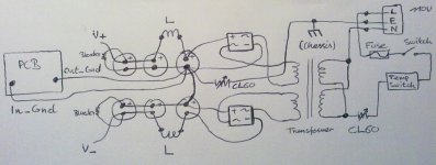
I will upload some photos soon. My focus at the moment is on getting the power section going according to post #145 (see picture attached).
Is it OK for me to move the on/off switch until after the 'temp switch' and 'CL60'? The sequence would be: socket, fuse, temp switch, CL60, on/off switch, transformer..
Thanks again for all your input.
Sakellogg:
I must admit I do not understand what you mean completely: 'ccs' and 'input diff pair'.
- I made a small heatsink for the diodes (L-shaped aluminum)
- I will put a small heatsink on the 9610's per your recommendation.
AudioSan, I appreciate your input. Hopefully my drill/tap exercise will allow me to attach the IRFP240's properly without having to go to plan B.
I will upload some photos soon. My focus at the moment is on getting the power section going according to post #145 (see picture attached).
Is it OK for me to move the on/off switch until after the 'temp switch' and 'CL60'? The sequence would be: socket, fuse, temp switch, CL60, on/off switch, transformer..
Thanks again for all your input.
Attachments
Would a 600VA 35/35v be sufficient per aleph 2 monoblock? I have one already that I can use and could buy one more.
Im not an expert but i think 600va would work, its the official spec. Please refer to the link below, which is the sort of official web site for Pass boards.
ALEPH 2 POWER SUPPLY
Upload some pics of your build if you have any. Im trying to learn from every picture.
Good luck.
ALEPH 2 POWER SUPPLY
Upload some pics of your build if you have any. Im trying to learn from every picture.
Good luck.
Thanks for the link. I haven't started my Aleph 2 yet. I have built an F5 and an Aleph 3 so far. Both of which I love. But they are not powerful enough to power some big 3 way speakers I built. I had acquired some parts for an aleph 5 build when I decided that I might as well build an aleph 2. Hopefully I'll have it done in the next 6 months or so.
Thanks for your replies! Since I'm a newbie it is very helpful to me.
Sakellogg:
I must admit I do not understand what you mean completely: 'ccs' and 'input diff pair'.
- I made a small heatsink for the diodes (L-shaped aluminum)
- I will put a small heatsink on the 9610's per your recommendation.
AudioSan, I appreciate your input. Hopefully my drill/tap exercise will allow me to attach the IRFP240's properly without having to go to plan B.
I will upload some photos soon. My focus at the moment is on getting the power section going according to post #145 (see picture attached).
Is it OK for me to move the on/off switch until after the 'temp switch' and 'CL60'? The sequence would be: socket, fuse, temp switch, CL60, on/off switch, transformer..
Thanks again for all your input.
hello. in the US it's not recomanded to have fuse and switch on hot wire. fuse on hot, switch on nutrual i think.
audiosan: small question: in you aleph 2, why do you create so many ground loops on your caps? isn't it better to just interconnect the first 2 and NOT the rest? to make a star ground? the ground loops can induce noise in your circuit...
AudioSan, I appreciate your photos. One picture or a thousand words. I can appreciate your craftsmanship after working on the amp myself and realizing how hard it really is. I will by buying the same connectors your have, it gives it a clean look. It looks like 1/4" connectors, and european style interconnect.
I will find out about the switch on neutral and fuse on hot. I just went with what I found in the previous posts.
I will find out about the switch on neutral and fuse on hot. I just went with what I found in the previous posts.
Team, the build is moving right along. Assembly of the boards has been easy, getting the enclosure assembled has been hard.
A couple questions:
- I have been using 12 and 14 gauge wire for the power section leading up to the amp board. What wire should I use for the amplifier section? it seems that 16 gauge would be as thick as fits in the pre-drilled holes to connect the main amp board to the mosfets?
- Should I try to drill and tap new holes in my enclosure to mount the mosfets, or should I not use the boards and do point to point wiring on the mosfets with the existing holes?
I appreciate any insights..
First checkpoint! I think I hit a first checkpoint and I would like to get your opinion if I should continue or not.
Good new: no fuses blown so far.
I have the project complete from the wall plug, to the fuse, switch, thermo, thermistor to the torroid transformer and to the rectifier bridge. I would like to know if the voltages I'm measuring are good, which means I can go to the next stage.
The torroid secondaries are 36.6 VAC and 36.7 VAC (supposedly 35V)
After the rectifier bridge I'm measuring 32.2 VDC and 32.2 VDC
The total draw at the moment is 0.06 Watts (several 10k ohm resistors to drain the caps).
Does this look good? I thought I was supposed to measure 36.6 *1.4 = ~51 VDC?
Thanks for your responses.
- Status
- Not open for further replies.
- Home
- Amplifiers
- Pass Labs
- My Dream Aleph 2 Coming True