Josip,
if you need those answers you are in the wrong thread.
This is a new amplifier topology, in it's early days/months of development.
We have no idea where the design will end up and even more troublesome, is how variations will develop alongside.
It you want reliable build answers, look at other amplifiers that have been successfully designed and tested and proved to work. And possibly more important "productionised" to allow incompetent builders to succeed where otherwise they will fail.
Last edited:
radio i think there is a misunderstand. I though you have built or on finished to built a BJT SSA version son you have yet un fonctionnel schematic with 2sc5200/sa1943...I don't have that's why i ask you for sharing yours eventualy.
Marc
Marc
Hi Lazy Cat.
I will build it.
I have bought all things I need for the Electrocompaniet verson, minus trafos.
When I build the SSA frontend I will have lots of transistors to spare.
Maybe a little SSA headphoneamp with crossfeed on +-15V if I manage to scale it down.
I allso have PCBdrawings for Frontend, outputboard, voltagereg and protectioncircuit,
but Am unable to attach it to a post.
I use express PCB for drawing, and will etch myself.
Sorry for my english.
Josip,
if you need those answers you are in the wrong thread.
This is a new amplifier topology, in it's early days/months of development.
We have no idea where the design will end up and even more troublesome, is how variations will develop alongside.
It you want reliable build answers, look at other amplifiers that have been successfully designed and tested and proved to work. And possibly more important "productionised" to allow incompetent builders to succeed where otherwise they will fail.
Ok thanks i will wait for experienced builders to give their blessing
The original the outputstage is taken from have 2X500VA trafos and is rated
2X120W/8 ohm ,2x200W/4ohm , 2X350W/2ohm , and stable at 1ohm.
Its a high speed, wide bandwith, low TIM amp based on Matti Ottalas findings.
2X120W/8 ohm ,2x200W/4ohm , 2X350W/2ohm , and stable at 1ohm.
Its a high speed, wide bandwith, low TIM amp based on Matti Ottalas findings.
The original the outputstage is taken from have 2X500VA trafos and is rated
2X120W/8 ohm ,2x200W/4ohm , 2X350W/2ohm , and stable at 1ohm.
Its a high speed, wide bandwith, low TIM amp based on Matti Ottalas findings.
That amplifier is already current limiting by 4 ohms..1 ohm stable ..?😕
I like this thread because of two things:
First, "two building blocks" were presented in basic topology info: SSA sym-diff CFL front-end and BIGBT output device, both very well practically tested, recognized as very stable and reliable, just what a DIY-er needs.
Second, simplicity of the SSA design is very appealing to many but just because there is no no-brainer cook-book recipe it is only available to experienced builders who knows and who dares. Like Nico in the first place, who immediately recognized benefits of the SSA design.
So the Q is, who dares next?
P.S. My current "work in progress" goes on this. I am sure that at the end, if something like that exists, there will be a few "Best of SSA" versions. 🙂
Last edited:
post626,
A.W. how do you arrive at that?
200W/120W = 1.67 ratio.
350W/200W = 1.75 ratio.
These are pretty good ratios indicating that the amp can easily drive a 4ohm speaker load.
Cordell suggests a ratio when halving the load resistance of >1.8
These figures are close.
But there appears to be a bit of rounding error. I would expect the 8:4 and 4:2 ratios to be swapped around. Had the 8r0 power been ~210W then the ratios would be believable and certainly indicate adequate current capability to drive a 4ohm speaker.
I like this thread because of two things:
First, "two building blocks" were presented in basic topology info: SSA sym-diff CFL front-end and BIGBT output device, both very well practically tested, recognized as very stable and reliable, just what a DIY-er needs.
Second, simplicity of the SSA design is very appealing to many but just because there is no no-brainer cook-book recipe it is only available to experienced builders who knows and who dares. Like Nico in the first place, who immediately recognized benefits of the SSA design.
So the Q is, who dares next?
P.S. My current "work in progress" goes on this. I am sure that at the end, if something like that exists, there will be a few "Best of SSA" versions. 🙂
LC post 347 is that schematic good ?
also ,
- post #224 dual mono PCB, Nico's version according to Nico sch, one pair 2SJ162/2SK1058 laterals
- post #227 single mono PCB, Alex's version according to Nico sch, one pair 2SJ162/2SK1058 laterals
- post #301 single mono PCB, Alex's version according to Miib sch, three pairs 2SJ162/2SK1058
Which one is Nico running with ...?
Last edited:
Lazy Cat,
Your design is excellent, but the 15V supplies you use to elevate the fb nodes are required only because the input devices are bjt devices.
Your circuit is very, very close to Jean Hiraga's Le Monstre, but the advantage topologically of a jfet front end is the joining of the sources of the input devices, making fb injection very much simpler.
I have been simulating variants of Le Monstre, and the performance is very similar to your circuit. I feel your SSA has the great advantage of being all bjt; comp jfets are very hard to find these days. But here is something to consider, this is a pretty good first and second stage for a conventional output stage, though my preference is for a diamond buffer.
Again, hats off to you, to Nico and to Alex_MM, who does brilliant pcbs!
Cheers,
Hugh
Attachments
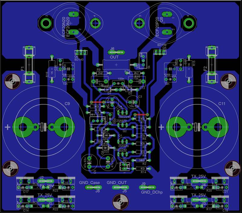
Hi Lazy Cat,
Can I replace ECF20N20/ ECF20P20 with 2SK135 /2SJ50?
Can we expect to see any time soon:
- SSA BIGBT High Performance, sch, PCB (single ch), separate PWS
Regards to all
Thanks for encouraging words Hugh. It was not a SSA lucky strike to me, on contrary a lot of logical thinking to resolved it like it is now. Complementary j-fet input is simplicity in its pure meaning, but to put BJT's instead was a challange to me. I started from a simple question: "How to put BJT's in CF diff input and arrange all DC working points in proper function?", so I came up with tha SSA. It is probably closest replacement to Hiraga's input and it is made from all BJT-s resulting in extreme low noise and wide bandwidth. SSA input's vital parameters are of so high performance that scalability to any kind of amp (VAS+output) as well as 0dB diamond output buffer presents no difficulties. As I already mentioned before, the limits are within designer's imagination. 🙂
LC post 347 is that schematic good ?
It should be in general, I am currently working on it. All the details will be presented soon. 🙂
Which one is Nico running with ...?
This one:
- post #224 dual mono PCB, Nico's version according to Nico sch, one pair 2SJ162/2SK1058 laterals
Hi Lazy Cat,
Can I replace ECF20N20/ ECF20P20 with 2SK135 /2SJ50?
Can we expect to see any time soon:
- SSA BIGBT High Performance, sch, PCB (single ch), separate PWS
Regards to all
Yes you can, but aren't 2SK135 /2SJ50 a little obsolete? Still, you can put them in action if you have them laying around. 😀
SSA BIGBT High Performance is a work in progress and will be presented soon.🙂
But you can overtake me with SCH, PCB, PWS. 😉
So i made corrections and modifications that you advise me :
Marc
Bravo Idefixes, you are planing a great PCB there. It will be a very nice SSA amp with TO-3 output pair.

- Status
- Not open for further replies.
- Home
- Amplifiers
- Solid State
- Simple Symetrical Amplifier