Hi!
Recently built a pair of near field monitors with Peerless 830875 and Seas h1189.
I'm so pleased with them that I decided to add another woofer and make them floorstanders.
Given that I have to build everything back, I want to complicate the design. And for this, I thought to make a time alignment for the drivers.
The problem is I do not know exactly how. I read that magnetic motors are placed in the same vertical plane. Is this true? What should I consider if it is not true?
Some people have reported in this forum that they successfully time aligned drivers by designing the speaker with a "sloped" baffle, at about 15 degrees. The goal is to align the acoustic centers, but determining exactly where that is without some measurements (e.g. impulse arrival times) is not likely to be very precise.
-Charlie
-Charlie
I would suggest to build an enclosure without time alighnment and build each section of the filter for each speaker separately.
Drive each section of the filter with a separate amplifier and add a digital delay using your computer with a 6 channel sound card as a source.
Play with the delay's between the various drivers until you are satisfied with the result and then calculate the phisical offset of teh drivers from the digital delay that you ended up with.
When you look at commercial designs, you will find that the offset of the drivers is not exactly the alighnment of the drivers, nor the alignment of the voicecoils. Also the delay in combination of the electrical parameters is part of the acoustical delay.
Thanks to all of you.
The slopped baffle design is interesting. But i´m trying to align them with a regular frontal shape.
I was thinking about using something like double or triple front panel for the woofers, but not for the tweeters.
What do you think about?
The slopped baffle design is interesting. But i´m trying to align them with a regular frontal shape.
I was thinking about using something like double or triple front panel for the woofers, but not for the tweeters.
What do you think about?
While the computer delay is an option, it may not be possible or even desirable as part of the system. Indeed neither may be the addition of more power amps.
Time aligning the drivers is a little more complicated then physically aligning the voice coils, it just doesn't work like that, at least not in the way you'd think.
According to what I've learnt the acoustic centre for a driver moves in position relative to the frequency it is reproducing. Therefore any 'aligning' be it physical or electrical is only relevant to that one frequency, or rather you could say frequency band because the acoustic centre will most likely remain within acceptable limits over certain frequency bands.
The same is also true for the crossover employed. These add in electrical phase shifts that correspond to physically moving the tweeter through the Z axis and the amount to which this occurs is highly dependant on the target transfer function. That is to say the 'delay' imparted by the electrical crossover component is different for different xover frequencies and slope types.
The only true time alignment can come from digital filters that posses the ability to compensate for any phase shift across the entire audio band. I believe this is what the FIR proponents are getting at with regards to the 'point' or the holy grail of why you'd go digital in the first place. A bit like saying, if you've got a digital crossover and haven't implemented a phase linearising FIR filter then why bother at all? Of course there are many reasons why one should bother, but some would say you've missed half of the point by ignoring it.
Ignoring the digital FIR solution, you cannot simply place the tweeter in one position and be done with it.
For a start the wave fronts that the different drive units are producing can only be truly coherent at one listening height. This is obvious when you think about it because moving up and down alters the relative distance that the sound waves have to travel from the tweeter and the woofer. This is why properly done coaxial drivers attract such a large following, as their vertical off axis response mirrors their horizontal off axis. That is (if properly designed) remaining flat and coherent as you go off axis, with only high frequency, beaming related droop showing. Rather then a non coaxial system that has the two drivers going in and out of phase with one another as you change the vertical listening axis, creating dips and troughs all over the place.
As we're talking about a non coaxial driver, this means you have to design your system around one preferred listening height.
Next on the agenda you have to choose what xover point and slopes you'd like to use. The H1189 (27TDFC) is a capable device and can operate at low xover points without a problem, this is a very good thing.
The peerless driver being a 6.5" mid/bass will start to beam quite early on and should ideally be crossed over as low as the tweeter can go. Also if you use Zaph's measurement of it's smaller brother, the Peerless 830873, as a guide line, it shows that the driver will probably exhibit a rising trend in it's third harmonic too.
To this end the two drivers are a good match for one another. Something like a 4th order around 1800hz or so, maybe lower if you don't mind pushing it some.
Keeping in mind your desire to 'time align' the design by altering the position of the tweeter in the Z axis, what I'd suggest you do is this,
Build a test box and mount the mid/bass at the top of the enclosure. Then place the tweeter on top of the enclosure, such that it can be moved forwards and backwards.
This will create all sorts of diffraction issues, so you will need to flush mount the tweeter in it's own baffle. The baffle should be the same width as the main enclosure and at least as high as the tweeter is wide.
You will then need to measure the drivers and design a filter for them, but rather then aiming for a phase coherent design (like you would if the tweeter was fixed in place on a flat baffle) you want to aim for getting the xover acoustic slopes as accurate as possible. That is as close as they can say to the 1800hz LRW 4th order I mentioned before.
After having done this you need to measure the drivers with the filter in place and measure for a reverse null. This should be done at your typical listening distance and typical listening height. You should then move the tweeter backwards by say 5mm and measure again. Keep moving and measuring until you've come up with the position that yields the best reverse null. Flip the polarity and you're done. The response should be flat, but could show some irregularities due to diffraction around the 'step' created by moving the tweeter backwards.
All that is left is to construct the final box.
Troel's Gravesen has done a study on tweeter and baffle mounting with regards to 'stepped baffles' and it can be found here.
There are of course more then one way to go about this, but if it was me, I'd start out by trying what I've suggested here.
That article is EXCELLENT!
I´ve read it and now i understand better how this works.
I´ll try some things from that article.
Thank you 5th element!
I´ve read it and now i understand better how this works.
I´ll try some things from that article.
Thank you 5th element!
5th Element's reply is one of the most accurate and concise responses I've seen in quite a while on a complicated speaker design topic.
A couple of comments.
1) Generally, the tweeter offset is usually 1 1/4" to 1 1/2" when all is said and done.
2) Ramiro77, are you building a TWW configuration? You stated "....I decided to add another woofer and make them floorstanders." If so, time aligning two woofers with one tweeter is more complicated, as the second woofer's relative location will have to taken into account, along with lobing concerns at the cross region. You may want to consider a WTW configuration, which then brings up significant diffraction issues. Mounting the Seas 27TDFC tweeter in an MCM waveguide, like John did at Zaph Audio, would help both the time alignment and diffraction issues. Also, he used a 2.5 TWW design, as shown on his website, with the lower woofer just playing bass frequencies to avoid lobing between the tweeter and the lower woofer.
Oh, I just noticed this again, you're most welcome and good luck with your design!
The wider the baffle, with a TMM, and the high/steeper the slopes are from the tweeter to the primary mid/woofer, the less the 0.5 woofer and the tweeter will interact with one another. Twinter is quite right in saying that the 0.5 woofer and tweeter could have some odd interaction issues that you'd rather avoid.
If you were using 4" wide cabinets with small drivers, baffle step would start as high as 1500hz and as the 0.5 driver is generally rolled off with a shallow slope it would most certainly contribute to output in the main crossover range. How much it would contribute would be determined by the cross between the main mid/bass and the tweeter of course.
If you're using the 830875 you've probably got cabinets around 8" /20cm wide, where baffle steps starts around 700hz, by then the 0.5 woofer should already be down 6dB, and by 2000hz, should be around 20dB down in level. This should be significantly well attenuated to not cause too many issues with the tweeter, if steep slopes are used.
Another way to configure the 0.5 woofer is to drive it and it's inductor after the crossover that feeds into the primary mid/bass. Naturally you need to reconfigure the xover for the primary driver for the halving of the impedance. What this does is provide the gentle slope of the 0.5 woofers inductor to compensate for baffle-step. But as the 0.5 woofer is being driven through the primary drivers crossover too, it adds in the extra attenuation that the primary crossover provides, helping even more to keep the 0.5 drivers contribution out of the way during the main crossover region
Of course you really need to simulate these for the best effect.
The wave-guide idea is a nice one and if you could design everything perfectly, so that the physical offset provided by the wave-guide would perfectly time align the system, for your preferred listening axis, then I think you'd be on to a winner.
5th Element's reply is one of the most accurate and concise responses I've seen in quite a while on a complicated speaker design topic.
Hmmm, 5th Element made some interesting points, but some that I would disagree with - see below:
While the computer delay is an option, it may not be possible or even desirable as part of the system. Indeed neither may be the addition of more power amps.
I can't see why "computer delay" would not be desirable, if executed properly. There are some interesting DSP crossover solutions like the MiniDSP that can provide any desired digital delay for loudspeaker crossover work. In my opinion, having one amplification channel per driver is optimum. Amplification is cheap, and coupling the driver directly to the output stage without passive components in between does have its advantages, as outlined in this article:
Active Vs. Passive Crossovers
Time aligning the drivers is a little more complicated then physically aligning the voice coils, it just doesn't work like that, at least not in the way you'd think.
According to what I've learnt the acoustic centre for a driver moves in position relative to the frequency it is reproducing. Therefore any 'aligning' be it physical or electrical is only relevant to that one frequency, or rather you could say frequency band because the acoustic centre will most likely remain within acceptable limits over certain frequency bands.
What you have written above is certainly something new to me. Can you expand on "what you've learnt". I do not agree that there is some frequency dependence to the acoustic center. I believe we are not talking about doppler distortion type issues, so I am not sure how frequency comes in to play - it's the "at rest" position that is of interest, since audio signals are AC and therefore the transducer's diaphragm is moving about this position.
The same is also true for the crossover employed. These add in electrical phase shifts that correspond to physically moving the tweeter through the Z axis and the amount to which this occurs is highly dependant on the target transfer function. That is to say the 'delay' imparted by the electrical crossover component is different for different xover frequencies and slope types.
OK, now you seem to have switched to talking about phase alignment, which is different from aligning acoustic center. Both will have an effect on the interference of the driver wavefronts in space, but in different ways so you cannot really lump them together. The acoustic center misalignment is frequency independent and this is why correcting it with digital delay (also frequency independent) is a good approach. Analog delay can be designed to have flat group delay up to some maximum frequency, but then the group delay falls back to zero. However, analog delay can still give very good results when it is designed and applied correctly.
But in the end of the paragraph above, you are absolutely correct in that each filter function that makes up a crossover has an associated phase response, as do the drivers themselves, and this can lead to phase leads or lags that cause undesired perturbations (peaks or nulls) in the frequency response. You need to model the entire system together to see how all the sound sources will combine at the listening position (and for power response everywhere).
The only true time alignment can come from digital filters that posses the ability to compensate for any phase shift across the entire audio band. I believe this is what the FIR proponents are getting at with regards to the 'point' or the holy grail of why you'd go digital in the first place. A bit like saying, if you've got a digital crossover and haven't implemented a phase linearising FIR filter then why bother at all? Of course there are many reasons why one should bother, but some would say you've missed half of the point by ignoring it.
Ignoring the digital FIR solution, you cannot simply place the tweeter in one position and be done with it.
Now I can't claim to know much about the particulars of implementing digital filters, but I have to disagree again about how one can properly align and cross over two drivers. There is not need to use esoteric digital signal processing as both can be done using analog circuits. The effect of driver phase can also be removed pretty easily in the analog domain. The only effect left to deal with is the phase response of the crossover itself.
For a start the wave fronts that the different drive units are producing can only be truly coherent at one listening height. This is obvious when you think about it because moving up and down alters the relative distance that the sound waves have to travel from the tweeter and the woofer. This is why properly done coaxial drivers attract such a large following, as their vertical off axis response mirrors their horizontal off axis. That is (if properly designed) remaining flat and coherent as you go off axis, with only high frequency, beaming related droop showing. Rather then a non coaxial system that has the two drivers going in and out of phase with one another as you change the vertical listening axis, creating dips and troughs all over the place.
As we're talking about a non coaxial driver, this means you have to design your system around one preferred listening height.
Next on the agenda you have to choose what xover point and slopes you'd like to use. The H1189 (27TDFC) is a capable device and can operate at low xover points without a problem, this is a very good thing.
Again, you hit the nail on the head above. The system has to be modeled including all sources of phase and amplitude deviation/response at the listening position (at a minimum). Then compensation and crossover networks must be designed to make the overall response of the system as flat and linear phase as possible.
So, I'd definitely like to see another post from 5th Element, since it seems like we have some different ideas about how to go about things. I imagine he has some perspective that he can lend to the thread, and this topic is one that I am currently studying. I am open to different ideas, even if I don't agree with them in their entirety.
-Charlie
Well you've certainly put some work before me!
Oh I 100% agree with this, you misinterpreted what I was trying to say though. What I was meaning is that using a PC as a music source and for xover work might not be desirable in ramiro77s system.
Using a PC as a music source is something I've been doing for a very long time, however having it handle the xover has never been flexible enough for my needs.
Yes, I agree, my system is entirely active too and I would more then encourage anyone to go that route. However considering ramiro77s initial post about doing something simple, like physically moving a driver a back a bit, I thought I'd expand upon that idea, rather then go into more complicated system designs.
RE DSP, I am in the process of designing a unit that takes I2S inputs, feeds it through an ADAU1445 (the top line model in the same family of chips the minidsp uses.) and then into many PCM1792s.
This was first brought to my attention I believe many years ago over on the Madisound discussion board. Later on I saw that Vance Dickason had mentioned this also in his loudspeaker design cookbook. He mentions this on page 113 of the 6th edition.
I quote
"The exact location of the driver radiating centre, or zero delay plane, can be somewhat of a mystery. When calculating the horizontal offset distance (or the amount of time delay caused by that distance) for crossover design purposes, the only important factor is the relative amount of offset and not the driver acoustic centres. A loudspeaker's acoustic centre varies with frequency and by definition is a function of the natural phase response of the driver."
End of quote.
In other words the variation in the acoustic centre is represented in the phase response you take when you measure the driver, thus this is factored into the crossover design (it'd have to be otherwise we'd end up with unpredictable results!).
Acoustic phase and electrical phase are one and the same thing. If you delay the electrical signal by 1ms, it's exactly the same as moving the driver backwards 34cm (all things being equal). We are not altering the waveform (hopefully) with either form of 'delay' we're simply delaying the onset of the wave front.
A driver has a natural acoustic response, this contains variations in both phase (the relative acoustic centre) and amplitude. An electrical filter also posses the same properties (linear phase filters not withstanding!). The drivers acoustic properties aren't going to change once the cabinet design has been finalised and it's up to the delay imparted by the electrical filter to phase align the drivers present in the system.
This is of course one of the reasons why passive filters are seen as being so limited. In the attempt to phase align the system you're usually forced into asymmetric slopes or less then perfect xover points. If electrical (either analogue or digital) delay is on the cards then you suddenly have a lot more design freedom (or a much easier job designing systems). Of course the use of a stepped baffle can accomplish the same thing, but the size of the step has to be incorporated into the overall system design, just like the amount of electrical time delay required to do the same thing has to factor into it not only the physical offset between the drivers, but the type of filters used also.
I can't see why "computer delay" would not be desirable, if executed properly.
Oh I 100% agree with this, you misinterpreted what I was trying to say though. What I was meaning is that using a PC as a music source and for xover work might not be desirable in ramiro77s system.
Using a PC as a music source is something I've been doing for a very long time, however having it handle the xover has never been flexible enough for my needs.
There are some interesting DSP crossover solutions like the MiniDSP that can provide any desired digital delay for loudspeaker crossover work. In my opinion, having one amplification channel per driver is optimum.
Yes, I agree, my system is entirely active too and I would more then encourage anyone to go that route. However considering ramiro77s initial post about doing something simple, like physically moving a driver a back a bit, I thought I'd expand upon that idea, rather then go into more complicated system designs.
RE DSP, I am in the process of designing a unit that takes I2S inputs, feeds it through an ADAU1445 (the top line model in the same family of chips the minidsp uses.) and then into many PCM1792s.
What you have written above is certainly something new to me. Can you expand on "what you've learnt".
This was first brought to my attention I believe many years ago over on the Madisound discussion board. Later on I saw that Vance Dickason had mentioned this also in his loudspeaker design cookbook. He mentions this on page 113 of the 6th edition.
I quote
"The exact location of the driver radiating centre, or zero delay plane, can be somewhat of a mystery. When calculating the horizontal offset distance (or the amount of time delay caused by that distance) for crossover design purposes, the only important factor is the relative amount of offset and not the driver acoustic centres. A loudspeaker's acoustic centre varies with frequency and by definition is a function of the natural phase response of the driver."
End of quote.
In other words the variation in the acoustic centre is represented in the phase response you take when you measure the driver, thus this is factored into the crossover design (it'd have to be otherwise we'd end up with unpredictable results!).
OK, now you seem to have switched to talking about phase alignment, which is different from aligning acoustic center. Both will have an effect on the interference of the driver wavefronts in space, but in different ways so you cannot really lump them together.
Acoustic phase and electrical phase are one and the same thing. If you delay the electrical signal by 1ms, it's exactly the same as moving the driver backwards 34cm (all things being equal). We are not altering the waveform (hopefully) with either form of 'delay' we're simply delaying the onset of the wave front.
A driver has a natural acoustic response, this contains variations in both phase (the relative acoustic centre) and amplitude. An electrical filter also posses the same properties (linear phase filters not withstanding!). The drivers acoustic properties aren't going to change once the cabinet design has been finalised and it's up to the delay imparted by the electrical filter to phase align the drivers present in the system.
This is of course one of the reasons why passive filters are seen as being so limited. In the attempt to phase align the system you're usually forced into asymmetric slopes or less then perfect xover points. If electrical (either analogue or digital) delay is on the cards then you suddenly have a lot more design freedom (or a much easier job designing systems). Of course the use of a stepped baffle can accomplish the same thing, but the size of the step has to be incorporated into the overall system design, just like the amount of electrical time delay required to do the same thing has to factor into it not only the physical offset between the drivers, but the type of filters used also.
Well you've certainly put some work before me!
Oh I 100% agree with this, you misinterpreted what I was trying to say though. What I was meaning is that using a PC as a music source and for xover work might not be desirable in ramiro77s system.
Using a PC as a music source is something I've been doing for a very long time, however having it handle the xover has never been flexible enough for my needs.
Yes, I agree, my system is entirely active too and I would more then encourage anyone to go that route. However considering ramiro77s initial post about doing something simple, like physically moving a driver a back a bit, I thought I'd expand upon that idea, rather then go into more complicated system designs.
RE DSP, I am in the process of designing a unit that takes I2S inputs, feeds it through an ADAU1445 (the top line model in the same family of chips the minidsp uses.) and then into many PCM1792s.
This was first brought to my attention I believe many years ago over on the Madisound discussion board. Later on I saw that Vance Dickason had mentioned this also in his loudspeaker design cookbook. He mentions this on page 113 of the 6th edition.
I quote
"The exact location of the driver radiating centre, or zero delay plane, can be somewhat of a mystery. When calculating the horizontal offset distance (or the amount of time delay caused by that distance) for crossover design purposes, the only important factor is the relative amount of offset and not the driver acoustic centres. A loudspeaker's acoustic centre varies with frequency and by definition is a function of the natural phase response of the driver."
End of quote.
In other words the variation in the acoustic centre is represented in the phase response you take when you measure the driver, thus this is factored into the crossover design (it'd have to be otherwise we'd end up with unpredictable results!).
Acoustic phase and electrical phase are one and the same thing. If you delay the electrical signal by 1ms, it's exactly the same as moving the driver backwards 34cm (all things being equal). We are not altering the waveform (hopefully) with either form of 'delay' we're simply delaying the onset of the wave front.
A driver has a natural acoustic response, this contains variations in both phase (the relative acoustic centre) and amplitude. An electrical filter also posses the same properties (linear phase filters not withstanding!). The drivers acoustic properties aren't going to change once the cabinet design has been finalised and it's up to the delay imparted by the electrical filter to phase align the drivers present in the system.
This is of course one of the reasons why passive filters are seen as being so limited. In the attempt to phase align the system you're usually forced into asymmetric slopes or less then perfect xover points. If electrical (either analogue or digital) delay is on the cards then you suddenly have a lot more design freedom (or a much easier job designing systems). Of course the use of a stepped baffle can accomplish the same thing, but the size of the step has to be incorporated into the overall system design, just like the amount of electrical time delay required to do the same thing has to factor into it not only the physical offset between the drivers, but the type of filters used also.
OK, now I see the context in which you were making some of these comments. So they make more sense now.
Regarding your quote of Diackason, note that he mentions "loudspeaker", and this implies two or more drivers. In that case, yes, the acoustic center is varying with frequency, but this is only because each driver reproduces only a portion of the entire 20-to-20 and as you cross from one driver to the next, the acoustic center moves along with the signal. For a single driver, I do not believe that the acoustic center has any frequency dependence.
I will repeat my previous statement that phase response and acoustic center are two different things. Its' true that both do impact the relative phase difference between two or more drivers, however the two can't really be interchanged. The phase response of each driver is frequency dependent and has to do with the high pass filter characteristic of the driver. The delay resulting from acoustic center offset is frequency independent, however constant delay implies frequency dependent phase rotation. I guess you are looking at it from a phase perspective - the phase is changing with frequency, but this does not mean that the acoustic center is frequency dependent. Constant delay (from a frequency independent acoustic center) means the derivative of the phase is constant with frequency, thus there is continual phase rotation.
In the final analysis, it looks like we are on the same page here.
-Charlie
Charlie, I think I'm with 5th on this. Your assumption would be correct if the driver was a perfect radiator, but we know it isn't.
From what I've seen, the various flexing modes of the cone seem to mean that as frequency goes up, the radiation seems to be produced nearer and nearer to the centre, (or extremeties of the whizzer cone, if attached). So it's quite possible that acoustic centre could shift with frequency.
I am, however, prepared to be proven wrong. 😉
Charlie, I think I'm with 5th on this. Your assumption would be correct if the driver was a perfect radiator, but we know it isn't.
From what I've seen, the various flexing modes of the cone seem to mean that as frequency goes up, the radiation seems to be produced nearer and nearer to the centre, (or extremeties of the whizzer cone, if attached). So it's quite possible that acoustic centre could shift with frequency.
I am, however, prepared to be proven wrong. 😉
It's my opinion that a driver should NOT be operated in the region far above the "pistonic" operation regime, e.g. NOT where cone breakup is going on, or where the radiation is coming mostly from the center of the cone.
I was operating under the assumption that the multi-way loudspeaker under discussion has drivers operating that way (except possibly the tweeter at the top of its range). In that case, I don't think that your argument applies. Perhaps to some full range drivers, though.
-Charlie
Regarding your quote of Diackason, note that he mentions "loudspeaker", and this implies two or more drivers. In that case, yes, the acoustic center is varying with frequency, but this is only because each driver reproduces only a portion of the entire 20-to-20 and as you cross from one driver to the next, the acoustic center moves along with the signal. For a single driver, I do not believe that the acoustic center has any frequency dependence.
This isn't the way it is described in the book, he is talking about a single driver.
I will repeat my previous statement that phase response and acoustic center are two different things.
Lets look at this from a different perspective.
The measurement of phase during the design process is simply a representation of any of the delay characteristics that the driver itself represents. Phase in itself doesn't naturally exist and is something that we as humans have invented as a way of usefully describing this delay. Or, we have invented as a way of describing the relative delay between a fixed reference point and something that we are specifically interested in. The measured phase and it's described time delay are by nature frequency dependant, as the wavelength and thus the time of the delay, changes with respect to its given frequency. I think this is what you were saying in your last paragraph, but in a different way?
I must admit I am not technically minded when it comes to the mathematical proof or theory of how all of this is exactly working and I am not quite sure how you calculate or physically describe the reason for the acoustic centre shifting. According to Vance this isn't simply the acoustic centre shifting, as pinkmouse described, with respect to the part of the cone the sound is radiating from, there's more to it then that. But it could simply be describing how the phase of the driver shifts with respect to the fixed microphone position and as the phase measurement is frequency dependant, we see a phase shift re/ frequency.
Vance then goes on to say that for most intents and purposes one can assume that the driver radiates from a point just in front of the voice coil. He also goes on to say that any variations in the acoustic centre are made academic once the filter is in place. This makes sense as the role of the filter is to bring the two drivers into phase alignment. Although I think it should be noted that this is only around the crossover point.
Obviously the two drivers on a stepped baffle could be physically aligned so that when filter-less, the region between 1-3khz could be decently coherent. However once you filter the drivers this physical alignment would be wrong. Now of course you could start to go for asymmetric slopes to bring them into phase alignment, or you could keep your symmetric slopes and physically move the tweeter to bring the drivers back into phase with one another. This was the point I was trying to get at earlier, where the required physical offset for the tweeter is entirely dependant on the xover used.
Does that make sense?
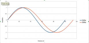
The kind of thing I'm visualising, although this cannot quite describe what's going on, is something like this.
Where we could take the origin to equal the microphone position. The loudspeaker would be placed 1 meter away, which would correspond to the wavelength of a 340hz wave. Then as we use a 300hz wave, the wavelength is obviously longer and further away then 1 meter. The mic position cannot change as this is our reference point, so as a result the calculated acoustic centre moves by X and that would be represented in degrees in some way on a phase plot.

Attachments
A point radiator in a fixed position with frequency dependent phase is a simpler approximation of a real driver than a point radiator with frequency dependent position. At least if you're trying to model the time domain behavior over a large solid angle. It's not, however, generally sufficient to consider the driver's lowpass characteristic and breakup. The highpass from suspension resonance and enclosure behavior affects the phase response as well and is more difficult to deal with as it's lower in frequency and hence requires larger physical offset or places greater demands on analog or digital correction. The audibility threshold for group delay rises significantly in the bass so this isn't as much of a problem as it might initially seem. But it's been my experience linearizing phase below 40Hz produces small but pleasing improvement.
The case of breakup in a larger full ranger is interesting. I haven't actually measured one but my mental model of the behavior aligns with what pinkmouse is describing. I tend not to be real keen on trying to shoehorn an acoustically large radiator into an acoustically small approximation though.
The case of breakup in a larger full ranger is interesting. I haven't actually measured one but my mental model of the behavior aligns with what pinkmouse is describing. I tend not to be real keen on trying to shoehorn an acoustically large radiator into an acoustically small approximation though.
In practice it depends on what you need to align. Since alignment of the back wave isn't important and crossover orders are usually low, typical two way box speakers can be aligned pretty well down to where the phase from the woofer's Fs or port tuning becomes significant (as you've observed the box and TW crossover have to be designed together). Box three ways are a fair bit harder and the approach doesn't work well with dipoles. As Charlie alluded to a fair number of things can be patched up with IIR delay equalization---the Orion ASP is an analog example of injustice to the back wave---as well as with digital delays. However, FIR operations at low normalized frequency are quite expensive and IIR delays are quite difficult to implement at high normalized frequency. If a crossover with a third order slope one side is acceptable you can use subtractive delay and IIR equalization to get fairly linear phase out of a stream based DSP like the ADAU1445 above a few hundred Hz. Phase linearization in the 20-40Hz range can be brute forced with FIR if you subsample but is still hard to pull off on a SigmaDSP. One can throw more expensive hardware at it but it's easier to switch to windowed FFTs or time reversed IIR (analog not being stable and physical offsets of a few meters usually being impractical).The only true time alignment can come from digital filters that posses the ability to compensate for any phase shift across the entire audio band.
Last edited:
I've looked a little into FIR filters and as you say you need an impractical number of taps for low frequency work.
I've never really investigated how you apply phase correction to an already implemented system. As you've got some experience on this could you possibly describe the process? And how do you go about measuring the compensation required for low frequency work? I'd have thought this requires an anechoic chamber or similar, or do you do it via simulation?
I intend to implement my 4 way system via the 1445 using typical filter topologies, with state variable and biquads. I suppose what I'd want to do is then add a filter before the crossover to linearise the phase. Is this a practical way to proceed on this?
OK, I looked up the passage in Dickason's book (which was very vague) and then checked out paper by Heyser that he references. I happened to find both parts of it on the web. I am carefully reviewing that material and I will try to post a follow up over the weekend.
-Charlie
-Charlie
- Status
- Not open for further replies.
- Home
- Loudspeakers
- Multi-Way
- Woofer + Tweeter: Physical time alignment