Good topology, Joachim. First used by Harris Associates in some of their op amps. Your version is a little over the top, however. I generally use less parts, or parallel them.
Last edited:
Yes, this topology is not new. I only tryed to max it out. In simulation we also tryed current mirrors on the input and bootstrapped current mirrors in the VAS but settled on this one after much head scratching.
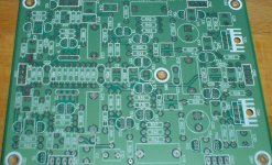
I usually design parallel symmetric but this one was designed to replace conventional Opamps so i neaded a diffential topology. Yes, i know, parallel symmetric, diffential can be done too but then the amount of active parts is even doubled and this one is already 9 x 6 cm in size.
I usually design parallel symmetric but this one was designed to replace conventional Opamps so i neaded a diffential topology. Yes, i know, parallel symmetric, diffential can be done too but then the amount of active parts is even doubled and this one is already 9 x 6 cm in size.
Yes, I too, have needed an OP-AMP and used a single diff pair to make it. I have used this design for 3 master tape recorders, and two 8 channel boards. One helped record a number of direct disc masters for Crystal Clear Records. We always need 'building blocks'. Of course, at each juncture, I have tried to inject a quality IC, in order to simplify design even further. First in 1970, with the HA911, later in 1978 with the TDA1034, and just about everything that comes along, in general. So far, all discrete, especially with jfets is better.
The design looks familiar for the most part. It doesn't look as expensive as many of the circuits we see running around here (or as the circuit I used for the NuForce preamp which is not an expensive preamp). The folded cascode should make it easy to stabilize.
1) The cascode bias will limit the common mode range and the GD voltage (and leakage) will be affected by the common mode voltage adding a nonlinearity.
2) A trimpot across the 33 Ohm source resistors will allow offset trimming. If the input pair are coupled and pretty close the offset drift with voltage and time will be pretty small. I don't know if its a better solution than adjusting the drain currents but it has worked well for me.
3) I know John would rather see FETs for the current sources. He can explain why if he choses
4) You have a cascode on Q7 but not Q8. Why?
5) Are blue LEDs quiet? I had a problem in the past where red led's were photosensitive and allowed noise and hum into the circuit. I have avoided them since. Are these newer devices not photosensitive any more?
I would like to ask John Curl about the Parasound preamp flagship, Halo JC2. What is the reason of relatively poor CCIF IMD result (3rd order distortion component), as seen in
http://www.stereophile.com/images/archivesart/308Parfig6.jpg
(it is only 3Vpeak to 200kohm, i.e. very light load and quite low output amplitude)
and early distortion rise, see
http://www.stereophile.com/images/archivesart/308Parfig2.jpg
Is the issue in a poor dynamic linearity of the simple MOSFET output stage (extremely non-linear capacitances)? I would expect more from full balanced design with very high supply rail voltages, and high idle current.
Thanks and best regards,
The Parasound JC-2 preamp is designed to be a BUILDABLE preamp that would perform fairly well, be made 6000 mi away from the designer, and have a lot of 'features'. It is NOT a BLOWTORCH, and it never will be.
I would take care, if I were you, PMA, your input borders on professional rudeness.
I would take care, if I were you, PMA, your input borders on professional rudeness.
I would also like to point out that PMA's measurement point would be 800W into 4 ohms, if it were used with a pair of JC-1 power amps, as it was designed to do. NOW, what about that 3'rd harmonic distortion?
Yes i have seen designs here that whould be nearly imposible to make commercially. The level of skill that some people show here in their DIY projects is amasing.
I am aware of the common mode range. We decided against a trimpot. One posibilty whould be to use a pot first and when the values are set, replace with fixed resistors.
The input transistors are matched doubles in one case anyway.
The constant current sources have been discussed at lenghth and my original design had red or green Leds with a lowpass filter to shunt the noise. The engineer that helped me with simulation was sure though that the blue Leds are quiet. Yes, a red Led has lower dynamic impedance ( around 5 Ohm i asume ) but only drops maybe 1.5V so you need a string for more voltage and then you end up with double or triple of that. I have made some good experiences with IR Leds and have some that are extremely "steep" so the voltage changes very little with current. They drop only 1.25V though. I have not experienced photosensitivity so far but i may have not looked carefull enough. There are active devices on the market for voltage reference with even lower dynamic impedance of less then 1 Ohm. I know that, but Leds are based on a quantum effect and they shine so nicely also giving me information if the circuit works. Maybe i am a bit romantic. Concerning the topology ( point 4 in your post ) i can not excactly remember how we arived at that. We tryed out more cascoding, mirroring, bootstrapping etc. but this circuit worked to our satisfaction. When i talk about the cost of making it, it is not only the amount of parts but the quality of parts that can be very expensive in the case of Vishey Z-Foils and the like. With standart parts the highest cost comes from the input tansistors. I buy them for around 10,-€ each here including shipping and tax. Maybe in quantity they are much cheeper or you have a better deal. And last not least, the layout is very generous ( 6 x 9cm ) so for example 6 of them to make a preamp with phono takes a lot of real estate and most of the cost is in the cabinet noverdays i am afraid.
P.S. Voltage Noise performance of this discrete Opamp is good but not outstanding. I whould not make an MC phonoamp with it. Parallel symmetric has a 6dB noise advantage there.
While I do not believe that PMA had this in mind, I would like to talk a bit about 3'rd harmonic distortion.
Many here fear 3rd harmonic distortion as if it were easily audible. It is not, and I can prove it.
I know this from decades of designing master tape recorders, from Ampex, to Mobile Fidelity, to Wilson Audio.
Do you know that originally, back in the 1950's with Scotch 111 mastering tape, 0 Vu was 1% 3'rd harmonic?
When I worked at Ampex, in 1968, the 3'rd harmonic distortion level at 0 Vu had dropped to about 0.7%. In the 1970's the 3'rd harmonic distortion at 0 Vu dropped, BUT many recording engineers decided to change the sensitivity of the Vu meter in order to get lower noise, and brought the 3'rd harmonic distortion back up to early levels!
So anyone who has heard a master tape, cassette tape, vinyl record or CD or even SACD, based on an analog master tape, can be promised at least 1% 3rd harmonic distortion virtually all the time when playing a selection. Ever notice?
Now, here is low level 3'rd harmonic distortion at 800W per channel into the loudspeaker system. Do you think this will be audible? Lots of luck!
Another way to get to the same place (almost) as John's JC2 phono stage http://rbsfm.ej.am/Downloads/Datasheet/LH/LH0032.PDF (but with bipolars on the output). The package is a little larger.
Looks almost like a discrete-on-a-chip 🙂 I'd like to play with some of these but probably it's either very expensive to find or unobtanium already.
jan didden
5) Are blue LEDs quiet? I had a problem in the past where red led's were photosensitive and allowed noise and hum into the circuit. I have avoided them since. Are these newer devices not photosensitive any more?
Forward biased, they never have been. I posted some results on this a few years ago with an intense light source hitting them. Zero difference compared to dark, as physics would predict. My tube phono stage is one of the quietest ones out there and there's an LED effectively in series with the input as well as in the succeeding stage.
I pointed at quite different result of the 3rd CCIF 19+20kHz distortion component compared to FFT 1kHz 3rd order component. The CCIF plot is measured into very light load (200kohm), that means that the HF non-linearity is inherent to the design. This is not any rudeness, but technical discussion. If the 3rd order component was constant with frequency, and load, and well below 0.01%, then it would probably be inaudible. Now, when it changes with frequency and load, and attacks levels of 0.01% orders and above, it may become audible. Listening comparison is always needed, one instrument without comparison would be considered very fine, I believe. There's a lot of listener's tastes, and no review would give enough 'sound description'. Anyway, measurements are comparable.
Again, we are trying to find -160dB PIM or -140dB of the 7th harmonic, but -80dB CCIF 3rd is considered fine in a line level stage (I guess CTC BT may have even more distortion) . To me, this approach is not correct. If we give a closer look to the figure 6, we can see the 7th order component as well, though low, about -115dB. So it is not a 'No 7th design'.
Again, we are trying to find -160dB PIM or -140dB of the 7th harmonic, but -80dB CCIF 3rd is considered fine in a line level stage (I guess CTC BT may have even more distortion) . To me, this approach is not correct. If we give a closer look to the figure 6, we can see the 7th order component as well, though low, about -115dB. So it is not a 'No 7th design'.
i know, parallel symmetric, diffential can be done too but then the amount of active parts is even doubled and this one is already 9 x 6 cm in size.
Adds an inch on both sides.
(added nomenclature is often longer, such as PDXB™ and DCCA™ for this one.
 )
)Attachments
Again, PMA, the Parasound JC-2 is designed to do the job, and it does it.
There is an apparent weakness in this sort of design approach that is probably due to using differential jfet input with dual feedback. While the design is inherently balanced, 3'rd harmonic is generated from the second harmonic inherent in each input jfet. This is where I would look first, if I were to attempt to address it. My better designs, such as Vendetta, CTC Blowtorch, or the new Orion preamp from Constellation, use 10 ma or more current in EACH jfet differential pair to improve input linearity. If you have a solution for this, without adding significant extra complexity, I would appreciate it. If not, then you are just bringing it up to compromise my reputation.
However, I am fully aware that the JC-1, CTC, or even the earlier Vendetta designs are ALL designed for approximately .01% (-80dB) distortion at 2V output. Since, this is a CLASS A design, the 3'rd harmonic distortion will rise or drop as the square of the output voltage, so, at 1V, I would expect .0025% (-92dB) 3'rd harmonic, and this would be 100W out into 8 ohms through each JC-1 or ANY other THX rated amplifier. Loud enough for you? Finally, at 1W out or about 90 spl from my direct radiator loudspeakers, I would expect 0.000025% (-132dB). Please check my math, I would not wish to understate the amount of distortion at each level.
Now really, is this such a problem? Perhaps, other factors take precedent at ALL working levels?
Adds an inch on both sides.
(added nomenclature is often longer, such as PDXB™ and DCCA™ for this one.
Wassat? (as we say in Texas)
- Status
- Not open for further replies.
- Home
- Member Areas
- The Lounge
- John Curl's Blowtorch preamplifier part II