OK, got it.
Thanks for the link, Great info. I think I may have to read it a couple more times to really get my head around it.
Resistor value not critical? Can you explain what is happening when this combination is used?
Thanks, Scott
Thanks for the link, Great info. I think I may have to read it a couple more times to really get my head around it.
Fit a resistor//diode//inverse diode in the line between feedback and pin
Resistor value not critical? Can you explain what is happening when this combination is used?
Thanks, Scott
most seem to adopt 10r from Signal Ground to Power Ground.
I have seen 1r0 all the way to 100r used here.
The diodes are there to limit the voltage on the RCA barrel and the far end of the interconnect if a high current flows into the RCA Signal Ground.
1N4001 will pass many tens of amperes for a few milliseconds and should last long enough to blow a mains fuse. The 10r without the diodes would burn and leave the high voltage on the equipment.
I put a .1uf polyprop across the supply pins and the 100uf electrolytics in line off the pot.
DC in both channels about .05 and no more weird stuff at max gain.
AWESOME! Thanks for the tips guys! Scott
Well, not quite🙁
I just finished my third and most complete version of this circuit with all the recent updates. I feel like I've done a very thorough job of keeping it clean and organized.
I'm still having serious problems when the gain stage is plugged into the gainclone.
Here are some test results on the outputs of the circuit
TEST 1 Nothing connected to gain stage rca in and outs
0 gain -.005 vdc left channel -.011 vdc right channel
100% gain -.006 vdc left channel -.012 vdc right channel
TEST 2 6 ft generic interconnects from gain stage to gainclone inputs
0-75% gain -.07 vdc left -.09 vdc right
75% - 100% gain -.006 vdc left -.012 vdc right
Notice the dc is much lower with max gain😕
TEST 3 3 ft Monster cable interconnects from gain stage to gainclone inputs
0-90% gain -.02 vdc left -.03 vdc right
90-100% gain sporadic changes in both channels between -.01 to -.04 vdc
TEST 4 same as 3 plus 3 ft Monster cable plugged into input [ no source ]
0-100% gain -.045 vdc left -.045 vdc right
TEST 5 same as 4 plus cd player on input
0-100% gain -.047 vdc left -.047 vdc right
The Gainclone with any other source plugged in has very low offset. You can turn the volume all the way up and not hear a thing or see the woofers move. With the gain stage plugged in and the gainclone volume at 50% there is -.57 vdc on the speaker outputs. At 98% gainclone volume there is -.8 vdc and when you hit 99% it goes to + 4.4 vdc. You can see the speakers suck in as you turn the volume up and right before full volume the cones reverse and about blow out the front of the speakers. I get none of this behavior with any other source hooked up except for the tone control circuit, I don't have specific numbers but visually you can see the woofer do the same thing.
Both the tone control and the gain stage are being powered by the gainclone snubbed psu.
Could this have something to do with the problems. Maybe I'm hooking it up wrong.
Another odd problem I've had with all three gainstage circuits is the pot doesn't have any effect between 0 and 75%. You can't hear any change in the volume until you get above 75% then it increases nicely. I reversed the connections on the pot and it worked nicely from 0-100 but the action was backwards. It got louder as you turned it down.
when you have no source connected the output offset is low and acceptable.
When you connect a source the output offset increases and varies with contol knob rotation. This tells you that you have DC from source to amplifier and the amplifier is not protecting the speakers from that errant DC.
Fix the source or fix the amplifier.
When you connect a source the output offset increases and varies with contol knob rotation. This tells you that you have DC from source to amplifier and the amplifier is not protecting the speakers from that errant DC.
Fix the source or fix the amplifier.
This thread has got quite long and I think we would have to see the full circuit now.
Some pointers though... your GC must be DC coupled throughout (including the feedback return) for the DC on the speaker to increase as the volume is altered. Normally the feedback is AC coupled to ground to give unity gain at DC.
If it is AC coupled it can not amplify any DC present at the input but simply passes that DC value on to the output.
The sudden "reversing" of the cone is due to the GC either limiting in some way or the excess current is dragging one rail down and again causing unpredicatable behaviour.
I build the GC exactly as Peter Daniels did in His Commercial Gainclone Kit-Building Instructions. This post seems relevant http://www.diyaudio.com/forums/audio-sector/123003-commercial-gainclone-kit-building-instructions.html#post1508778
I went with the piece of wire for R1
I'll draw out the complete gain stage schematic and post it up later.
I went with the piece of wire for R1
I'll draw out the complete gain stage schematic and post it up later.
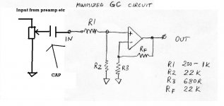
If you mean as in post #3 in that thread then that is why the amp behaves as it does.
Normal good practice for a power amp is to AC couple the input, and that gives complete protection against a source/preamp etc with a DC offset.
Also AC coupling the feedback return (R3 in tht circuit) ensures the power amp itself has no DC gain and no problems with internal offset issues.
Normal good practice for a power amp is to AC couple the input, and that gives complete protection against a source/preamp etc with a DC offset.
Also AC coupling the feedback return (R3 in tht circuit) ensures the power amp itself has no DC gain and no problems with internal offset issues.
10uf is fine for the input cap... that will essentially fix the problem.
To AC couple the feedback a cap is added in series with R3... it would have to be an electroylitic of around 220 to 330uf. To small a value and the low frequency response is reduced... but it's pretty standard practice to fit one.
RF and R2 should always be equal for minimum offset... not having caps fitted throws that out of the window... I'd fit them.
As the voltages are indeterminate and small it's best to measure across the cap when fitted and in use and position accordingly... there's no right and wrong answer here as the offset can be either way .
I fit the 10uf's on the GC.
Didn't fix the problem, just changed the symptoms a bit.
The GC with a cd player or a phono pre plugged in has .07 on the left and .10 on the right regardless of where the volume knob is.
The volume is wired in as an attenuator before the amp.
When I hook up the gain stage all hell breaks loose 😱
The GC has a decent offset around - .08. As I turn up the volume knob it decreases -.07,-.06,-.05 all the way to 000 at about 50% volume. Then it switches to the positive side and moves up to as the pot goes up. At 75% there's about 2 volt. At full volume it goes crazy and hits 11 volts.
I'll post the exact gain stage circuit later. There must be something fundamentally wrong with the way I'm putting it together.
Thanks for all the help, I've learned a boat load from you two guys. I really appreciate it.
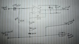
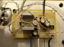
Here's the circuit exactly like I have it. It's on a Radio Shack proto board layed out very much like it is drawn. As suggested by Andrew, the diodes just before power ground are 1N4001 and the R is 10 ohm.
If you look at the photo of the board you'll see I used the two traces that run down the middle as the ground plane. They connect together at the end on the right, run through the D/R/D to a pin for power ground.
The 49720 straddles the ground plane. I bent the legs so that 4 and 8 are on the same side. You can see the +/- 15v attached at the center bottom.
The feedback resistors are soldered directly to the legs of the 49720
I originally used cat5 cable for all the connections. Currently one channel has shielded cable as an experiment.
Attachments
Taking this one step at a time...
as you appreciate it's difficult without actually having it front of me.
If the GC is AC coupled then something odd is occuring.
How have you got the "main" volume control wired. Is it connected to the output of the preamp stage above, with the wiper going to the GC input ?
as you appreciate it's difficult without actually having it front of me.
If the GC is AC coupled then something odd is occuring.
How have you got the "main" volume control wired. Is it connected to the output of the preamp stage above, with the wiper going to the GC input ?
Hi,
what is the gain setting of the chipamp?
Rf=22k is OK.
2k7 and 25k pot for the lower leg of the NFB seems completely wrong.
Is the 25k pot, your volume control?
That looks like a guarantee for oscillation as control knob is varied.
what is the gain setting of the chipamp?
Rf=22k is OK.
2k7 and 25k pot for the lower leg of the NFB seems completely wrong.
Is the 25k pot, your volume control?
That looks like a guarantee for oscillation as control knob is varied.
2k7 and 25k pot for the lower leg of the NFB seems completely wrong.
These are the opamp front end rather than the GC stage. I suspect a wiring issue if it becomes unstable as the "main volume" is increased... something incorrect in the returns and grounding.
Taking this one step at a time...
as you appreciate it's difficult without actually having it front of me.
If the GC is AC coupled then something odd is occuring.
How have you got the "main" volume control wired. Is it connected to the output of the preamp stage above, with the wiper going to the GC input ?
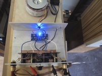
It is exactly as PD describes here http://www.diyaudio.com/forums/audio-sector/123003-commercial-gainclone-kit-building-instructions-5.html#post1516297 Here's a picture of my amp. You can see I followed his build exactly. Not represented in the photo, I'm using the snubberized version of the PSU.
Attachments
If it looks like this then something untoward is happening, possibly a stability issue/oscillation as there is no way that the GC output can shift in DC as the pot is turned 🙂
The input cap is mounted on the board where R1 goes. So there is no resistor being used. That is how PD specified in his build thread.
- Home
- Source & Line
- Analog Line Level
- Simple stereo gain stage