
check for oscillation.
If it is bad it will destroy your project.
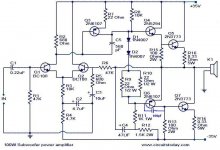
I don't see an output Zobel.
I don't see an input RF filter.
that increases the risk of oscillation.
What is the output offset?
Have you tested the amplifier into an open circuit and into a 8r0 resistor?
Have you shorted the input to signal ground for these tests?
C1 & C2 don't look right for a sub-bass amplifier. They might just about work as a high pass filter for a bass amplifier.
I would prefer to see a separate pre-amp to tailor the signal to suit the speakers.
That would then leave the amplifier to pass all bass frequencies it receives on to the speaker.
If it is bad it will destroy your project.
I don't see an output Zobel.
I don't see an input RF filter.
that increases the risk of oscillation.
What is the output offset?
Have you tested the amplifier into an open circuit and into a 8r0 resistor?
Have you shorted the input to signal ground for these tests?
C1 & C2 don't look right for a sub-bass amplifier. They might just about work as a high pass filter for a bass amplifier.
I would prefer to see a separate pre-amp to tailor the signal to suit the speakers.
That would then leave the amplifier to pass all bass frequencies it receives on to the speaker.
Last edited:
Dear sir
I am new to electronics could you please guide me
How can i change this to normal amplifier so that i can use this for keyboard
in the circuit diagram Q1 and Q2 are shown as bc108 but i have used mpsa42 and i am giving +/-45v supply
I am new to electronics could you please guide me
How can i change this to normal amplifier so that i can use this for keyboard
in the circuit diagram Q1 and Q2 are shown as bc108 but i have used mpsa42 and i am giving +/-45v supply
Last edited:
Dear sir
I am new to electronics could you please guide me
How can i change this to normal amplifier so that i can use this for keyboard
in the circuit diagram Q1 and Q2 are shown as bc108 but i have used mpsa42 and i am giving +/-45v supply
Here is one that will work with your mpsa42's and will be 10 times better that the one you posted. Runs on 40-0-40vdc. 🙂
OS
Attachments
As AndrewT said, it is probably oscillation.
The lower output, Q6, Q7, is in fact a CFB, Sziklai.
In this Quasi output stage.
My guess is that Q6-Q7 are oscillating.
I would try first with a capacitor (can be ceramic) 100pF
between B, Base, and C, Collector pins of transistor Q6.
If this does not help I would try with 220pF or 470pF.
The lower output, Q6, Q7, is in fact a CFB, Sziklai.
In this Quasi output stage.
My guess is that Q6-Q7 are oscillating.
I would try first with a capacitor (can be ceramic) 100pF
between B, Base, and C, Collector pins of transistor Q6.
If this does not help I would try with 220pF or 470pF.
Attachments
Last edited:
you need to verify the idle current of the amplifier ...that is measuring on the R14- and R16 the voltage drop ( carefully there you are looking at millivolts range )
if then this high means that your amplifier idles in higher bias than it supposed to be
the reason for that is the poor vbe multiplier that exists on this circuit ....
to make this in plain greek there is a string of diodes D1 and D2 that are supposed to be in perfect physical contact with the heat sink of your amplifier carefully now cause you need good physicaL contact but absolutelly no electrical contact
While your amplifier operate temperature goes up ( that is why you need a good heatsink ) together with the temperature also idle or biass goes up all the above drive your amp to a think called thermal run away .... to avoid this the D1-D2 while attached on the main heatsink will sense and monitor temperature and reduce bias to avoide thermal run away
of course the two transitors need insulation from heatsink and most imortand proper heatsink .... proper means a quiet big size ...
check all these and get back to us also post pictures of your work might also help
Hi,
what have you got connected to the output?
Those different voltages across Re indicate massively different currents.
Where is that difference in current going to?
Back down the NFB connection? Check the resistor you have fitted.
Check Re resistances.
what have you got connected to the output?
Those different voltages across Re indicate massively different currents.
Where is that difference in current going to?
Back down the NFB connection? Check the resistor you have fitted.
Check Re resistances.
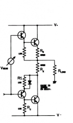
This not is the original configuration proposed by P.Baxandall.
You should change R14 for collector Q7 !
You should change R14 for collector Q7 !
Attachments
Last edited:
Raf,
no.
Both output transistors need the same value emitter resistor.
One can add a collector resistor to q7 but you must not remove the emitter resistor from q7.
no.
Both output transistors need the same value emitter resistor.
One can add a collector resistor to q7 but you must not remove the emitter resistor from q7.
Raf,
no.
Both output transistors need the same value emitter resistor.
One can add a collector resistor to q7 but you must not remove the emitter resistor from q7.
This output quasi complementary, one transistor is configured as a common collector (degeneration in the collector), while the other as a common emitter (degeneration in the emitter).
Not perfect, but it was available at the season these old TRs.
yes i connected 100watt 8ohms speaker
the sound is nice but the output transistors getting hot especially Q7 is getting hotter than Q5
remaining all are running cool
the sound is nice but the output transistors getting hot especially Q7 is getting hotter than Q5
remaining all are running cool
can i use this amplifier for music if i use one pair of 2n3773
does it sounds good please tell me
if any modifications required please let me know
thank you
does it sounds good please tell me
if any modifications required please let me know
thank you
no pictures , no comments on the D1 D2 issue , no information about the heat sink ... anything else i can do for you ???

sorry i forgot to attach picture
can i use this amplifier for music if i use one pair of 2n3773
Because you want to use these transistors 2n3773?
Because you want to use these transistors 2n3773?
one pair is enough to drive 100watt load
Sorry guys for this off topic reply. It is addressed solely to Lineup. Because he has disabled any contact information from his profile.
Hey, Lineup, we missed you.
How are you doing my friend? I am glad for your dynamic come-back, from which i can suppose that you are just fine.
Try a search in my last post in "Post your Solid state pics" thread, there is a photo and a reference of my last discrete OPA module. I would like to we discuss about it. And above all to learn your news. If you have the kindness, please post me a private message.
Fotios
- Home
- Amplifiers
- Solid State
- 100-watt sub woofer amplifier