My 1701A works fine except that in Distortion mode, the pointer will not settle completly. It will waver +/- 2 or 3 lines. After selecting a frequency and reading the distortion on the meter, if I press the 100 Hz or X10 or X100 switches, the set reacts as if a new frequency was selected. This is in the LOW DISTORTION mode. The FAST mode LED lights (as it would changing frequency), the meter pegs to the right (as it should) then the LED goes off and the pointer settles. It doesn't fully settle. There are times when the pointer swings to 2/3 of the scale then back. Pressing the above switches a few times returns the set to somewhat normal operation.
Anyone know of a good contact cleaner to use?
Anyone know of a good contact cleaner to use?
What you describe is correct behavior. When any change is made in the frequency or the switches are pressed it starts a timeout on the oscillator, part of the fast settling process.
How low does it go in self test 1 KHz 3V with the 400 and 30K filters on? If you get to .0015% you are near the performance limits. its possible to improve it from there but its a lot of work for a snall improvement.
ST warn's against cleaning the switches since the chemicals could cause leakage etc. I don't know what to say about a 20 year old switch array. If it was in LA you may need to. I would look at what Caig Labs DeoxIT® D-Series has that could be used.
Takes about 3 seconds to go back to LOW DISTORTION mode. Same as when it works properly.
I think I corrected the problem. The capacitors located on the Ratio switch or a bad ground connection most likely. Removed the top and bottom panel and the set works fine now.
I'll check and clean the ground connections.
Last resort would be to clean switches
I think I corrected the problem. The capacitors located on the Ratio switch or a bad ground connection most likely. Removed the top and bottom panel and the set works fine now.
I'll check and clean the ground connections.
Last resort would be to clean switches
Just to contribute here, I have 3 ST 1700's in my lab at the moment, 2 are Audio1's and one is my own. They ALL have problems developed over decades. The switches stop working properly, the null circuits stop nulling, etc. Still, they are OK units, better than most stuff out there.
I suspect the Sprague Tantalum caps on the RATIO switch as being the cause. Connecting my DMM for voltage test to the caps shows the following when the meter swings wildly.
Withe the DMM connected to - of the caps, the side leading to the ratio switch, the voltage rises slightly as the meter swings. It remains stable oyjerwise.
With the + side of the cap connected (this side is directly coupled to the output of the chip), voltage remains stable in either state.
Just a first look, but I may be on the right track.
Anyone knows where I can get those Sprague caps?
I don't have one handy to look at. Perhaps you can post a photo of the affected area. What options does it have?
The caps attached to the opamps at the output of the amplitude and phase null detectors are all large values. Are those what you are referring to? They are used for driving the photocells in the notch filters. They are used in integrating around the opamps that drive the leds connected to the photocells.
A good quality low leakage electrolytic would work OK. However I think you are looking at a symptom, not a cause. The network around the notch has the resistors from the tuning in it. An intermittent connection there would cause all kinds of grief. many of the connections in the box are using .025" square posts with push on berg connectors. These are quite reliable, for the first 10 years. Try remove/replace any around the switches to clean and renew the connections.
Do you have a scope to look at the unit?
Demian,
The caps are,
C313
C314
C315
C324
C325
C326
From 1 uF to 100 uF. 10%. 150 is printed on the cap.
I'll get some pic for you.
BTW. The distortion reading you asked about (post 2) is .001%.
All direct to the RATIO switches.
The caps are,
C313
C314
C315
C324
C325
C326
From 1 uF to 100 uF. 10%. 150 is printed on the cap.
I'll get some pic for you.
BTW. The distortion reading you asked about (post 2) is .001%.
All direct to the RATIO switches.
I don't have one handy to look at. Perhaps you can post a photo of the affected area. What options does it have?
The caps attached to the opamps at the output of the amplitude and phase null detectors are all large values. Are those what you are referring to? They are used for driving the photocells in the notch filters. They are used in integrating around the opamps that drive the leds connected to the photocells.
A good quality low leakage electrolytic would work OK. However I think you are looking at a symptom, not a cause. The network around the notch has the resistors from the tuning in it. An intermittent connection there would cause all kinds of grief. many of the connections in the box are using .025" square posts with push on berg connectors. These are quite reliable, for the first 10 years. Try remove/replace any around the switches to clean and renew the connections.
Do you have a scope to look at the unit?
Yes, I checked the oscillator output on the scope as well as frequency checks on my Fluke 1900A Counter. The pattern was excellent as well as the frequency on the 1900A. Rock solid over a few hour period.
The problem is either on the analyzer the switches or the caps.
Let me recap before further exploration-
1) Oscillator is stable (What happens to it when you press a button?)
2) Analyzer intermittantly jumps around but will settle to .001% or so.
Please confirm the following:
1) pressing a button on the frequency array that is already selected doesn't produce a massive transient on the oscillator.
2) The range switch causes the instability on the analyzer- Going down range sometimes causes fluctuations.
Places to check- first are the optocouplers. They are soldered in (unless on later units they used sockets). See if they are microphonic or connections around them are. They may need replacement, they do age a lot. Check that they are in the proper operating range, look at the current through the LED (voltage on series resistor) to see that its right and stable.
The rotary switch may have dirty contacts. Its silver plated and Deoxit should work well on it.
Do you have the IM option or any of the other options?
emian,
Demian,
To answer your questions.
Q1: When a preselected button is pressed (x10, 100 or x100 especially), the meter pegs in Distortion mode.
Q2: Never really settles and holds there. Always moving.
Q1A: Yes, produces 100% deflection of the meter in Distortion mode.
Q2A: Instability on all ranges that show a display.
I plan to view the output of the oscillator & analyzer sections on the scope over the weekend. I also plan to connect an ext oscillator to the 1701A and measure its distortion. This will indicate if the 1701A is reading the distortion of the 1701A oscillator or the problem is within the analyzer section.
Here's how to connect your 'scope to the 17xx;
From 17xx
Generator Out to Balanced Inputs.
Distortion Out to scope.
Monitor to scope.
I pulled and cleaned all Op Amps on both boards. Swaped like OP Amps to check if they were the issue. Also substituted a new NE5534H as a final check. Same results.
P.S. Mark and return OP Amps to original location.
When I first bought the 1701A (used) it arrived with little or no output from the oscillator as wll as a distorted pattern. Replaced U1 on the oscillator board. I had to by 10 pieces @ $8 each. Needless to say, I wasn't happy. On the up side, the oscillator now worked.
Cleaned INPUT, RATIO & ATTEN switches first with CRC then 100% Deoxit. ST warning relates to cleaners that were available 35 years ago.
I'll post my findings.
The 1701A has Option 003 (SET LEVEL).
Let me recap before further exploration-
1) Oscillator is stable (What happens to it when you press a button?)
2) Analyzer intermittantly jumps around but will settle to .001% or so.
Please confirm the following:
1) pressing a button on the frequency array that is already selected doesn't produce a massive transient on the oscillator.
2) The range switch causes the instability on the analyzer- Going down range sometimes causes fluctuations.
Places to check- first are the optocouplers. They are soldered in (unless on later units they used sockets). See if they are microphonic or connections around them are. They may need replacement, they do age a lot. Check that they are in the proper operating range, look at the current through the LED (voltage on series resistor) to see that its right and stable.
The rotary switch may have dirty contacts. Its silver plated and Deoxit should work well on it.
Do you have the IM option or any of the other options?
Demian,
To answer your questions.
Q1: When a preselected button is pressed (x10, 100 or x100 especially), the meter pegs in Distortion mode.
Q2: Never really settles and holds there. Always moving.
Q1A: Yes, produces 100% deflection of the meter in Distortion mode.
Q2A: Instability on all ranges that show a display.
I plan to view the output of the oscillator & analyzer sections on the scope over the weekend. I also plan to connect an ext oscillator to the 1701A and measure its distortion. This will indicate if the 1701A is reading the distortion of the 1701A oscillator or the problem is within the analyzer section.
Here's how to connect your 'scope to the 17xx;
From 17xx
Generator Out to Balanced Inputs.
Distortion Out to scope.
Monitor to scope.
I pulled and cleaned all Op Amps on both boards. Swaped like OP Amps to check if they were the issue. Also substituted a new NE5534H as a final check. Same results.
P.S. Mark and return OP Amps to original location.
When I first bought the 1701A (used) it arrived with little or no output from the oscillator as wll as a distorted pattern. Replaced U1 on the oscillator board. I had to by 10 pieces @ $8 each. Needless to say, I wasn't happy. On the up side, the oscillator now worked.
Cleaned INPUT, RATIO & ATTEN switches first with CRC then 100% Deoxit. ST warning relates to cleaners that were available 35 years ago.
I'll post my findings.
The 1701A has Option 003 (SET LEVEL).
Last edited:
Demian,
Here's a run down of Frequency settind as they relate to display on the 1701A meter in Distortion mode.
The set is less stable in LOW DISTORTION mode than in FAST MODE. There are times (not often) when the set switches by itself to FAST MODE
Setting DISPLAYED ON METER
10 X1: Pegs meter. High Notch indicator just begins to light.
10 x10: Unstable in LOW DISTORTION.
Pegs meter.
100 x1: Unstable in LOW DISTORTION
High distortion in FAST MODE
Pegs meter
100 x100: Stable (wavers a division or two) in FAST MODE
Unstable in LOW DISTORTION
100 X10: Unstable in FAST MODE & LOW DISTORTION
Last edited:
When it switches from fast to low distortion it engages the LDR. Those are the real weak point in the analyzer (aside from the many switches). I would source some replacements regardless. There are new ones from the UK that have lower distortion. I'm sure others here would want outplacements as well (like me). ST didn't reveal the actual part number. i figured it out years ago but have since lost track. The original vendor doesn't exist. Vactec does : Welcome | PerkinElmer so if we can figure out which part it was we can cross check- Silonex Inc.: Products: Audiohm Optocouplers . My schematic shows a CL614m note next to the part. That seems to lead to a black hole. I have a very foggy memory of 200 Ohms on resistance. The coupler has a 10K parallel resistance so that may be a real target value. I believe a VTL5C10 will work as a replacement so the Audiohm http://www.silonex.com/datasheets/specs/images/pdf/103465.pdf NSL-32B-101 might be a good replacement.
Another possibility -bad solder joints- the relays could have knocked them selves loose? Sound Technology 1710a Distortion Analyzer
Another possibility -bad solder joints- the relays could have knocked them selves loose? Sound Technology 1710a Distortion Analyzer
I don't mean to hijack this thread but..
...does anyone know how to contact Sound Technology? I tried sending them an email and left a phone message but no reply.
...does anyone know how to contact Sound Technology? I tried sending them an email and left a phone message but no reply.
When it switches from fast to low distortion it engages the LDR. Those are the real weak point in the analyzer (aside from the many switches). I would source some replacements regardless. There are new ones from the UK that have lower distortion. I'm sure others here would want outplacements as well (like me). ST didn't reveal the actual part number. i figured it out years ago but have since lost track. The original vendor doesn't exist. Vactec does : Welcome | PerkinElmer so if we can figure out which part it was we can cross check- Silonex Inc.: Products: Audiohm Optocouplers . My schematic shows a CL614m note next to the part. That seems to lead to a black hole. I have a very foggy memory of 200 Ohms on resistance. The coupler has a 10K parallel resistance so that may be a real target value. I believe a VTL5C10 will work as a replacement so the Audiohm http://www.silonex.com/datasheets/specs/images/pdf/103465.pdf NSL-32B-101 might be a good replacement.
Another possibility -bad solder joints- the relays could have knocked them selves loose? Sound Technology 1710a Distortion Analyzer
Thanks, Demian.
A reliable source adivsed me that the VTL9C would be a good choice. In fact, he had his 1701A out for repair and the LDR was replaced with the 9C along with a different resistor to compensate. Says that the set works fine. He uses it for his audio repair company.
...does anyone know how to contact Sound Technology? I tried sending them an email and left a phone message but no reply.
Same here. No reply.
It appears that the problem is solved. U206 is socketed, so I removed it from the board then reinserted it. Distortion is now reading .0008%. This is in test mode given in the manual.
INPUT: 3V
80K FILTER IN
RATIO: .01%
ATTEN: 0 dB
OUTPUT VENEER: Fully up
LOW DISTORTION MODE
Frequency: 1K (100 x 10)
The issue of the meter swinging wildly was caused by a dirty ADJ switch. I have Option 003 (AUTO SET). This switch is a sealed type where cleaning can't be done. Replacement is the only option. Cycling through it cleared it up for now.
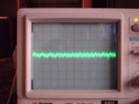
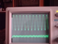
Here are a few pics of the set on my o'scope. The Distortion pattern (bottom trace in photo 1 and the trace in the pic on the right) is the same after removing U206 with the exception of the wild spikes.
Perhaps someone with a fully functioning set can post some pics of their output from the DISTORTION OUTPUT jack under the same conditions. In this way we can create a working file.
P.S. No, I don't have a pink scope.😀
INPUT: 3V
80K FILTER IN
RATIO: .01%
ATTEN: 0 dB
OUTPUT VENEER: Fully up
LOW DISTORTION MODE
Frequency: 1K (100 x 10)
The issue of the meter swinging wildly was caused by a dirty ADJ switch. I have Option 003 (AUTO SET). This switch is a sealed type where cleaning can't be done. Replacement is the only option. Cycling through it cleared it up for now.
Here are a few pics of the set on my o'scope. The Distortion pattern (bottom trace in photo 1 and the trace in the pic on the right) is the same after removing U206 with the exception of the wild spikes.
Perhaps someone with a fully functioning set can post some pics of their output from the DISTORTION OUTPUT jack under the same conditions. In this way we can create a working file.
P.S. No, I don't have a pink scope.😀
Attachments
Last edited:
Correction
Photo 1 is the DISTORTION OUTPUT trace only where as pic 2 is a trace of the 1K frequency from the INPUT MON (top trace) and the DISTORTION OUTPUT trace of the 1701A. (Bottom trace).
Photo 1 is the DISTORTION OUTPUT trace only where as pic 2 is a trace of the 1K frequency from the INPUT MON (top trace) and the DISTORTION OUTPUT trace of the 1701A. (Bottom trace).
It looks as though yours is more than meeting specs. getting replacement optocouplers is probably wise. Allied has the Silonex ones in stock in the US. They are supposed to have lower distortion.
The distortion waveform looks correct. if you enlarge it to one or two cycles of the fundamental you will see probably 3 cycles in the distortion residual along with noise.
John Curl upgraded his with AD797's which need adapters (they can be found) or you can get the LME49710 in cans that will plug in and probably work. Both have distortion fundamentals much lower than the parts in the box. Whether that will get better system performance may be limited by other parts of the design.
John Curl upgraded his with AD797's which need adapters (they can be found) or you can get the LME49710 in cans that will plug in and probably work. Both have distortion fundamentals much lower than the parts in the box. Whether that will get better system performance may be limited by other parts of the design.
Demian,
Thank you for your quick replys. I still want to buy optocouplers to have on hand. Would be nice to be able to plug in upgrades without circuit mods.
What this set really needs is to have all switches cleaned. The ADJ VR will be a problem since I can't open it to clean it. It can be opened, but the thin metal that holds the 2 halves together will not tollerate bending back and forth that is needed to open then close the halves.
- Status
- Not open for further replies.
- Home
- Design & Build
- Equipment & Tools
- Sound Technology ST 1701A Not Settling In Distortion Mode