Ok, this may be a clue. When you connect the amp to another ground source it buzzes as if you're touching the input slightly. A more raspy sound than with an iPod. A similar amp doesn't do this.
This has seriously stumped me this far 😡
You did not answer whether you have power line filters, or not. If don't, check for leaky primary in transformer to ground.
You did not answer whether you have power line filters, or not. If don't, check for leaky primary in transformer to ground.
I don't have any power line filters 🙂
I'll measure the transformer to ensure it's not doing anything silly. It's late again now so I'll do it tomorrow.
Do you have an osc scope? Also have you tried a swap on the rectifier tube (assuming it has one)? grasping a little at straws here but maybe one side isn't as viable.
Another check, along same lines with the PT or rectifier would be to check your input potential to ground potential both ac and dc.
Another check, along same lines with the PT or rectifier would be to check your input potential to ground potential both ac and dc.
Ground loop confirmed.
You coud have a look at: Earthing (Grounding) Your Hi-Fi - Tricks and Techniques
Solid state is concerned there though the problem is the same.
You coud have a look at: Earthing (Grounding) Your Hi-Fi - Tricks and Techniques
Solid state is concerned there though the problem is the same.
Possible steps:
1.
Insulate the input sockets from the chassis ground (i.e. if the sockets are bolted to the chassis, re-mount them and use an insulated mounting, hence separating the signal input ground from the chassis case ground).
2.
(As previously noted by waltube in posts #7 and #15) add a small resistor (5 to 10 Ohms) between audio ground and the mains chassis gound point, hence mildly disassociating the grounds. Bypass this small resistor with a small capacitor and anti-parallel diodes. See here: Power Supply for Power Amplifiers
3.
Ground the power transformer mounting leg / bolt.
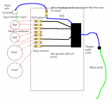
Post a sketch of the layout of the amp and the wiring, along with pictures.
Regards,
G.
1.
Insulate the input sockets from the chassis ground (i.e. if the sockets are bolted to the chassis, re-mount them and use an insulated mounting, hence separating the signal input ground from the chassis case ground).
2.
(As previously noted by waltube in posts #7 and #15) add a small resistor (5 to 10 Ohms) between audio ground and the mains chassis gound point, hence mildly disassociating the grounds. Bypass this small resistor with a small capacitor and anti-parallel diodes. See here: Power Supply for Power Amplifiers
3.
Ground the power transformer mounting leg / bolt.
Post a sketch of the layout of the amp and the wiring, along with pictures.
Regards,
G.
Possible steps:
1.
Insulate the input sockets from the chassis ground (i.e. if the sockets are bolted to the chassis, re-mount them and use an insulated mounting, hence separating the signal input ground from the chassis case ground).
2.
(As previously noted by waltube in posts #7 and #15) add a small resistor (5 to 10 Ohms) between audio ground and the mains chassis gound point, hence mildly disassociating the grounds. Bypass this small resistor with a small capacitor and anti-parallel diodes. See here: Power Supply for Power Amplifiers
3.
Ground the power transformer mounting leg / bolt.
Post a sketch of the layout of the amp and the wiring, along with pictures.
Regards,
G.
1. Nothing to do with ground loop through power outlet.
2. Illegal
3. Nothing to do with ground loop.
4. Layout of the amp has nothing to do with ground loops.
Remove that stupid 56r, and try to solder input jack's ground directly to ground wire near cathode of the 1'st tube.
It may help a bit.
It may help a bit.
Is the fact that the grid resistor has its own path to earth a bad factor in this by any chance?
Is the fact that the grid resistor has its own path to earth a bad factor in this by any chance?
This path is too short compared to resistance of the resistor, so actually it does not matter. I mean, connecting input socket's ground directly to cathode ground of the 1'st input tube may help a bit.
But the cardinal solution is (and I use it more and more often) to use a balancing transformer. I was running after vintage Peerless ones before, but recently tried Edcor's and found no difference.
But the cardinal solution is (and I use it more and more often) to use a balancing transformer.
At the input? Yes, it may work, but I think bigwill clearly wants to fix the underlying problem first, before resorting to very expensive 'last ditch' efforts. Get the amp quiet first, and then add the transformers!
bigwill, I've just read the thread and I've a feeling that the best solution involves the most work... strip it all out and wire it afresh!
The advice in post #29 may help: Power Supply for Power Amplifiers
(Mr Wavebourn says it is illegal, but I've definitely seen it in commercial equipment, and tweaking your own equipment is never illegal 😉 )
At the input? Yes, it may work, but I think bigwill clearly wants to fix the underlying problem first, )
The underlying problem is The Law. Requirement to comply UL regulations. Period. The amp itself is quiet, please read the discussion carefully
The underlying problem is The Law. Requirement to comply UL regulations. Period.
Hello Mr Wavebourn, in your land Bryston have sold thousands of amps with that system. Just go to their internet site and download their service circuit diagrams and you can see it. I used to own one. No issues. Period.
By the way, if a manufacturer wants to comply with UL guidelines then that has NOTHING to do with people tweaking their equipment at home, especially here in the UK. I can do anything I want to my amps. Period.
(By the way, you are talking as if you are a manufacturer?)
(By the way, you are talking as if you are a manufacturer?)
I am talking as if I got my MS EE degree back in 1981, as if I am an Engineer Designer and Technologist of Radio and Electronics Equipment according to my Diploma, and as if I know what I am talking about, and as if I follow the current discussion thoroughly trying to help to solve the problem.
Last edited:
I am talking as if I got my MS EE degree back in 1981, as if I am an Engineer Designer and Technologist of Radio and Electronics Equipment according to my Diploma,
And you turn everything into a competition of paper certificates? Good luck with that.
Never mind. Back to the fix...
I think my post #35 was reasonable. If bigwill really wants to fix it then it may be a case of striping it all out and doing it all again, optimising one step at a time.
Is the fact that the grid resistor has its own path to earth a bad factor in this by any chance?
It seems an easy thing to change... try it with the bottom of the grid resistor to the bottom of the cathode resistor.
And you turn everything into a competition of paper certificates?
Never. My equipment sound nice in real life, not on a paper. You may ask people who saw and heard my Pyramid-V amp prototype on BAF in San Francisco. 😉
There were miles of unshielded twisted pairs, from stage to stage, from room to room, from control rooms to studios, with line levels of signals. No hum, no ground loops, no RFI, despite of very powerful transmitters in the same building.
Guess, why?
- Status
- Not open for further replies.
- Home
- Amplifiers
- Tubes / Valves
- Quiet amp hums with signal source or input directly tied to star earth??