You could pull the PCB out and put all the components on the other side to make it easier to mod. Accept that it will be a mess for a while, but you don't want to have to pull 6 tubes and lift the PCB to change a couple of resistors or whatever to shift bias point or whatever mod you have in mind. Mine still hasn't got the bottom plate screwed on, it just sits on a couple of pieces of wood to allow airflow. Another thought I had, it would be a simple mod to change the paraphase inverter to a LTP differential type. Check the schem, not much would have to change. Coupling caps remain where they are, just change some resistors around from memory. Then use your ears to judge 🙂 You can always put it back when you get the card back.
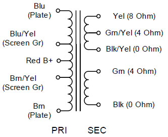
I just received my Hammond 1609 output transformers. I have a question on the hook-up. On the primary, there's two set of wires. I assume I have to connect only one. Is there any importance on the side I choose?
I just received my Hammond 1609 output transformers. I have a question on the hook-up. On the primary, there's two set of wires. I assume I have to connect only one. Is there any importance on the side I choose?
If you are just doing a straight replacement of the Meng OPTs, than don't use the UL taps (screen gr connections), just tape them up so they don't short out to anything (or each other).
Remember, phase is important with the OPTs, so make sure they are connected identically. Getting one reverse-wired has the same effect as reversing one of the speakers.
It would be interesting to see what this amp would sound like using the UL connections though. That requires removal of the screen resistors from the PCB, and connecting the UL taps to the screen pins of the appropriate tube socket.
I'm sure everyone here is interested in the improvement you hear (or not 😉 even with straight replacement.
Gary
Thank you Gary, I'll begin by connecting just the way it was, and if I'm successful, I'll take a few days to listen to it and then after I may consider using the UL connections.
Actually since the Meng yue uses GNFB it is more complex than just phasing of the speakers.
If you hook the plates up backwards, you will have positive global feedback and it will most likely oscillate (pretty much guaranteed).
The solution is as simple as swapping the leads to the plates.
If you hook the plates up backwards, you will have positive global feedback and it will most likely oscillate (pretty much guaranteed).
The solution is as simple as swapping the leads to the plates.
Just some extra info, may or may not help, who knows if our amps are wired the same? Just adds to the fun of it 🙂 On my amp, if I slide the sheathing back on the OPT wires I had white and green wires going to the tubes plates and red to the B+. The white wires from each OPT ran to the outside tubes, and the green wires ran to the inner pair of tubes. So with these new transformers the Blue wires would run to the outer tubes, and the Brown wires to the inner pairs. Or vice versa. My very bad guess is that the new Blue wires would go where the old green wires were, to the inner pair of tubes, but with these amps anything is possible, yours could be different, and I don't know for sure the phase relationship of the Hammonds. The negative feedback circuit will cause positive feedback if you get it back to front, which will cause instability. Murphy's law says you will get it back to front. To test, turn the amp on with speakers connected and some music already playing into it, keep your finger on the power switch, ready to switch it off. After the 20 second warmup time, if you start to hear any squealing/howling/unusual noise then switch off immediately and wire it up the other way.
Put some heatshrink over each Blu/Yel and Brn/Yel wire as they carry high voltages and a short to ground could kill the OPT, or do some other nasty damage. I you can, coil them up individually and leave them full length (as in don't cut them off short) in case you want to try ultralinear mode one day. If you ever try UL, you will need to cut the traces between the screen grids of each output pair (and remove the screen grid resistors as Gary said).
Be very interested to hear how it goes...
 Lets party! Who is buying drinks?
I'm just mulling over these two 812-A's, 6 807's, and 10 5B254M's I just picked up and wondering if I could shoehorn them into the Meng 😀
Should be able to light up a room with them....
Should be able to light up a room with them....
One thing you will have to be careful of in changing the OPTs is phasing of the fedback signal. If wrong, it is easy to correct by swapping the two transformer to plate connections at the tube sockets.
OK, I just finish install my new OPT and I think I experienced the feedback effect...very unpleasant. So...do I have to invert wires on both channels? Or only on one.
I just reverse both plate connections and I still get the feedback. Do I have to reverse just one?
If it is positive feedback you need to swap both plate connections (Blue and Brown wires). Hmmm. it is possible you have only one reversed and if you swap both you will still have one backwards.
Try pulling the output tubes out of one channel and listen to it. If the remaining channel is fine then just swap the leads to the channel that has no tubes. Insert the tubes and power it back up.
I would look at the output with no input with either a meter (ac) or scope. You should be able to measure the oscillation and see where the problem is.
When I had my OPT wired backwards, It was driving a square wave out ha very high frequency. I could measure the output with my DMM.
Last edited:
I invert just one and it works now. There was some cut wires on the orignal transfos, maybe it mistaken me...Here's a picture of what it was before I unplugged the originals....
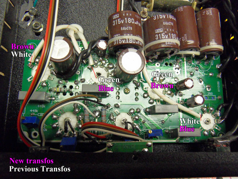
I invert just one and it works now. There was some cut wires on the orignal transfos, maybe it mistaken me...Here's a picture of what it was before I unplugged the originals....
Yes, you inverted one of the new trafo's.
Old White lead on one channel became new Blue, but old White on the other became Brown. Should have become Blue on both or Brown on both not one of each. I hope that made sense 😕
You should be OK now.
Not really easy to understand for somebody who starts like me....but I'm good at trying things out!
Put some heatshrink over each Blu/Yel and Brn/Yel wire as they carry high voltages and a short to ground could kill the OPT, or do some other nasty damage. I you can, coil them up individually and leave them full length (as in don't cut them off short) in case you want to try ultralinear mode one day. If you ever try UL, you will need to cut the traces between the screen grids of each output pair (and remove the screen grid resistors as Gary said).
Be very interested to hear how it goes...
I cut a little bit the wires...left enough to use them for UL. They are secured with heatshrink. I'll probably try the UL one day...and maybe not as far away. I'll ask you questions on how to do it when I'll be there.
Yes output power will drop, but so will distortion and output impedance.
I get 8W non-UL and about 6.6W UL mode with my amp.
I get 8W non-UL and about 6.6W UL mode with my amp.
The white wires from each OPT ran to the outside tubes, and the green wires ran to the inner pair of tubes. So with these new transformers the Blue wires would run to the outer tubes, and the Brown wires to the inner pairs. Or vice versa.
Ahh well, I tried to explain it...but it ain't easy...
Murphy's law says you will get it back to front.
Murphy struck in a manner I did not expect, as usual 🙂 Bird_dog you did well to get it sorted out.
Now, what we have been waiting for, is, how do the Hammonds sound compared to the originals? 😀
Hello,
did anyone measure the output transformers of a Meng Music Angel EL34 PP ( EL34B + 6N2 ) amplifier ? The raa is aproximate 8k Ohm.
I have removed the guts of my modified amplifier, rewired the input connector with shielded cable,mounted solid sockets and will rewire the whole amplifier.
Best regards,
George
- Status
- Not open for further replies.
- Home
- Amplifiers
- Tubes / Valves
- Meng Yue Mini schematic?