What about pentode with local feedback?
I built a tiny little amp using 6AU6's to drive 6AQ5's about two years ago. It did sound pretty good, but I never had the time to optimize it. It is still around somewhere, and I will get back to it sooner or later.
I have not tried any form of local or global feedback on this design yet. I built a 300B push pull amp with zero feedback about 6 years ago. It had a punchy dynamic sound that I haven't been able to match with any SE amp. The 300Beast as I called it, suffered a blown power supply cap about a year ago, and has sat quietly in the closet ever since. I have built a dozen or so SE amps since I built the 300Beast. I decided that it was time to build some P-P amps, and one of my criteria was to either rebuild the Beast, or make something better. So far I have been experimenting with triode mode zero feedback designs, and a differential driver circuit. This is how the beast was made, so I started there. I started to design the "universal driver board" that began with the Beast's driver schematic. Chrish asked about a driver for P-P 6L6GC's using 6SN7's. I looked down at that box in the closet that had about 25 6SN7's in it and said why not. The circuit used here is similar except for the tube choice.
I got a pair of large by huge by immense 400 watt Plitron toroidal OPT's from their surplus page a while back, so these are a useful possibility. I also have a pair of vintage UTC LS-57's that have been on the shelf for at least 10 years. Since the budget for new stuff is zero this year, I am going to build amps with the stuff that I already have. Well there are the OPT's for two amps, and I have at least 2 more sets of lesser quality P-P OPT's.
I plan to build one "big" amp of 50 to 150 WPC using the Plitron OPT's, one "small" amp using the UTC OPT's and maybe one or two more. I am in the process of mounting two driver boards, and two output tube boards to a piece of wood. This will be used to test different output tubes and OPT's using this driver board. I have all sorts of combinations to try, so I can't say where this will end yet. I want to experiment with a fully differential direct coupled amplifier, at least once. The probability for burnt parts is high there, so I will use cheap stuff for the first one. Remember, we still have some 6FW5's too.
Chrish asked about a driver for P-P 6L6GC's using 6SN7's. I looked down at that box in the closet that had about 25 6SN7's in it and said why not. The circuit used here is similar except for the tube choice.
I checked Ebay and sellers are selling adapters allowing loctal tubes to be used in octal circuits. I also noticed that prices of loctal tubes such as 7n7 and 7af7 are flying compared to a couple years ago.
Remember, we still have some 6FW5's too.
Indeed and I am itching to find a good project for them. I want to build a PP amp. I just haven't decided on Screen-drive or pentode. Probably the prior given your good results with that.
...7n7 and 7af7 are flying compared to a couple years ago.
Pssst. 14N7's
Pssst. 14N7's
True, as most people would not know how to switch filament voltage.
Chrish asked about a driver for P-P 6L6GC's using 6SN7's
For a starter circuit, look no further than the 1947-8 Brimar Radio Valve Manual!
The picture tells the tale, & may be summed up as:
6SN7 x2 + 5B/250A (807) x2 = 75W in AB2
The 5B/250A is an 807, which most of us would agree is functionally the same as a 6L6G (not even -GC, which is rated for more screen voltage and power handling). If 75W is enough for you (!) we should be able to build it exactly to their spec. (to begin with anyway - I'm not sure about the phase splitter).
The only curiosity is the -78V (14mA) bias. Klug. It it made up of about 25V for biasing the 807s, and ~50V across the 10K resistor loads of the cathode-follower driver, which also give efficient Long Tail Pair operation. ~5mA standing current in the 6SN7s keeps the gm reasonable, if moderate by the standard of later valves, let alone transistors - but you can clearly build a semiconductor-free AB2 if that's your preference.
The corresponding notes in the 807 pages of the book quote:
80W AB2 for 600V anode, 300V screen, idle current 30mA each. 6400 ohm A-A. 78V grid-grid peak input. 3% distortion, PROVIDED anode & screen voltage tolerance 0/-5% & grid bias 0/-3%.
Attachments
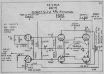
Instead of "Long Tail Pair operation", I should say "combination bias operation" in the above. The Follower 6SN7 has its grids biased positive (-39V) compared to the -78V common return point.
If you change anything around this driver 6SN7 (valve type, voltages resistors etc), the currents, follower biasing etc will need to be recalculated.
Also of note in the Brimar circuit is that no G1 nor G2 stopper resistors are used, but 47/1W parts are found in the anode leads. No doubt, for AB2 operation this will give the lowest distortion consistent with good stability, since grid or screen current draw will upset the bias conditions more than drops in anode voltage. It also obliges the constructor to take care with the wiring and minimize lead lengths & loop areas - or stability may be a problem. You may still end up with stability issues with othe 6L6 variants - perhaps increasing the 47Ohm value a little would be worth trying in this case.
Also of note in the Brimar circuit is that no G1 nor G2 stopper resistors are used, but 47/1W parts are found in the anode leads. No doubt, for AB2 operation this will give the lowest distortion consistent with good stability, since grid or screen current draw will upset the bias conditions more than drops in anode voltage. It also obliges the constructor to take care with the wiring and minimize lead lengths & loop areas - or stability may be a problem. You may still end up with stability issues with other 6L6 variants - perhaps increasing the 47Ohm value a little would be worth trying in this case.
I would also include active screen regulation. I think you will find screen stoppers will probably be necessary, since 807s like to Barkhausen oscillate on cut off. I would also replace the 47R plate stoppers with a stopper consisting of ten turns of #18 (AWG) wire, 7/16 in. inside diameter, space wound. Parallel with a 100R / 1W C-comp resistor conveniently mounted inside the coil. Mount that plate stopper right at the plate top cap connector.
I would also make the bias voltage at the 6SN7 grids variable so that the finals can more easily be brought into plate current balance. Better still, replace the 6SN7 cathode followers with MOSFET source followers. Source followers have way lower Zo than any cathode follower. That'll work much better.
I would also make the bias voltage at the 6SN7 grids variable so that the finals can more easily be brought into plate current balance. Better still, replace the 6SN7 cathode followers with MOSFET source followers. Source followers have way lower Zo than any cathode follower. That'll work much better.
I would agree with Miles observations. Then I would add to make the phase splitter a true differential pair, then I would look at that 4 to 10 volts drive requirement and say that another stage is needed for the amp to be useful. If I was going to add another stage, it would be another diff pair. My observations are that cascaded diff pairs seem to work better than anything else that I have tried even if it adds more glass to the design. So what I would get is diff pair directly coupled to a second diff pair, followed by a pair of mosfet followers to insure clean AB2 operation of any output tube.
Oh, wait that looks like the board that I am using. The last schematic that I posted was shown in post #277. There have been very few changes since then, because it works. It works really good to. I did see some really impressive power readings with 6L6GC's in pentode mode AB2. The 807 is really a 6L6GB with one significant difference The plate cap allows a much higher plate voltage than the octal bese. The power level seel with 6L6GC's is limited by the 500 volt maximim plate voltage rating. I have seen tubes and sockets flash over from pin 3 to pin 2, so I am not going to bend this rating.
I have decided that for my own personal amp I want to use triode mode without any feedback. I just like the sound. I get 70 watts out of a pair of KT88's in triode at 3% distortion without busting any specs, so that is good enough for me. I have seen over 100 watts in triode mode using 7403's with 75 watts at 1.8% distortion. The sound is really good too.
I plan on building an amp that is fully differential including the output stage. Obviously the power will not be as big since the diff pair output stage forces Class A operation. Excessive grid current will steal cathode current from one of the output tubes, so A2 must be limited to low currents.
I would agree with Miles observations. Then I would add to make the phase splitter a true differential pair, then I would look at that 4 to 10 volts drive requirement and say that another stage is needed for the amp to be useful. If I was going to add another stage, it would be another diff pair. My observations are that cascaded diff pairs seem to work better than anything else that I have tried even if it adds more glass to the design. So what I would get is diff pair directly coupled to a second diff pair, followed by a pair of mosfet followers to insure clean AB2 operation of any output tube.
Looks pretty much like we're working along the same lines here:
Schemo (Preliminary) Big Vix
George, was there a Eagle file for your driver board? I know your busy so don't sweat it if not.
Second question
What is that little bit with the lamp off to the side of the first 6SN7 on the Driver board?
What is that little bit with the lamp off to the side of the first 6SN7 on the Driver board?
George, was there a Eagle file for your driver board?
I am planning to sell at least one PC board based on this design in the future. It should be available sometime next year. For this reason I would rather not post the PC board files anywhere since I have already learned what will happen. I have posted the schematic, which I do with all of my designs. They can be built with PTP techniques. I have made some minor modifications to the design which are not reflected in the last schematic that I posted, but I will update it next time I get time to work on this project.
Tubelab Inc has never shown a profit, and would have dissapeared already if it wasn't for the Simple SE PC board. The funds from Simple SE and hopefully the Simple P-P board sales are what is financing the development of the new stuff like this driver board. There have been a few requests for this board, and I have already planned several amplifier projects based on them. As soon as funds are available I plan to get a small batch made.
About 25 years ago I was selling C band TV satellite receiver kits. Sales dropped off overnight because somehow someone else began selling exact copies of my design, cheaper. This was done in the days of tape and mylar layouts with the photographic duplication done by me. Their board had identical errors (crooked lines) that mine had. This could have only happened at the PC board house which was a small upstart that eventually failed. So did my company, DMA engineering.
No prob, just wondering, I was looking for something to try homebrewing boards with, I'll totally buy a few when you sell 'em. Really not trying to jump your S**t 😱
What is that little bit with the lamp off to the side of the first 6SN7 on the Driver board?
The neon lamp is used only if the negative supply is greater than -75 volts or so. When the board is first powered up the tubes are cold and non conducting. The CCS will attempt to feed 7 mA or so into a non emitting cathode causing the voltage to go to the negative supply rail. If the negative rail is greater than the HK rating of the tube, it could be damaged. The neon lamp is esentially open until its strike voltage is reached at which point it acts like a zener diode. I have used zener diodes in and TVS diodes in previous designs, but neon lamps are a sand free solution if the circuit design allows their use (65 volts and up strike voltage).
I'll totally buy a few when you sell 'em. Really not trying to jump your S**t
No problem. I am pretty free with my information, but I need to restate my position on PC boards every once in a while. My board designs involve considerable effort. I routinely get emails asking for, or offering to buy my board files. It would be a short while before I would be competing with my own designs, probably made in low cost offshore PC board houses.
Curious how this project is coming.
I know George is super busy, so I don't expect the board is nearing completion (although I'd love to obtain one).
I know George is super busy, so I don't expect the board is nearing completion (although I'd love to obtain one).
Chris has stated in another thread that he is about to resume construction of his amp. It was briefly discussed here:
http://www.diyaudio.com/forums/tubes-valves/158612-st-70-good-gets.html
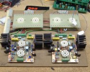
I got two prototype driver boards built and tested last August. I decided that I really wanted to build a stereo test amp so that I could listen to several output tube / OPT combinations so that I could decide what kind of amps that I want to build in the end. I got the breadboard shown below assembled so that I could do some testing, but it has not been powered up yet.
I put everything else on hold when the Simple P-P boards arrived since I had to finish up the manual for it. I can't even begin to list the things that have gone wrong since then, but I can see the light at the end of that tunnel, and have reasonable confidence that it is not an oncoming train. During this time I have collected a big bunch of tubes and transformers to test from 45's to some big sweep tubes, and maybe even some 813's. As soon as the Simple P-P manual is done, I plan to return to this project.
http://www.diyaudio.com/forums/tubes-valves/158612-st-70-good-gets.html
I got two prototype driver boards built and tested last August. I decided that I really wanted to build a stereo test amp so that I could listen to several output tube / OPT combinations so that I could decide what kind of amps that I want to build in the end. I got the breadboard shown below assembled so that I could do some testing, but it has not been powered up yet.
I put everything else on hold when the Simple P-P boards arrived since I had to finish up the manual for it. I can't even begin to list the things that have gone wrong since then, but I can see the light at the end of that tunnel, and have reasonable confidence that it is not an oncoming train. During this time I have collected a big bunch of tubes and transformers to test from 45's to some big sweep tubes, and maybe even some 813's. As soon as the Simple P-P manual is done, I plan to return to this project.
Attachments
Well, after stating I was about to start construction.....
I was sitting down to the components of the power supply, looking over schematics - even found an error I need to fix - the phone rang... The people I rent my apartment from want to move back in in a couple of weeks! Looking to find a new place now, with a garage so I have a good place to work! Expect things to be on hold for a few weeks, but I am committed to building this thing! I will post when I begin.
Cheers,
Chris
- Status
- Not open for further replies.
- Home
- Amplifiers
- Tubes / Valves
- 6L6GC AB2 Amp