Hi all,
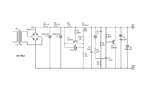
I have a schematic of a PSU for the B1 buffer from a B1 tread, though I can't remember by who and when. Please see image 'psu'. I have done the pcb based on the schematic. Please see pdf 'B1 psu pcb'. Now, my transformer is 230Va 28v (it was stated as 24v but the output is 28v) but my out-put is only 13.5v. And when I put in a 230Va-32v transformer, my out-put is only 15.5v. What is the problem and how do I solve it? Can the B1 buffer be driven by 13.5 or 15.5v? I read in the article by NP that 18v-24v is needed. Thanks in advance.
pmchoong
Attachments
Hook up a at the psu output a 1W resistor in the range 470R to 1K. Then measure the voltage drop across R3 and the voltage between R2 and R3 referenced to ground. Come back with those values.
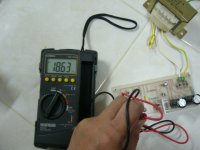
I have a 1/2w 470R resistor at the output. I can't find 1w R470 but I have 1w 62k. After putting in the 1/2w 470R, voltage across R3 is 2.75v. Voltage between R3 and Gnd is 18.27v. Voltage between R2 and Gnd is 23.56v. Output is 14.7v. Voltage output before the 1/2w 470R is put in is 15.30v and not 13.5v as mentioned above. The transformer used is a 230V - 28v-0. When I use transformer with a 32v-0 out, the voltage is only 16.5v (without the 1/2w 470R in place).
Last edited:
Hi
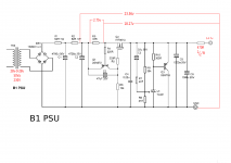
I have attached a drawing of the measurement. Am I doing something wrong here?http://www.diyaudio.com/forums/images/icons/icon5.gif
I have attached a drawing of the measurement. Am I doing something wrong here?http://www.diyaudio.com/forums/images/icons/icon5.gif
Attachments
check Q1. Is it the right way round?
It should have ~600mV across BE and that forces ~600mV across R3. 2.75V is seriously wrong.
What is the voltage drop across R1 and across R2?
What is the load across the output?
I hope you are using just one secondary (24Vac) to power onse side of the supply.
The 33r is setting the pass current of the CCS. this should be ~ 600mV/33r ~18mA.
This is a bit low to supply a B1 and too low to supply two channels of B1.
The 470r resistor. Is it onnected to ground to simulate a load? That will draw ~31mA @ 14.7v and run very hot dissipating ~460mW.
Hang on a minute.
23.xVolts -18.x volts is not 2.75Volts.
You are not measuring correctly.
Start again.
Last edited:
1) Q1's BE is measured at 2.74v.
2) Voltage across R1 and R2 = 0.9mV.
3) load across the output = 14.7V
4) Yes, one secondary (28v) and one 0
5) 33r?
6) Yes, the 470R is connected to a piece of metal on the ground
7) R3 referenced to Gnd = 18.35v
8) R2 referenced to Gnd = 23.54v
9) in your opinion, where or which part did I measure wrongly?😕
10) the pcb layout is attached as pdf file in post#1 above, and I have checked again on the board, the Q1 is soldered on correctly
Thanks
Last edited:
what is the point?
I tell you what does not add up and still you repeat the same wrong measurements.
I tell you what does not add up and still you repeat the same wrong measurements.
Hi Andrew, sorry, I was measuring in DC. I have very limited knowledge on electronics.
1) Q1's BE is measured at ~0.006v
2) Voltage across R1 and R2 = ~0.006v
3) load across the output = 14.7V
7) R3 referenced to Gnd = 18.35v
8) R2 referenced to Gnd = 23.54v
Thank you again. I will check back tomorow. Thank you very much for helping.
1) Q1's BE is measured at ~0.006v
2) Voltage across R1 and R2 = ~0.006v
3) load across the output = 14.7V
7) R3 referenced to Gnd = 18.35v
8) R2 referenced to Gnd = 23.54v
Thank you again. I will check back tomorow. Thank you very much for helping.
2.) 0.006V tells us the current passing into the reg circuit.
I = V/R = 0.006/62r = ~0.1mA.
The regulator is effectively turned off.
1.) 0.006V across BE of Q1 tells us that the regulator CCS is effectively turned off.
8.) - 7.) 23.54 - 18.35 = 5.19V where did 2.75V come from?
Is the 470r connected from the reg output to the reg return?
I = V/R = 0.006/62r = ~0.1mA.
The regulator is effectively turned off.
1.) 0.006V across BE of Q1 tells us that the regulator CCS is effectively turned off.
8.) - 7.) 23.54 - 18.35 = 5.19V where did 2.75V come from?
Is the 470r connected from the reg output to the reg return?
2.75V across R3 tells us that the total current drawn from the power supply is 2.75/33 = 83.3mA. Since the load should draw 14.7/470 = 31.3mA, it means that roughly the difference most likely goes through the shunt transistor, Q3 (2sb716).
I see two problems. First, if you really want 24V out, then make sure the transformer + filter and a load connected to it (100mA to be sure) gives you about 32-34V out. The series mosfet Q2 needs to drop some voltage to give you regulation. Right there's too much voltage drop across R1, R2, and R3 and there's nothing left for regulator to work with. If you can't get a higher voltage transformer right now, do this. Take R1 and R2 out. With a good regulator you don't even need them. You can replace them with some very small value resistor, if you really want to, something like 5R.
While testing the regulator, I strongly suggest you to replace your reference U1 (tl431) with a simple zener diode (two 12V, or two 10V even better, in series). Then you don't second guess the reference.
HTH
no.2.75V across R3 tells us that the total current drawn from the power supply is 2.75/33 = 83.3mA.
it tells us that Q1 is not working.
Besides that 2.75V does not tally with the other two voltages referenced to ground.
The measurements are ****.
Last edited by a moderator:
no.
it tells us that Q1 is not working.
Besides that 2.75V does not tally with the other two voltages referenced to ground.
Yes Andrew, I noticed the measurement discrepancy, but was still trying to give him an indication how things should behave. I guess I should have said, ASSUMING that the 2.75V and 14.7V are measured correctly. I certainly hope that the 470R load is connected as a load, i.e. one leg to reg output, one leg to GND.
C5 and C6 don't need to be there. One 100-220uF cap is plenty.
 Andrew, no f-bombs allowed here, you know better!
I have changed the Q1(2sa872). Now I have a :
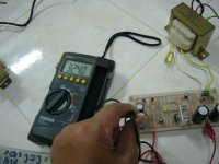
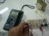
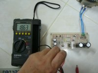
a)18.63v output (Please see image 'output').
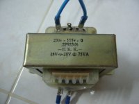
b)This is with a 24v-0 transformer (image transformer 1).
c)R3 referenced to GND = 31.05v (img 'R3 reference to Gnd)
d)R2 referenced to GND = 32.40v (img 'R2reference to Gnd)
e) voltage across R3 = 0.646v (measure across R3)
But when I changed to a bigger transformer (28v-0-28, which have an output of 32v), I still get a 18.63v output.
a)18.63v output (Please see image 'output').
b)This is with a 24v-0 transformer (image transformer 1).
c)R3 referenced to GND = 31.05v (img 'R3 reference to Gnd)
d)R2 referenced to GND = 32.40v (img 'R2reference to Gnd)
e) voltage across R3 = 0.646v (measure across R3)
But when I changed to a bigger transformer (28v-0-28, which have an output of 32v), I still get a 18.63v output.
Attachments
Last edited:
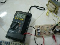
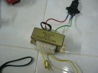
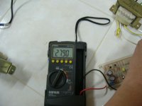
The 24v-0-24v transformer output is ~27.90v (image 'Transformer output'). The bigger transformer is 28-0 which has an output of ~32.80V (img 'tranny2'). The output with the bigger transformer is 18.63v (img 'output with tranny2'). Why? I thought a bigger transformer should give me a higher output? Thanks for the help.
Attachments
Last edited:
that looks like a 24V centertapped transformer to me... not a 24-0-24... I would think that the AC voltage you are getting is closer to 12V (unregulated) than 24V with the way you have it wired up... but I've had a few drinks tonight so feel free to ignore me 🙂
Tony.
Tony.
that looks like a 24V centertapped transformer to me... not a 24-0-24... I would think that the AC voltage you are getting is closer to 12V (unregulated) than 24V with the way you have it wired up... but I've had a few drinks tonight so feel free to ignore me 🙂
Tony.
Should I wired both the 24v wires together?
Should I wired both the 24v wires together?
Don't.
Dude, when somebody takes the time to think about your problem and then takes the time to give you suggestions, and you ignore them, what's the chance you get help again?
Dude, when somebody takes the time to think about your problem and then takes the time to give you suggestions, and you ignore them, what's the chance you get help again?
Hi ikoflexer,
I appreciate your time and help. I read from Andrew in post #11 above that Q1 is not working, so this is the quickest fix that I go after. It seems to work but I know there's still some problems. I will change R1 and R2 to 5R as you suggested. Also the caps and TL 431. Thanks
- Status
- Not open for further replies.
- Home
- Amplifiers
- Pass Labs
- Help with B1 PSU