Instead of Neodymiums with health warnings like "will break fingers",
and assembly procedures described "might swing around explosively"
Have you guys considered a simple field coil???
and assembly procedures described "might swing around explosively"
Have you guys considered a simple field coil???
Well I wish I had joined this excellent forum before almost breaking my fingers putting this thing together!?
How much current would be needed to get the same kind of output? More generally could a short electromagnet be trial-built that would, say be almost impossible to get off the front of a refrigerator when energized?
How much current would be needed to get the same kind of output? More generally could a short electromagnet be trial-built that would, say be almost impossible to get off the front of a refrigerator when energized?
Maglock Strong
As a matter of fact, I work at an airport, we have them all over!
Do maglocks use DC? If so, how many volts? (I'm thinking power supply)
As a matter of fact, I work at an airport, we have them all over!
Do maglocks use DC? If so, how many volts? (I'm thinking power supply)
I just asked our technician here at the airport, and he told me maglocks typically use 24VDC. Probably too noisy to use the power supply, but that could be constructed. One or two of those...
Its a cool idea - I wonder if there would be an even flux density through the diaphragm area, and if not, what effect that would have. I guess the next question is what current, resistance and wire gauge. It should be pretty easy to setup...
I think you might want a moderately high impedance current source?
Remember that any field coil might also act like a secondary winding.
I'm not sure how well leakage inductance moderates that effect???
Voltage protect (transorbs or crowbar) to handle any sudden collapse
or short across the magnetic gap... We still speak of crushing forces!
Just forces with an on/off switch.
I'm no expert on field coils, totally blind leading the blind here.
Maybe missing something critical? Definitely seek a second opinion
from someone who's actually done it before building anything field
coil supply-wise for audio. I am not that person.
Last edited:
Flux Consistency
Cuibono -
Uniformity of flux over time might be a deal-breaker if a huge delta in current spikes through the coil. Maybe we could get an EE to opine on this?
As for consistency over the plane of the diaphragm, that's no problem. These AMT's are very tolerant of imprecision. The Neo magnet I used is a bit stronger on one area of the flat pole surface, and this does not seem to have affected the sound. Even the ESS models had a good deal of manufacturing variance.
Maybe you also want one big shorted turn on the pole? That would effect only AC fluxes,
and not the DC flux that is present continuously... Sorta like JBL has a shorting ring???
I'm not sure shorting a turn, thats any diff than a low impedance style voltage supply???
But I'm pretty sure we don't want said power supply to look like 8 ohms, seen through
a transformer. Else your amp is gonna work into that load maybe instead of the parts
that should be moving.
Somebody has done this voice coil thing before. Its gotta be documented somewhere...
Why am I not finding it? Other than my Hammond organ...
kenpeter, I had a different picture in my head (if I understand you) - I had thought we could wrap the edge of the diaphragm in wire, then run dc through it to create a magnetic field through the diaphragm - basically an 'active' tweeter. Of course, the diaphragm's wires would be connected to an amp as usual.
Calling e-mag experts!
Now I think I see what you are saying - round cross-section wires are better than angled metal pole pieces in front of the diaphragm, and they could go closer in to shift the diffraction upwards in frequency. Everything else at the front of the speaker would be flush like a dome, even including a felt ring, I mean rectangle.
So, if I understand the questions, would it be possible to flow flux perpendicular to the plane of the AMT diaphragm using power, taking care with the electronics to power-up up nicely, and having only a coil section coming around the front?
I wonder if there is an authority on electromagnetics at diyAudio who could stop in and elucidate the forces. Mr. Emag Expert, are you out there?
Wires in front of diaphram??? Like a fan grill, If thats what you are suggesting???
I think you will still need pole pieces to concentrate flux. Any coils are gonna be way
too dense (and needing physical support, the field pushes them too) to blow through.
I think you will still need pole pieces to concentrate flux. Any coils are gonna be way
too dense (and needing physical support, the field pushes them too) to blow through.
http://www.magneticlocks.net/
Reality check prices, voltage, current, and holding pounds in a variety of shapes...
Their wall wart supply don't look all that exotic. Maybe nothing fancy is needed?
As for shorted turn, unless they lamm the thing like a transformer, its already
probably "shorted". I guess lets hope thats a feature and not a problem... ???
The assemblies you built before (and most loudspeakers in general) aren't
lammed to prevent, nor ringed to enhance eddy currents, so there's a good
chance that isn't critical.
Last edited:
Plug 'n Play Magnets
Neato, check out this model in magneticlocks.net:
http://www.magneticlocks.net/proddetail.asp?prod=MAG1300GF&cat=12
It's only $100. Looks like the center strip is one pole, and the outsides are the other. The whole thing is only a couple inches wide, though...
Ah-hah, look at this one:
http://www.magneticlocks.net/proddetail.asp?prod=FAS-CE1625LSWR&cat=14
It's the model MAG-CE1625LSWR. This thing looks like it was made for an AMT! With this I would use band iron, alternating glued pieces of open/crosspiece/open/crosspiece, for the external pole. Neil did a few variations using band iron in his Audio Amateur article. This way it could be cut, stacked and ground flat so its back matches the width of the outer magnet strips on the lock exactly. Inner pole piece of course comes forward from that center strip to meet the AMT diaphragm. And we sing from our diaphragms, not from our domes.
- And you must be right, how critical could power be if it uses an on-wall supply? Could use a regulated 24VDC supply. You could get everything fitted nicely, then step up the voltage gradually. And a resistive crowbar delay for on and off.
This would be extremely cool if one of us tried this. 😎 Don't look at me, I have to finish my center-channel project and I can't shell out $250 US per driver! Maybe someone could salvage a pair off the gates of a forclosed mansion?
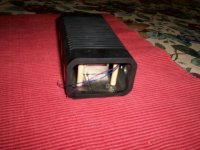
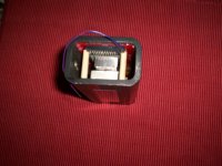
Fastening the Diaphragm
Before in this thread I mentioned one corner of the diaphragm came unstuck, this despite choosing the extra-sticky 3M tape with some care. I seems the warpage works on the adhesive over time and slowly pulls it apart. 😡
1/4 inch dowell to the rescue - I carved a notch on the diaphragm side and ground the other until it fit with enough extra length to prop up the side ends, almost to the corners, gently but firmly against the sticky tape bezel. A half-drop of silicone adhesive on each end keeps it situated.
It probably came apart from vibration - - this driver went loud when I tested it. Glad I didn't seal it up right away. Adhesive just isn't enough for the ESS stock replacement. Also my first listening impressions and tests above are with a corner of the diaphragm flapping in the breeze.
Next time (if ever there is a next time), I'll tap in 4 holes in the front of the outer pole during the carving and grinding and hold it on with 4 nylon screws and clips. Maybe 4 notches and a long clamped thingo down each side holding the diaphragm snug against a sticky gasket.
Tape alone is not enough.
Attachments
I can't access the website at all?
I'm may try this sometime, but I'd love to see some measurements of what you can get with your ATM - particularly, how low it can be crossed, and how loud it can play. Thanks for sharing this project!
Another Magnet Source
WonderMagnet ran out of the NIB magnet size and orientation I used, but here is another source:
products_id_52 | N50 Neodymium Magnets, 2 in x 1 in x 1/2 in Rare Earth Magnets for Wind Turbine - Applied Magnets & WindMax Wind Turbines
This one also is intended for generators and motors. Search terms used are "magnetized through the thickness" and "poles are on the largest area."
Has it been 5 weeks? Gotta get these in a box an see what we've got...
I Need a Box...
People, where can I get a speaker box for this project? My tool shed is a mess, and I'm busy getting my gear into a cabinet. To get this thing unstuck I need to just buy a cabinet and stuff these drivers into it.
Thanks!
People, where can I get a speaker box for this project? My tool shed is a mess, and I'm busy getting my gear into a cabinet. To get this thing unstuck I need to just buy a cabinet and stuff these drivers into it.
Thanks!
I Don't Need a Box
Boxes sound boxy, unless you do everything to prevent that. On second thought, I'll mount the drivers on a baffle. The Heil and the BG mids will be dipole, and the woofers will be 1/4 wave TLs made out of PVC pipe. I can try curtains to soak up the back wave.
Right now these are just another set of drivers. Going over to the multi-way speaker section to lurk for ideas.
It's been a blast. But I hafta get this project done before doing anything else atypical. See you later!
- Status
- Not open for further replies.
- Home
- Loudspeakers
- Planars & Exotics
- The Neil Davis Heil AMT