scott wurcer said:Typical strategy would be to buy a working model and improve all you want.
Agreed, if a working model is available. By making your own when one is available, the manufacturer could legitimately claim that you have denied them the revenue they are entitled to. But if no product is available?
Sheldon


"Hi Marek,
I am in the process of building/designing a magnetic suspension tone arm and have several email contacts with Frank Schr�der. NICE GUY! Very helpful! As you may have discovered there are some things he just hints at and which could be a bit questionable. I have a few posts on line on the subject and have included a link to an interim design I am using pending my final design. See: www.apricot.com/~bgruhn/turntable/magarms.html
I have been unable to access the link with your arm photos. Could you please direct me to them?
In the various discussions on DIY Schr�der tonearms I find certain terms to be rather loosely or poorly defined. WOBBLYNESS being one of them. You state that you "fixed" that by sharpening the magnets. Are these Wobbles the same as the tendency for the arm to rotate axially along the long axis of the arm? So far I have not been able to change this by shaping magnet pole pieces. The only thing that works for me is to raise the attachment point of the string (single string model only) to somewhere in the center of the tone arm wand rather than at the underside of the upper magnet. Now doing this stops the floppiness. from here on, if there is still some jitteriness, it could well be fixed with polepiece shaping (sharpening). I one of Frank's postings, or was it an email to me?, he mentions that the string attachment point is an important parameter (my word). Also note that no photo of a real Schr�der arm shows any hint of radical shaping of the magnet faces. So it would
make me development process easier to know if the rotational floppiness is one thing, and the wobbles is another. I "suspect" that where Frank positions the attachment point of the string is the real SECRET of his.
To sort of test my theory I took an early test arm- wand, drilled a small hole from one side of the tube through the other side on the horizontal axis of the tube. There was another hole in the top wall of the arm tube for the string to go through. This hole was a good size clearance hole for the string. Then I tied a very small loop in the string, passed it down into the arm tube and pushed a pin through the tube and the string (thread actually). Then I anchored the string to the upper support bracket. This made for a very stable configuration.
Another minor problem is that I don't know how to define where the pivot points actually are.
So there you have it for an introduction. Please get back to me, and hopefully we can have some dialog on the subject. In deference to Frank's wishes I think we should keep these discussions on a private email basis.
Thanks, and hoping to hear from you soon,
Bill"
Hi Bill,
I wish to keep the discussion public.
Read my posts (skip the legal BS which has nothing to do with my DIY project) and ask any question.
Marek
Hi Marek,
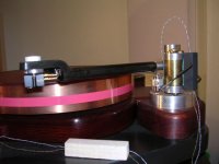
Thanks for posting the new pics. That arm is quite a tour-de-force. Well done. Sorry for not responding with thanks sooner, but I've been caught up in activity for several weeks and just haven't done it. Cutting the grass every other day or so is part of the problem. I have had some little time to work on the next generation of the bearing using the single thread design and progress is being made.
I note that your counterweight is made in two pieces with small cylindrical projections on the bottom at about 4 and 8 o'clock respectively. Are they intended to provide some additional stabilization of the axial flopping tendency of low thread attachment points as well as providing a good way of setting azimuth?
Bill
Hi Bill,
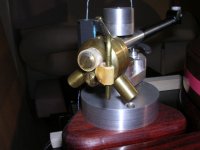
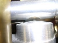
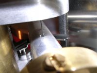
Yes and yes, the cylinders turn in and out for fine adjustment of azimuth. The screw in the end of the shaft is a plug to keep fluid in. (the aluminum shaft has a chamber filled with oil and lead powder). The fourth screw is for fine tuning of VTF. The rubber bands hold tiny magnets for anti skating force at beginning of LP.
Next picture shows shape of the magnets.
Attachments
Hi Marek,
Do you feel any need for additional tonearm damping, by counterweight decoupling perhaps? No hints of arm resonance at low frequencies? I'm asking because I'm still not fully satisfied with my Ladegaard arm in this regard, which has a common feature with the Schroeder design, namely it is about fully decoupled from the tonearm base. I dunno what kind of music you prefer, but this phenomena is rather pronounced during full symphony orchesrta crescendos. It has nothing to do with tracking: my arm tracks "tortue track #3" on test record with flying colors! Looks like wood by itself (cocobolo oil impregnated in my case) does not provide sufficient damping for high-energy stylus vibrations, which are stored in the arm and bounced back to the cart with phase shift, smearing the sound.
Michael
Hi Michael,
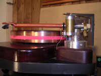
The aluminum part of my wand (where counterweigh is located) is hollow and filled with damping fluid, the other side (where wood wand is pushed in) has a bit of damping paste.
I believe that string (with couple kG of tension) conducts some vibrations out and magnetic field absorbs rest of it (changing it into heat)
Marek
Attachments
I don't want to get too corny or anything, but it is threads like this that make me proud to be a member of this forum. BrVO Marek!!
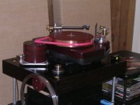
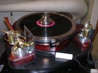
Is the platter on the TT mag suspended also?
Is the platter on the TT mag suspended also?
Thanks Dave…
"Is the platter on the TT mag suspended also?"
No, it is not. I don't need mag suspension under platter or TT because my floor is heavy concrete slab. Also I don't tolerate strong magnetic field near cartridges. You may like to read this:
http://www.diyaudio.com/forums/showthread.php?s=&threadid=100916&highlight=platter
I will upload pictures to that thread, just ask over there.
Marek
Attachments
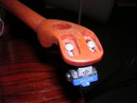
Explanation to picture in post # 50 - both magnets have conically shaped ends with slopes close to 7 degrees. Additionally the magnet in the wand is filed on sides to follow the cylindrical profile of the wand.
Further description of my tonearm with wand hanging from a thread (not the mutant):
There is a hole at the bottom of the magnet to accommodate the knot. The string goes up through a narrow hole of 1/32" in diameter, the same as the diameter of the string. Then the hole widens, so the string does not touch the wall any more. Therefore the true attachment point is where the string is free to bend.
The bearing is not a unipivot though it has a pivot point. The wand hangs from the string, but from mechanical point of view it is held in space by two forces - the string pulls up and magnets pull down. The first force is attached where the string becomes free to bend. To simplify discussion we can assume that the second force is attached at the gap between the magnets.
These two attachment points are not rigid, they move slightly when additional forces are introduced (when the headshell is forced up and down or the wand is twisted, pushed or pulled). The closer these two points are, the more freely the headshell moves up and dawn. At the same time the wand becomes more free to twist - as a consequence the magnets grab each other on the side. In my tonearms these two points are close to each other - the headshell moves up and dawn freely, almost like in a unipivot without the unipivot wobbliness. To keep the wand from flipping sideways I shaped the magnets in such a way that the gap widens going away from center and it widens more on sides than on front or back. To keep the headshell horizontal I used counterweigh with low center of gravity. If you move the string attachment point up, the tonearm will become more stabile but will require noticeable force to move the cart up and dawn which is no good. The secret is to chose the attachment point in such a way that tonearm is stabilized a bit, but is not stiff. I did not experiment that much and certainly not enough to be entitled to say where the most optimal location of that point is or what is the best shape of the magnets. All I can say is that I am totally satisfied with the way my tonearms work.
It is possible to calculate optimal geometry of the bearing - I did these kind of exercises in college 35 years ego - believe me it is better to stay away from it. To show what is going on in vertical plane, tangent to the long axis of the arm I made a simple model - see attached picture. Short, stiff rubber bend represents the magnetic force. Try two different hookup points. Move the end of the arm up and down - you will see the attachment points moving, you will feel that stiffness of the arm is different with different hookup points. You will be able to locate the pivot point - watch closely and you'll be able to see it, that spot does not move.
Attachments
I am little bit confused....
Hi,
In your design, are the magnets attracting each other or are they repelling each other ?
Regards,
Bins.
Hi,
In your design, are the magnets attracting each other or are they repelling each other ?
Regards,
Bins.
reply to post #56
Hi Marek,
Thanks for your post #56 and the images you have posted as well. My tonearm is progressing very well and I am able to evaluate each modification by listening to records for several days after each one. It has been clear to me for a while now that the choice of the thread attachment point is critical to successful implementation of the magnetic bearing. You mentioned that you provided a small hole in the top side of the arm tube magnet for the string effectively making this surface the attachment point. I have chosen a different approach which makes the choice of attachment point position somewhat easier to make. First I make a small, ~.032" diameter hole all the way through the aluminum part/tube where the magnet will be mounted. This gives vertical alignment of the thread with the center of the magnet. Then I bore out the hole the magnet is mounted in. Then I overbore the top hole to take a tapered post with the thread hole bored into it. The length of this post is chosen to place the attachment point (where the knot in the thread rests) at the desired position. The post is then swagged into the armtube. The position I am using now is just a few thousandths of an inch above the center line of the arm tube. Next I bore out the post to almost the bottom of the post. This provides clearance for the arm to move up and down without touching the thread and also makes a little well, which Frank Schroeder speaks of, to take a small amount of silicone damping fluid. The counterweight stub is bored out all the way through to the area where the magnet and post are. Now I feed the thread down from the top of the post to as far as it will go. Then with a wire hook or a jewelers saw blade I fish the thread out through the cw stub. So now we have a cat who ate the string but it comes out both ends. Tie a good substantial knot in the thread and pull it out the top side till the knot rests against the bottom of the post. clip the thread off at the back side of the stub so there will be something to grab to remove the thread if replacement is needed. I use a press fit for the magnet which has a (for now) flat face. The lower magnet has a dome shaped pole piece. Note that this design makes drilling the magnet unnecessary even though quite easy to do. I got some Kevlar thread at the fly tying department of a BassPro shop. I think this will be the thread to use. Works well so far. This post is long enough for tonight. More to come along with some photos.
Bill
- Status
- Not open for further replies.
- Home
- Source & Line
- Analogue Source
- Magnetically suspended DIY tonearm