Welcome back, Alan-1-b, it's great to have you and your invaluable contributions with us again.
Harnfield, I'm still experimenting which is why I haven't yet responded to your interesting comments. Just as an aside, I still remember that the frequency plots were set out in the A4 size spec sheet that accompanied the first Ditton 44s I bought, nearly 25 years ago. Presumably the 66s were supplied with a similar spec sheet. But I lost my spec sheet and I've never seen or heard of one since. I wonder if any survive?
Oh yes, and just as another aside, I'm driving my 66s with a pair of Cyrus Twos, each of them boosted by a separate PSX power supply. The Cyrus Twos are converted to mono and I have one driving the left-hand speaker cabinet and the other driving the right. So I shouldn't be short of welly in the amp department!
Fitting Caps on the boards ...
Too Big ...
That is a very nice looking job you have done sba with your extended size cross-over boards, and has given you plenty of space to work on.
If one uses 250 volt caps instead of 400 volt size, then one does not need as much space, and likely not need extensions to the boards if one chooses suitable cap values to connect in parallel for the 72uFs.
Why I say that :-
There seem to be at least 3 different versions of the 66:-
- the original using the hardwired x-over board as shown in sba's earlier photos of his "blackie" boards {Post #'s 96 and 97 on Page 4}, and component values for the earlier drivers' part numbers,
- the interim version which still uses the hardwired boards, as shown in sba's photos of his "woodie" boards{Post #'s 98 and 99}, but with some changed cap values, and the second series drivers' part numbers,
-the later version, which Grahame and tonedef2 own, which have the printed circuit boards {Post # 47 on Page 2}, and the second series drivers' part numbers.
These pcb versions have a different layout for some of the components and physically large caps will not fit in at least one of the locations they would on the hard wired boards.
Some readers may not want to build extended boards, thus I will list some smaller size options for the 72uF caps, but first -
How much space is there between those two inductors on the Mk II pcb where the 72uF cap is ?
Please some-one measure the width available - in inches or mm - and Post, and I will allow some space for clearance so the caps are not stuck tightly between the inductors.
There seems sufficient space for the other 72uF cap to be wider, and also for the 24uF cap to be a little wider without being off the edge of the board {on the Mk II pcb version}.
There looks to be sufficient space for all 3 of those caps to be a bit longer, though it would be preferable for them too not be so long as to require their leads to have to be bent back under the caps to fit through the pcb holes, thus -
please will some-one measure and Post the distance between the pcb holes - in inches or mm - for each of the 72uF caps and for the 24uF cap.
For the tweeter section caps, new ones can be placed diagonally to allow for some greater length as there are at least 2 sets of pcb hole for each cap parallel combination.
Grahame said:sba,
now those are BIG caps!
Too Big ...
That is a very nice looking job you have done sba with your extended size cross-over boards, and has given you plenty of space to work on.
If one uses 250 volt caps instead of 400 volt size, then one does not need as much space, and likely not need extensions to the boards if one chooses suitable cap values to connect in parallel for the 72uFs.
Why I say that :-
There seem to be at least 3 different versions of the 66:-
- the original using the hardwired x-over board as shown in sba's earlier photos of his "blackie" boards {Post #'s 96 and 97 on Page 4}, and component values for the earlier drivers' part numbers,
- the interim version which still uses the hardwired boards, as shown in sba's photos of his "woodie" boards{Post #'s 98 and 99}, but with some changed cap values, and the second series drivers' part numbers,
-the later version, which Grahame and tonedef2 own, which have the printed circuit boards {Post # 47 on Page 2}, and the second series drivers' part numbers.
These pcb versions have a different layout for some of the components and physically large caps will not fit in at least one of the locations they would on the hard wired boards.
Some readers may not want to build extended boards, thus I will list some smaller size options for the 72uF caps, but first -
How much space is there between those two inductors on the Mk II pcb where the 72uF cap is ?
Please some-one measure the width available - in inches or mm - and Post, and I will allow some space for clearance so the caps are not stuck tightly between the inductors.
There seems sufficient space for the other 72uF cap to be wider, and also for the 24uF cap to be a little wider without being off the edge of the board {on the Mk II pcb version}.
There looks to be sufficient space for all 3 of those caps to be a bit longer, though it would be preferable for them too not be so long as to require their leads to have to be bent back under the caps to fit through the pcb holes, thus -
please will some-one measure and Post the distance between the pcb holes - in inches or mm - for each of the 72uF caps and for the 24uF cap.
For the tweeter section caps, new ones can be placed diagonally to allow for some greater length as there are at least 2 sets of pcb hole for each cap parallel combination.
MD-500 versions T.1806 v/s T.2618
Hi sba,
now that we have rwthompkins' provided most useful information in Post #162 about the different versions of the drivers,
are your Blackie MD-500s T.1806 or T.2618 ?
Remember, early MD-500 is only 50watt spec. and with the 30uF cap it will be crossing over lower, thus having slightly larger suspension excursions forewards/backwards for the lower frequencies as well as its power capacity having to include the extra bandwidth, thus if you are driving T.1806 as hard as T.2618 {even if both have 24uF cap} T.1806 will exceed capacity before T.2618 and may buzz or other ways distort, and become physically damaged.
Other possible source of buzzing - in both versions - is that 4uF cap in parallel with the MD-500s.
Now that you have the very low ESR poly-cap there, there is no external resistance to reduce the onset of the tank resonance caused by the cap in parallel with the inductace of the MD's voice coil.
This resonance will be audible, though to what degree I do not know.
I mentioned this to tonedef2 a while ago.
Similarly, there will be an audible resonance generated by the 72uF cap in direct parallel with the woofer,
in fact 2 resonances in your situation of 2 very different capacitance values in parallel {very different charge/discharge cycles} compounded by their very different Pulse Rise Times {determined by their different lengths, the internal widths of their foils}.
Solutions :- an ESR simulating resistor in series with each cap.
1 ohm/5 watt non-inductive in series with the 4uF,
1 ohm/5 watt ** ** ** ** ** ** 62uF,
4 ohm/5 watt ** ** ** ** ** ** 10uF.
I will be posting more about this, and some related matters soon, as an ESR simulating resistor should be placed in series with the 24uF cap, and again in your case, 2 resistors.
Morel MDM-55 has now been discontinued, and it would not have been a direct substitute, but would have required a steeper slope filter for the bass- mid end of its crossover to be able to work down to 500 Hz, as will its replacement model EM-1308.
For replacement domes, I suggest readers keep looking for old MD-500s for sale, or those B&O speakers mentioned twice in earlier Posts in this thread with the T.1805 versions of the MD500,
or try that fellow mentioned in another Post as a repairman.
sba said:
Was there any conclusion about replacement midranges? After putting the speakers back together, I had an anxiety attack when some "buzzing" appeared on several tracks. I immediately thought it was the "ageing midrange" syndrome. But after investigating further, and hooking up the Dahlquists for comparison, it seems that the buzzing had been caused mostly by caca in some of the recordings themselves--though there might be certain sounds that the mids are not very happy with. I'll have to investigate further.
After that experience, I thought I should make a mental note of possible replacement drivers, since I'm really not equipped with the skills and the tools to rebuild the drivers as tondef has done (and, as time passes, it might be difficult to find a shop that can do it).
Aside from requiring some modifications to the cabinet opening, would the Morel MDM-55 2"dome midrange (mentioned by Alan in an earlier post) be sonically suitable for the 66? Would its specs work with the existing crossovers? ---200w power handling / DCR 6.3 / response 250-6500 hz / Fs 280 hz. Or is there a better choice to keep in mind?
cheers,
sba
Hi sba,
now that we have rwthompkins' provided most useful information in Post #162 about the different versions of the drivers,
are your Blackie MD-500s T.1806 or T.2618 ?
Remember, early MD-500 is only 50watt spec. and with the 30uF cap it will be crossing over lower, thus having slightly larger suspension excursions forewards/backwards for the lower frequencies as well as its power capacity having to include the extra bandwidth, thus if you are driving T.1806 as hard as T.2618 {even if both have 24uF cap} T.1806 will exceed capacity before T.2618 and may buzz or other ways distort, and become physically damaged.
Other possible source of buzzing - in both versions - is that 4uF cap in parallel with the MD-500s.
Now that you have the very low ESR poly-cap there, there is no external resistance to reduce the onset of the tank resonance caused by the cap in parallel with the inductace of the MD's voice coil.
This resonance will be audible, though to what degree I do not know.
I mentioned this to tonedef2 a while ago.
Similarly, there will be an audible resonance generated by the 72uF cap in direct parallel with the woofer,
in fact 2 resonances in your situation of 2 very different capacitance values in parallel {very different charge/discharge cycles} compounded by their very different Pulse Rise Times {determined by their different lengths, the internal widths of their foils}.
Solutions :- an ESR simulating resistor in series with each cap.
1 ohm/5 watt non-inductive in series with the 4uF,
1 ohm/5 watt ** ** ** ** ** ** 62uF,
4 ohm/5 watt ** ** ** ** ** ** 10uF.
I will be posting more about this, and some related matters soon, as an ESR simulating resistor should be placed in series with the 24uF cap, and again in your case, 2 resistors.
Morel MDM-55 has now been discontinued, and it would not have been a direct substitute, but would have required a steeper slope filter for the bass- mid end of its crossover to be able to work down to 500 Hz, as will its replacement model EM-1308.
For replacement domes, I suggest readers keep looking for old MD-500s for sale, or those B&O speakers mentioned twice in earlier Posts in this thread with the T.1805 versions of the MD500,
or try that fellow mentioned in another Post as a repairman.
Woofers - T.1600 v/s T.2619
Different size dust caps will cause different frequency response to some degree ... degree dependant on the similarities or differences in the materials the dust caps are made of ; the mass{weight} and stiffness differences between ; any difference in the amount of adhesive ; the degree of difference between the diameters of the cone sections where the dust caps are glued on.
The minimum amount of difference possible {other than by remakable coincidence} is a small difference in the upper midrange response - usually the type and amount of peak and break-up there before the frequency response drops off.
Perhaps in 66 woofers' case the differences are sufficiently above the x-over point to have minimal effect on the sound.
With a 12" paper cone driver of the Celestion type the dust cap differences are usually in the 1.6kHz - 4kHz region, and most noticeable between 2kHz - 3kHz , thus 2 octaves above a 24dB/octave x-over slope from 500 Hz response will be down a lot, but not by 48dB, because those cones will have some peaking in the 2 -3 kHz region, and cone resonances audible down to at least 400 Hz the degree of which is partly determined by the partial control of cone break-up a well designed and attached dust cap can achieve.
{now there's a lot to think about ...}
Celestion have not changed the filter for the change to T.2619, but the change to compensate for a small degree of difference in 500 Hz - 2kHz response can in some cases be achieved simply by changing the bass-mid roll-off slope to the mid driver, because both drivers' response add to produce the final audible response in this region.
Thus maybe why the interim 28uF in one of sba's 66s - a transisional version.
To hear any difference between the two woofer types one would have listen with only one pair of speakers in the room at a time - sba - or use one of each speaker type and a 24uF cap to the relative MD-500s and a mono program signal, and pan from one speaker to the other, and then swap the speakers around to allow for room-acoustic effects the two different positions are subject to.
Audible differences between dust caps may be only small, or even very small in this case, though they are quite audibly different in Celestion 12" guitar speakers I own {and several different cone mass/stiffness types also}.
I have some ideas for tweeking to allow users to accomodate the 24uF cap to both versions of MD-500 with either version of the woofer.
I will post these later when discussing ESR simulating resistors for parallel capacitors' applications to sum to 72uF.
sba said:One of my woofers also has the larger dust cap. But in a brief side by side comparison, I didn't notice any sonic differences between the two caps.
cheers,
sba
Different size dust caps will cause different frequency response to some degree ... degree dependant on the similarities or differences in the materials the dust caps are made of ; the mass{weight} and stiffness differences between ; any difference in the amount of adhesive ; the degree of difference between the diameters of the cone sections where the dust caps are glued on.
The minimum amount of difference possible {other than by remakable coincidence} is a small difference in the upper midrange response - usually the type and amount of peak and break-up there before the frequency response drops off.
Perhaps in 66 woofers' case the differences are sufficiently above the x-over point to have minimal effect on the sound.
With a 12" paper cone driver of the Celestion type the dust cap differences are usually in the 1.6kHz - 4kHz region, and most noticeable between 2kHz - 3kHz , thus 2 octaves above a 24dB/octave x-over slope from 500 Hz response will be down a lot, but not by 48dB, because those cones will have some peaking in the 2 -3 kHz region, and cone resonances audible down to at least 400 Hz the degree of which is partly determined by the partial control of cone break-up a well designed and attached dust cap can achieve.
{now there's a lot to think about ...}
Celestion have not changed the filter for the change to T.2619, but the change to compensate for a small degree of difference in 500 Hz - 2kHz response can in some cases be achieved simply by changing the bass-mid roll-off slope to the mid driver, because both drivers' response add to produce the final audible response in this region.
Thus maybe why the interim 28uF in one of sba's 66s - a transisional version.
To hear any difference between the two woofer types one would have listen with only one pair of speakers in the room at a time - sba - or use one of each speaker type and a 24uF cap to the relative MD-500s and a mono program signal, and pan from one speaker to the other, and then swap the speakers around to allow for room-acoustic effects the two different positions are subject to.
Audible differences between dust caps may be only small, or even very small in this case, though they are quite audibly different in Celestion 12" guitar speakers I own {and several different cone mass/stiffness types also}.
I have some ideas for tweeking to allow users to accomodate the 24uF cap to both versions of MD-500 with either version of the woofer.
I will post these later when discussing ESR simulating resistors for parallel capacitors' applications to sum to 72uF.
Resistors
Hi harnfield,
see my Posts #56 and #74 on page 3 of this thread,
as well as what I posted on this page.
I'll be posting about specific values when I post about capacitors' selection.
harnfield said:Q3:
When you insert new metalized poly caps, was the balance OK without inserting padding resistors to allow for difference between new style caps and the old electrolytics?
.
Hi harnfield,
see my Posts #56 and #74 on page 3 of this thread,
as well as what I posted on this page.
I'll be posting about specific values when I post about capacitors' selection.
mid-range restoration
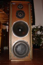
Hello to all the Ditton lovers!
Very interesting thread!
I'll have a few questions especially for Tonedef2, but first here is my story.
I've been lucky few months ago to buy a pair of Ditton 66. I bought them cheap because one mid-range driver was destroyed.
These are from 1976 and of the "woody type" with the large dust cap and an hard-wired X-over similar of the Grahame's one (see post #34). I re-caped it with MKP caps from SCR.
Before trying to buy a new I tried to restore the faulty mid.
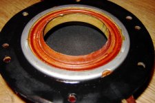
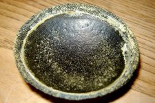
The dome was completely unglued from its suspension and worst the wire of speaker coil was broken (as you can see on the photos in the next posts). I think the previous owner powered them after some period of storage, without noticing that the cone was unglued.
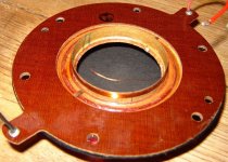
I re-glued the dome using a vinylic glue, and using a big magnifying glass and a lot of patience I soldered the broken wire.
Good news the sound of the repaired mid is for me almost undistinguishable from the other one. I said almost because on some very few tracks, featuring vibraphone or piano recorded with a lot of dynamic, I can hear a little buzzing from the mid. Too bad I like Milt Jakson very much....
I read the whole thread and I've been very interested by Tonedef2 MD-500 restoration, too bad I haven't found this thread earlier.
Tonedef can you tell us more about this "strange 2 piece arrangement that will result in all the MD500’s buzzing and or low output" and about the material that had to be trimmed as over time it had stretched? It would be very helpful. I'd like to know also which glue you've used.
Thanks a lot!
Hello to all the Ditton lovers!
Very interesting thread!
I'll have a few questions especially for Tonedef2, but first here is my story.
I've been lucky few months ago to buy a pair of Ditton 66. I bought them cheap because one mid-range driver was destroyed.
These are from 1976 and of the "woody type" with the large dust cap and an hard-wired X-over similar of the Grahame's one (see post #34). I re-caped it with MKP caps from SCR.
Before trying to buy a new I tried to restore the faulty mid.
The dome was completely unglued from its suspension and worst the wire of speaker coil was broken (as you can see on the photos in the next posts). I think the previous owner powered them after some period of storage, without noticing that the cone was unglued.
I re-glued the dome using a vinylic glue, and using a big magnifying glass and a lot of patience I soldered the broken wire.
Good news the sound of the repaired mid is for me almost undistinguishable from the other one. I said almost because on some very few tracks, featuring vibraphone or piano recorded with a lot of dynamic, I can hear a little buzzing from the mid. Too bad I like Milt Jakson very much....
I read the whole thread and I've been very interested by Tonedef2 MD-500 restoration, too bad I haven't found this thread earlier.
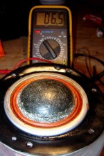
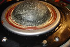
TONEDEF2: I have finished an extensive restoration of the MD 500 dome mids, won’t go into detail sep to say it involved complete disassemble, custom jig, removal of all old glues & about 18hrs of labor, they have a strange 2 piece arrangement that will result in all the MD500’s buzzing and or low output. Results? I see why theses mids where popular in the studio! Beautiful voice repro now!
This process is not for the faint of hart my custom jig was trial and error...my large 7 inch mag/light was a must have....
For one example, material had to be trimmed as over time it had stretched; very scary work as there is a cancellation dome with little margin right behind the second dome stage.
Tonedef can you tell us more about this "strange 2 piece arrangement that will result in all the MD500’s buzzing and or low output" and about the material that had to be trimmed as over time it had stretched? It would be very helpful. I'd like to know also which glue you've used.
Thanks a lot!
Attachments
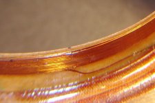
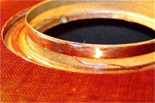

the mysterious MD500's "rubber band"
From previous posts:
As you can see on the picture the "rubber band" (if I understand well what rwtomkins mean) from my other MD-500 is starting to come apart the suspension (white parts on the edge of the ring). I' had to remove it from the one I repaired as it was partly detached already.
Should I replace it with some special glue? Indeed to me it looks more like glue than rubber.
What do you think?
From previous posts:
(quote from rwtomkins) >
(I also have a question on the mid-range speakers, which after all is where this thread started. When I got my 66s one of the mid-range units had what looked like a rubber band lying unattached to anything behind the speaker's little metal grill. I was afraid to touch these units so I gave them to Wilmslow Audio to have a look at. They said they'd put the ring back in place but on checking the other unit they'd found it was completely absent - but not to worry about it because it didn't seem to make any difference.)
Answer to rwtomkins> Was it black or white-ish? wide? Even? Please read my other post regarding our MD500'S…..I believe they have mis-informed you…..see my other posts, not may folks have seen how these where built, it is different!
As you can see on the picture the "rubber band" (if I understand well what rwtomkins mean) from my other MD-500 is starting to come apart the suspension (white parts on the edge of the ring). I' had to remove it from the one I repaired as it was partly detached already.
Should I replace it with some special glue? Indeed to me it looks more like glue than rubber.
What do you think?
Attachments
*
Hello everyone,
Very very nice work jmimac....I wish I could solder like that.
***************
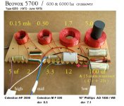
At my local resale shop I found a pair of Beovox 5700s containing Celestion MF-500 mids--which I'll hold for spares. The DCRs are okay, but I have yet to do a listening test as my 66's are in storage until March when the weather warms and the listening room is once again above freezing and habitable. So I'm not able to check the "T" numbers on my mids, but I know that the earlier blackies are mF-500s, and the later woodies are mD-500s.
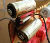
The rest of the Beovox 5700s were in very bad shape.....the cabinets were trashed, the 10" Phillips woofers needed new dust caps, the Celestion HF-2000 tweeters were toasted, and the crossover boards and some large caps suffered serious burns from overheated resistors. The problems were the same on both boards.....resistors burned away part of the board, and destroyed nearby 50uf caps. Those caps were very low voltage, too (35v). And thinking of the formula that Alan posted earlier, 35 volts is cutting it close there.
I'll post a photo of the Beovox crossover. Notice that instead of the Ditton's 500 & 5000 hz crossing, the Beovox crosses at 600 & 6000 hz.
***************
Also from the resale shop-- I really should stay away from there -- were two pairs of 1970s JBLs (10" two-ways & 10" three-ways) that made it into my car and became my winter project. This will include new foam surrounds on the woofers; all new crossovers based on recent driver measurements and crossover designs done by a guy in Denmark; new dampening materials; and, eventually, new finishes on the cabinets.
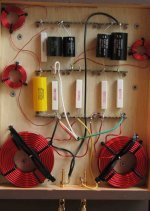
Using all new boards, coils, caps, and resistors, I have just finished (after experimenting with three different layouts) building the crossovers for the pair of JBL two-ways. And this led me to re-think my earlier rebuilds of the Ditton crossovers.
For those who have the older point-to-point boards (where the coils can be easily removed by undoing the machine screws); and perhaps for those who are having difficulty with the newer PCB boards (which I have not studied); and also assuming that one wants some flexibility for future modifications, I would recommend that a 66 rebuild be made on a new board....using your existing reclaimed coils, some new soldering strips (via ebay), new caps of your choice, and a flexible layout (similar to that seen on my JBL board), which will allow for easy (or easier) cap changes, and the addition of resistors. There's about three inches of space between the soldering strips on the new boards, which allows for most sizes of caps and resistors, and allows for easy bridging and connection.
Had I originally done such a layout for my 66 rebuilds, it would be a cinch to go back now and add the three resistors that Alan recommends.
More later...
sba
Hello everyone,
Very very nice work jmimac....I wish I could solder like that.
***************
At my local resale shop I found a pair of Beovox 5700s containing Celestion MF-500 mids--which I'll hold for spares. The DCRs are okay, but I have yet to do a listening test as my 66's are in storage until March when the weather warms and the listening room is once again above freezing and habitable. So I'm not able to check the "T" numbers on my mids, but I know that the earlier blackies are mF-500s, and the later woodies are mD-500s.
The rest of the Beovox 5700s were in very bad shape.....the cabinets were trashed, the 10" Phillips woofers needed new dust caps, the Celestion HF-2000 tweeters were toasted, and the crossover boards and some large caps suffered serious burns from overheated resistors. The problems were the same on both boards.....resistors burned away part of the board, and destroyed nearby 50uf caps. Those caps were very low voltage, too (35v). And thinking of the formula that Alan posted earlier, 35 volts is cutting it close there.
I'll post a photo of the Beovox crossover. Notice that instead of the Ditton's 500 & 5000 hz crossing, the Beovox crosses at 600 & 6000 hz.
***************
Also from the resale shop-- I really should stay away from there -- were two pairs of 1970s JBLs (10" two-ways & 10" three-ways) that made it into my car and became my winter project. This will include new foam surrounds on the woofers; all new crossovers based on recent driver measurements and crossover designs done by a guy in Denmark; new dampening materials; and, eventually, new finishes on the cabinets.
Using all new boards, coils, caps, and resistors, I have just finished (after experimenting with three different layouts) building the crossovers for the pair of JBL two-ways. And this led me to re-think my earlier rebuilds of the Ditton crossovers.
For those who have the older point-to-point boards (where the coils can be easily removed by undoing the machine screws); and perhaps for those who are having difficulty with the newer PCB boards (which I have not studied); and also assuming that one wants some flexibility for future modifications, I would recommend that a 66 rebuild be made on a new board....using your existing reclaimed coils, some new soldering strips (via ebay), new caps of your choice, and a flexible layout (similar to that seen on my JBL board), which will allow for easy (or easier) cap changes, and the addition of resistors. There's about three inches of space between the soldering strips on the new boards, which allows for most sizes of caps and resistors, and allows for easy bridging and connection.
Had I originally done such a layout for my 66 rebuilds, it would be a cinch to go back now and add the three resistors that Alan recommends.
More later...
sba
Correction to my Post #183 - Resistors
I should have proof-read my text before Posting !
Sorry sba, and other readers, I divided instead of multiplying the ESR factor - {its an increase and not a decrease at higher frequencies} .
4 ohm/5 watt {or 3.9 ohm} non-inductive in series with the 4uF.
For the other two resistors in sba's case :-
1.2 ohm and 4.3 or 4.7 ohm will give better damping, particually when their parallel combination is considered at the higher frequencies where the caps have low reactance.
These are available in a small physical size, very good quality resistor for about $2- each :-
Mills MRA-5 from partsconneXion.com , all in 5 watt :-
1R2 ; 3R9 ; 4R7 , and other values I will be specifying for the 24uF, and sba's parallel 10uF + 15uF, and for optimum capacitor combinations to sum to 75uF.
alan-1-b said:
Hi sba,
Solutions :- an ESR simulating resistor in series with each cap.
1 ohm/5 watt non-inductive in series with the 4uF,
1 ohm/5 watt ** ** ** ** ** ** 62uF,
4 ohm/5 watt ** ** ** ** ** ** 10uF.
.
I should have proof-read my text before Posting !
Sorry sba, and other readers, I divided instead of multiplying the ESR factor - {its an increase and not a decrease at higher frequencies} .
4 ohm/5 watt {or 3.9 ohm} non-inductive in series with the 4uF.
For the other two resistors in sba's case :-
1.2 ohm and 4.3 or 4.7 ohm will give better damping, particually when their parallel combination is considered at the higher frequencies where the caps have low reactance.
These are available in a small physical size, very good quality resistor for about $2- each :-
Mills MRA-5 from partsconneXion.com , all in 5 watt :-
1R2 ; 3R9 ; 4R7 , and other values I will be specifying for the 24uF, and sba's parallel 10uF + 15uF, and for optimum capacitor combinations to sum to 75uF.
Potting the air-cored inductors
Thanks for the arcane info posted!
My 66s are early blackies eg. mid driver is MF500 rather than MD500 (no other part number is marked).
The windings on bass coils moved when poked.
Am told that speaker sound improves if the coils are potted in thermally-conductive epoxy so that they cannot physically move.
Total cost only £23 including next day UK delivery from RS Components (part 552-668) 😀
http://uk.rs-online.com/web/search/searchBrowseAction.html?method=getProduct&R=0552668
Moulds - 500g yoghurt pots for the bass coils, 150g yoghurt pots for the mid coils, and Yakult for the small coils. All 5 coils required exactly one epoxy pack per crossover.
Preserved a void in the centre of the coils by inserting cylindrical marker pens that were removed before the epoxy set fully.
---
I expected the bolts and nuts securing the coils to the board to be brass. Not exactly - the head was attracted to a speaker magnet when placed near, and so is made of steel. Still, the bolt shank and nut are indeed of brass.
Having this piece of steel near the centre of the coil increases its inductance slightly, with the adverse effect of some hysteresis. Air cored coils are supposed to handle larger signals and remain more linear than ferrite-cored inductors. Even if small, this steel has more hysteresis than ferrite, I guess.
I propose to dispense with the steel-brass bolts - instead fixing each coil with plastic cable ties.
Then if the crossover frequency for the bass unit rises, by how much? 😡
Comments most welcome
Thanks for the arcane info posted!
My 66s are early blackies eg. mid driver is MF500 rather than MD500 (no other part number is marked).
The windings on bass coils moved when poked.
Am told that speaker sound improves if the coils are potted in thermally-conductive epoxy so that they cannot physically move.
Total cost only £23 including next day UK delivery from RS Components (part 552-668) 😀
http://uk.rs-online.com/web/search/searchBrowseAction.html?method=getProduct&R=0552668
Moulds - 500g yoghurt pots for the bass coils, 150g yoghurt pots for the mid coils, and Yakult for the small coils. All 5 coils required exactly one epoxy pack per crossover.
Preserved a void in the centre of the coils by inserting cylindrical marker pens that were removed before the epoxy set fully.
---
I expected the bolts and nuts securing the coils to the board to be brass.
Not exactly - the head was attracted to a speaker magnet when placed near, and so is made of steel. Still, the bolt shank and nut are indeed of brass.Having this piece of steel near the centre of the coil increases its inductance slightly, with the adverse effect of some hysteresis. Air cored coils are supposed to handle larger signals and remain more linear than ferrite-cored inductors. Even if small, this steel has more hysteresis than ferrite, I guess.
I propose to dispense with the steel-brass bolts - instead fixing each coil with plastic cable ties.
Then if the crossover frequency for the bass unit rises, by how much? 😡
Comments most welcome
- Home
- Loudspeakers
- Multi-Way
- Celestion 66 needs mid-range