VR Tube Question

I don't know if this is a problem or not so I thought who better to ask?
I built a pre-amp with two VR-105 tubes in series to regulate my B+ at 210V. My voltage is stable at that point during testing and the unit sounds wonderful to my ears. However, one of the tubes (the one on the right) has a small flicker over about 1/8th of the circumference at times. By that I mean a darkening and not a flare up. Is this a problem or a sign I should worry about?

I've tried swapping tubes as well as replacing them and the issue remains.

VlHg1RD.jpg
[/IMG]

Connex Electronics, what about this company?

https://www.diyaudio.com/forums/solid-state/364294-aem6000-based-100w-amp.html#post6447289

When SuzyJ published her nice looking pcb I did some Googling and came over Connex Electronics. Nowhere on there webpage they reveal who they are or where they are located. The domain name is also protected so no clues there. I notice also that we have a couple companies with the same or similar name.

Canterbury Windings Audio grade toroids

These are custom audio grade toroids handcrafted by Terry at Canterbury Windings, one of, if not the best toroid manufacturers in the UK - incredibly well made, they will make the ultimate power supply.

This is a set for amps requiring front and backend supplies and as such was specified for an upgraded NCC200 amp. I would ideally like to sell these as a set unless there is interest for both types.

here are the traffo specs, I'll provide fixing bolts and washers:

2 x

Power rating: 300VA
Primary: 0-240V @ 50Hz
Electrostatic screen
Secondaries: 35-0-35V @ 4.29A rms
GOSS band
Regulation: approx 7%
Estimated dimensions: 124 x 54mm away from leadouts
Mounting: central M8 x 30mm threaded insert in potted centre
Audio grade construction

2 x

Power rating: 40VA
Primary: 0-240V @ 50Hz
Electrostatic screen
Secondaries: 40-0-40V @ 0.5A rms
GOSS band
Regulation: approx 13%
Estimated dimensions: 86 x 49mm away from leadouts
Mounting: central M5 x 25mm threaded insert in potted centre
Audio grade construction

Offers around £150 for the set including postage UK

Attachments

  • IMG_3826.JPG
    IMG_3826.JPG
    218.5 KB · Views: 451
  • IMG_3827.JPG
    IMG_3827.JPG
    233.3 KB · Views: 456
  • IMG_3804.JPG
    IMG_3804.JPG
    190.3 KB · Views: 467

Krell KSL Preamp

Now that my KST-100 is complete, I'm planning to change the electrolytics in my matching KSL line stage preamp from the early 90's. The factory installed primarily Sprague 511D electrolytics in the power supply and audio sections. This amp uses 18ea 1000uf/25V on the main board, and 1k,470,and4700uf for the power supply section. All factory Spragues (80D for the 4700's).


My plan is to use quality Nichicon long life caps (ie UHW) series or similar in the power supply. I was looking at using Elna Silmic II's for the 1k/25V for the main board, but they are too tall for the case; ie I can't use 35.5mm length caps in this preamp.


Do you guys have a suggestion for the main board?

Attachments

  • KSLa.jpeg
    KSLa.jpeg
    406.7 KB · Views: 180

Nakamichi Pre CA-5 Mk1 Recap

Hi all
I plan to "recap" my Nakamichi CA-5 Mk1. I would like to replace only the electrolytic capacitors.

My question is: Are there any electrolytic capacitors in the "signal path" (All stages, line, phono)? If not, can I replace them with panasonic FMs without any degradation in sound quality?

See the service manual in the attachment.
Thank you.

Attachments

Need to match Mosfet output devices in Creek 5350SE?

I will be attending to a Creek 5350SE integrated amplifier, schematic attached, which has been repaired previously by someone else. Two HUF76639P3 devices on the right channel (Q115 and Q118 - add 100 to get part numbers for right channel) have been replaced with imperfect substitutes and the voltage across R125 (which should be 600mV) was cranked up to nearly 1.2V to compensate. (It appears Q115 and Q118 aren't logic level devices, but they should be.) All other components appear original.

The power amp section schematic I've attached is found readily online. Mike Creek was great, promptly emailing me the entire amp schematics and layout documents and confirming IRL2910 are suitable replacements for the HUF76639P3, which are now obsolete and almost unobtainable. He also advised I change all four output devices on the right channel, not just the suspect ones. So far so good.

However, I have another question, which I could ask Mike Creek, but don't want to needlessly trouble him again: I have come across the importance of matching devices, eg: http://passdiy.com/pdf/matching.pdf and thought I would indeed need to (so they evenly share the load), but was just wondering if this is correct. Many thanks for any helpful info!

Attachments

Hi from France

Hello everyone !!

I've made a registration today to ask a few questions about audio electronics/repairment/adaptations.

I hope I'll find here some asnwers.

Could someone point me the right forum category where to ask questions about :

- Adapting a car amplifier into a home use ; And the supplies choice for it.
- And using some parts from another amp maybe

-The reviewing of an old amplifier that makes a sound like : "Ooooooohhhmmmm", and "Splat !" When it turns off.

Have a nice one !

Mika54 B.

The Intellectual People Podcast -Blue Coast Records Cookie Marenco

We all get a chance to hear from 5 Time Grammy Nominated Cookie Marenco. We talk about studio equipment requirements, artist discovery and of course how she records and produces some of the best DSD recordings available on the Sonomoa DSD Recording System. We even talk about NPR's Tiny Desk Series and The Bluebird Cafe. Any music lover is sure to enjoy this candid conversation!

Please be sure to watch, like and subscribe!

Does digital sound better? | Blue Coast Records and Cookie Marenco - YouTube

Attachments

  • Blue Coast Thumbnail.jpg
    Blue Coast Thumbnail.jpg
    248.8 KB · Views: 69

PSB powered subwoofer sleeping

As the handle suggests, I'm new here. This is my first question, and I hope I'm following the rules here. I have a PSB century 2i 10" powered subwoofer. It has no option to remain on all the time, and the "auto on" feature is a nuisance, as it often falls asleep and doesn't wake when it should. I've adjusted its level, so that the AVR driving its input is +2db. I may lower its trim even more, so that the AVR has to send a hotter signal, in the hopes of keeping it awake. I've also turned on "extra bass" in the AVR, meaning the sub should be receiving a signal all the time, and not just when there's something in the LFE channel.


All this to say, would it be safe to add a small DC offset to the input of this powered sub, in order to keep it on all the time? I was thinking literally 1 volt or so. I'm hoping there's a decoupling capacitor in the signal path somewhere, so that DC offset never actually reaches the speaker. It's an older discreet amp, with 2 output transistors and a huge 40V dual rail supply, rather than a chip amp. Thanks in advance.

FS: Parts for tda7293 xmas amp

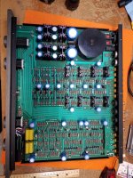
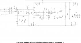
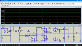
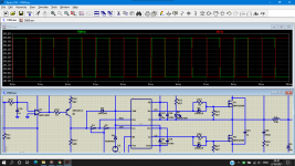
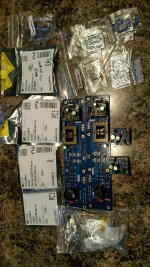
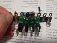
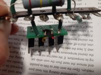
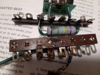
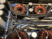
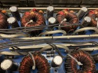
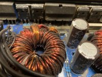
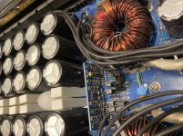
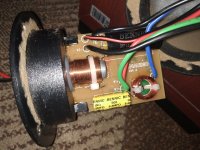
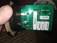
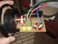
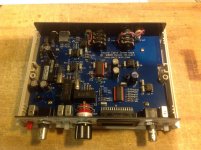
I have, what should be, the full BOM for the xmas amp shown here
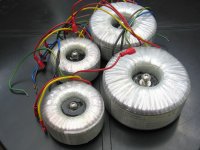
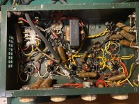
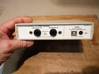
Xmas Amp - Dibya's TDA7293 by Jhofland
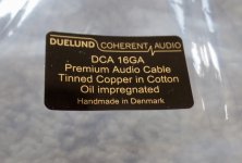
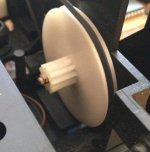
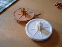
brand new in sealed bags from Mouser. Enough parts to populate both boards. The inductors on the list may or may not work. They were mentioned in a post in the thread but you may need to wind your own per the instructions in the thread. You will also need insulator and shoulder washer for mounting the chips to heatsink (and heatsinks)

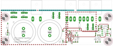
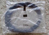
The 2 PCBs come for free with the parts.

SOLD

here's the parts list, please verify it is all that is needed and that I didn't miss anything:


Mouser #: 810-FG28C0G1H470JNT0
Mfr. #: FG28C0G1H470JNT00
Desc.: Multilayer Ceramic Capacitors MLCC - Leaded Multilayer Ceramic Capacitors MLCC - Leaded RAD 50V 47pF C0G 5% LS:5mm
C28 2)

Mouser #: 505-FKP2G002201D00JS
Mfr. #: FKP2G002201D00JSSD
Desc.: Film Capacitors Film Capacitors FKP 2 220 pF 400 VDC 4.5x6x7.2 PCM5
C10 2)

Mouser #: 505-MKS2D031001A00JI
Mfr. #: MKS2D031001A00JI00
Desc.: Film Capacitors Film Capacitors 0.1 uF 100 VDC 5%
C3, C4, C17, C18 8)

Mouser #: 505-MKP4D041005D00KS
Mfr. #: MKP4D041005D00KSSD
Desc.: Film Capacitors Film Capacitors 1.0 uF 100 VDC 10%
C101, C127 4)

Mouser #: 667-ECW-FD2W105J
Mfr. #: ECW-FD2W105J
Desc.: Film Capacitors Film Capacitors 450VDC 1.0uF 5% MPP L/S=15mm
C1, C27 4)

Mouser #: 810-FG28X5R1H105KRT0
Mfr. #: FG28X5R1H105KRT00
Desc.: Multilayer Ceramic Capacitors MLCC - Leaded Multilayer Ceramic Capacitors MLCC - Leaded RAD 50V 1uF X5R 10% LS:5mm
C12, C13, C14, C15, C 12)

Mouser #: 505-MKP4F044706F00JS
Mfr. #: MKP4F044706F00JSSD
Desc.: Film Capacitors Film Capacitors 4.7uF 250 Volts 5%
C201 2)

Mouser #: 667-ECA-1JHG100
Mfr. #: ECA-1JHG100
Desc.: Aluminum Electrolytic Capacitors - Radial Leaded Aluminum Electrolytic Capacitors - Radial Leaded 10uF 63V
C7, C8, C19, C20, C21 16)

Mouser #: 647-UES1C101MPM
Mfr. #: UES1C101MPM
Desc.: Aluminum Electrolytic Capacitors - Radial Leaded Aluminum Electrolytic Capacitors - Radial Leaded 16volts 100uF 85c 10x12.5 5LS
C2 2)

Mouser #: 647-UKZ1H101MHM
Mfr. #: UKZ1H101MHM
Desc.: Aluminum Electrolytic Capacitors - Radial Leaded Aluminum Electrolytic Capacitors - Radial Leaded 50volts 100uF 85C 12.5X20 5LS
C16 2)

Mouser #: 667-EEU-FC1J221S
Mfr. #: EEU-FC1J221S
Desc.: Aluminum Electrolytic Capacitors - Radial Leaded Aluminum Electrolytic Capacitors - Radial Leaded 220uF 63V
C5, C6, C9, C11 8)

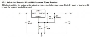
Mouser #: 78-1N5059-TR
Mfr. #: 1N5059TR
Desc.: Rectifiers Rectifiers DIODE 2A 200V
D1, D2 4)

Mouser #: 78-1N4148
Mfr. #: 1N4148TR
Desc.: Diodes - General Purpose, Power, Switching Diodes - General Purpose, Power, Switching 100V Io/150mA T/R
D3, D8, D9 6)

Mouser #: 621-1N4004
Mfr. #: 1N4004-T
Desc.: Rectifiers Rectifiers Vr/400V Io/1A T/R
D4, D5, D6, D7 8)

Mouser #: 538-39-29-9063
Mfr. #: 39-29-9063
Desc.: Headers & Wire Housings Headers & Wire Housings 6 CRT VERT HEADER
J1 2)

Mouser #: 538-22-23-2021
Mfr. #: 22-23-2021
Desc.: Headers & Wire Housings Headers & Wire Housings VERT PCB HDR 2P TIN FRICTION LOCK
J2 2)

Mouser #: 538-39-29-9043
Mfr. #: 39-29-9043
Desc.: Headers & Wire Housings Headers & Wire Housings 4 CKT VERT HEADER
J3 2)

Mouser #: 994-SER1590-102MLB
Mfr. #: SER1590-102MLB
Desc.: Fixed Inductors Fixed Inductors 1uH Shld 20% 27A 940mOhms
L1 2)

Mouser #: 594-5083NW2R200JA100
Mfr. #: PR02000202208JA100
Desc.: Metal Film Resistors - Through Hole Metal Film Resistors - Through Hole 2watt 2.2ohms 5%
R8 2)

Mouser #: 594-5083NW10R00J
Mfr. #: PR02000201009JR500
Desc.: Metal Film Resistors - Through Hole Metal Film Resistors - Through Hole 2watts 10ohms 5%
R5 4)

Mouser #: 660-MF1/4DC2150F
Mfr. #: MF1/4DC2150F
Desc.: Metal Film Resistors - Through Hole Metal Film Resistors - Through Hole 215ohm 1% 100PPM
R11, R14 4)

Mouser #: 603-CFR-25JB-52-750R
Mfr. #: CFR-25JB-52-750R
Desc.: Carbon Film Resistors - Through Hole Carbon Film Resistors - Through Hole 1/4W 750 Ohm 5%
R3, R4 4)

Mouser #: 660-MF1/4DC2371F
Mfr. #: MF1/4DC2371F
Desc.: Metal Film Resistors - Through Hole Metal Film Resistors - Through Hole 2.37K 1% 100PPM
R12, R13 4)

Mouser #: 660-MF1/4LCT52R103J
Mfr. #: MF1/4LCT52R103J
Desc.: Metal Film Resistors - Through Hole Metal Film Resistors - Through Hole 1/4 WATT 10K OHM 5%
R7 2)

Mouser #: 660-CFS1/4CT52R203G
Mfr. #: CFS1/4CT52R203G
Desc.: Carbon Film Resistors - Through Hole Carbon Film Resistors - Through Hole 20K OHM 2% 1/4W
R1, R2, R6 6)

Mouser #: 660-MF1/4DCT52R3002F
Mfr. #: MF1/4DCT52R3002F
Desc.: Metal Film Resistors - Through Hole Metal Film Resistors - Through Hole 1/4W 30K ohm 1%
R10 2)

Mouser #: 660-MF1/4DCT52A4752F
Mfr. #: MF1/4DCT52A4752F
Desc.: Metal Film Resistors - Through Hole Metal Film Resistors - Through Hole 1/4 WATT 47.5K OHM 1%
R15 2)

Mouser #: 660-MF1/4CCT52R1003F
Mfr. #: MF1/4CCT52R1003F
Desc.: Metal Film Resistors - Through Hole Metal Film Resistors - Through Hole 100K 1% 50PPM
R20 2)

Mouser #: 660-MF1/4DCT52R3323F
Mfr. #: MF1/4DCT52R3323F
Desc.: Metal Film Resistors - Through Hole Metal Film Resistors - Through Hole 1/4W 332K ohm 1%
R16, R17, R18, R19 8)

Mouser #: 511-TDA7293V
Mfr. #: TDA7293V
Desc.: Audio Amplifiers Audio Amplifiers 100W Audio Amplifier
U1 2)

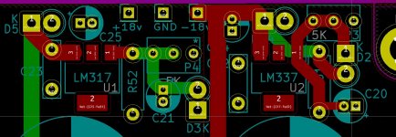
Mouser #: 595-LM317LCLPR
Mfr. #: LM317LCLPR
Desc.: Linear Voltage Regulators Linear Voltage Regulators 3-Trm 100mA Adj Pos Voltage Regulator
U2 2)

Mouser #: 926-LM337LZ/NOPB
Mfr. #: LM337LZ/NOPB
Desc.: Linear Voltage Regulators Linear Voltage Regulators 3-Term Adj Reg
U3 2)

Mouser #: 595-TL071BCP
Mfr. #: TL071BCP
Desc.: Operational Amplifiers - Op Amps Operational Amplifiers - Op Amps Low-Noise JFET-Input Op Amp
U4 2)

Attachments

  • xmasamp.jpg
    xmasamp.jpg
    999.2 KB · Views: 174

Midrange driver for high SPL 3 way - AE TD6M vs 18 Sound 6ND430

I'm thinking of a 3-way with 15" woofer (maybe B&C 15BG100), 1" tweeter (maybe Scanspeak D2905/9700) and a suitable midrange (maybe ~300Hz-~3.5KHz).

I would have liked to consider the Volt VM572 - the speaker that inspires me is the ATC SCM150 ASL Pro... but I don't want to spend that much.

I would really like to use the 18Sound 6ND430 because of its cost but I am also looking at the AE TD6M, because I've had great experiences with the TD15H (I've built two huge subs with them, and they're fantastic).

How do these two drivers compare? Are there any others I should consider?

Solving IR2110 not work

I make circuit basic Class D amp using IR2110. but some mistake i dont know. the IR2110 not pulsing to activate mosfet. anyone can help me..?

Attachments

  • D900.jpg
    D900.jpg
    439.5 KB · Views: 104
  • D900 ss.png
    D900 ss.png
    99.2 KB · Views: 92
  • D900 OUT IR.png
    D900 OUT IR.png
    90.7 KB · Views: 93
  • D900 IN.png
    D900 IN.png
    93.3 KB · Views: 90
  • D900.asc
    D900.asc
    15.6 KB · Views: 58
  • IR2110.asc
    IR2110.asc
    11.6 KB · Views: 59

DIYINHK Supply: Please help to make it work...

Hi everyone!

A couple of years ago I bought two of these DIYINHK Power Supply DIY sets and built them up. Only now did I get to put them to work, but they only work with open load so far 😱. The items are EOL, but I'd like to use them anyway:

The driven load needs +/-15V with max. 800mA per Rail.
The DIY supply supposedly drives up to 1.5A per rail at +/-15V.
The Supply used so far is a Meanwell PD-2515 which matches the current needs.
The measured actual current drawn by the load from the +15V rail is 590mA and 550mA from the -15V rail.

Observation is that the Output voltage of the DIY supply drops from +/-15V to +/-12V on one unit and even down to 10.5V on the other unit when the load is applied.

I have reverse engineered the board schematic (hopefully correctly...) and as comparison a basic application schematic from the LT3042 datasheet. Please see attachments.

Any hint what may be wrong or how I could proceed to make the boards work as intended would be much appreciated.

Thanks and Regards,
Winfried

Attachments

  • LT3042 Application.png
    LT3042 Application.png
    80.8 KB · Views: 198
  • DIYINHK Application.png
    DIYINHK Application.png
    113.1 KB · Views: 186

M2X boards populated

M2X boards populated SOLD

I am offering my populated boards for anyone interested.
Not tested, so enter at your own risk.
So, all of the boards offered in the original purchase from DIY with 2 populated IPS7 and 2 populated Mountain View boards as well as 2 IPS6 boards.
Reason for selling is, my J2 is not coming out of my main system.
It is dead silent and sounds amazing, cant ask for more than that, thanks Jeff Young for the boards.
Better pics on request.
250.00 shipped CONUS

sold

Attachments

  • IMG_20210217_203325407.jpg
    IMG_20210217_203325407.jpg
    969.8 KB · Views: 230

+/_ rails tracking

Hi Folks

I am sure that somewhere in the not too distant past, I read about a technique whereby connecting a capacitor between the + and - rails (not 0 volts) would cause the two rails to track each other fairly closely.

I can't find the details about the technique and how to choose the value of the cap. Has anyone got any information or knowledge about it

The application is a +/- 40 volt supply at about 4.5 Amps for a Class A amplifier that is housed in a separate chassis from the amp and connected by an umbilical cord.

The configuration is:
Toroidal transformer -> Diode bridge -> bank of 45,000uF initial smoothing caps -> umbilical cord to amp chassis -> bank of 30,00uF reservoir caps -> Cap multiplier -> amp module.

I think that the 'tracking caps could probably go anywhere in the chain, but gut feeling says on the second bank of reservoir caps.

Thanks for any help

Mike

DHT regulator for 3-10A continuous 10-21V out.

I have designed a regulator for high current directly heated tubes, tubes like the 211/845 on the low end of the current scale and 833 (10V 10A) on the high end of the current scale.


I want to start my own company, and this is perhaps one of the last times you can get this kind of product from me at hobby prices.


The module functions as a automatically adjusted current source, and has voltage control for low frequency, and behaves as a current source for high frequency.


I currently have eight boards left that aren't allready spoken for out of a total PCB order of 20 boards.


The boards measure 50x160mm and are 1.6mm thick green FR4 epoxy with ENIG-ROHS gold plated pads and 2Oz copper. There is a strip approximately 15mm wide along the length of the board that can be used to mark out the mounting holes of the TO-247 Devices.


Everything needed for the supply except for the bridge rectifier and optional secondary fuse is included on the board. It takes the output of the bridge rectifier and or LT4320 based ideal bridge and stores the charge in the two on board 22000uF capacitors.


The modules are adjustable in its maximum current output by means of swapping out the TO-247 current sense resistor for a different value.


Design specifications where as follows:


Voltage output : Adjustable between 7.5 and 21VDC

Current output : Continuous 3-10A peak for starting cold heaters 5-15A.

Dropout voltage : <=1.5V

Regulation : 0.1% per volt.

Residual hum+ noise : <=2.5mVRMS at rated current output between 10-100Khz.


Suggested retail for one tested board is 125Eur , you get one tested board, and another one without the ROHS-ENIG finish and 1Oz copper instead of 2Oz copper for marking out the holes. Tested boards are de mounted from a test heat-sink, and might have some thermal grease on the semiconductors and FETS. They are complete with everything, mounting hardware and all, the only thing you need to do is mark out 8 holes, four M3 and four M4 on your heatsink of choice.


I am currently taking solid reservations for these modules at a reservation cost of 25Eur to be deducted from the price of 125 Eur for one tested completed module. The price will increase to 175 Eur once all the specifications and correct functioning of the modules has been verified. If it doesn't work or meet the specifications. I will refund you the downpayment on the modules.


From you i need to know what kind of current and voltage range you want as this determines the working voltage of the capacitors, and the value of the shunt resistor.


I have been looking at a company to manufacture 6-8mm thick 80x160MM copper heat spreaders so i can supply. complete modules that bolt on to an existing heat sink with ease, but the prices quoted so far make it a rather expensive proposition.


I will answer any questions you may have through a PM.


Cheers,

V4lve

Attachments

  • 10A scalable regulator board.png
    10A scalable regulator board.png
    230.3 KB · Views: 250

Mystery JFET - E204

Hi folks


Given the increasing scarcity of JFET types, I grabbed 50 of these, I think they are made by Siliconix in Taiwan and the model number is E204, but that's all I know.


Anyone able to shed some light on these JFETs?


The seller was unable to find much info:

E204 N-Channel JFET Transistor (Pk of 10) | eBay

"I have been unable to find much data on these transistors but believe them to be N-Channel JFET (Confirmed by my component tester)


With the flat face towards you the pin-outs form L to R are G - S - D

Marked tai-wan on the side"

Attachments

  • s-l501.jpg
    s-l501.jpg
    11.2 KB · Views: 115
  • s-l1600.jpg
    s-l1600.jpg
    88.5 KB · Views: 112
  • s-l1601.jpg
    s-l1601.jpg
    184.3 KB · Views: 110

Telefunken Concerto 8 hums

Hi guys,
I have this beautiful Telefunken Concerto 8.
It still works but has a nasty 100Hz hum.

An externally hosted image should be here but it was not working when we last tested it.

Bag of Doritos for size (sorry.)

Now, I checked the obvious things. These are my initial observations:

1) without the EL84, the hum is gone.
2) with the EL84 but without the last preamp tube, hum is still there.

So, the problem must be in the EL84 stage, right?

Here are the voltages I measure:
concerto8.png


Apart from everything being a tad low (note the voltage switcher is set to 240V, while we have 230V here), everything looks good.

B+ is supposed to be a 270V rail with a 50uF cap. I'm measuring 240V with 3.7V Vrms ripple.
B2+ is supposed to be a 230V rail with a 50uF cap for the preamp tubes, I'm measuring 209V with 3.1V ripple. I measured the supply caps, they are spot on 50uF. Didn't measure ESR.

I checked the resistors around the EL84, they are spot on after 60 years!
Current through the EL84 is about 40mA, that's good (checked the cathode resistor, it is 120 ohm).
Current throught the g2 resistor is around 30mA, that's correct.

So it looks like the EL84 stage works fine.

I then thought that the ripple was coming in through g1.
So i shorted the point between W26 and W27 to ground (that's why I wrote 0V).
I was expecting the hum to go away, but it actually gets a bit louder! Now I'm confused...


So, voltages around the EL84 stage are good, currents are good, ripple is reasonable. But the hum's there, even if I short the input to ground.

What am I missing here?

ICEPower 100AS2 signal sense/auto-on

I have a couple of these boards on the way, and I've scoured through the documentation hoping to find out how to wire signal sense/auto-on for these, but to no avail...

Here's the docs: https://icepower.dk/download/2431/

There is just some stuff about standby mode (whatever they actually mean by that), and not signal sense like on the 200ASC documentation. But they clearly state that the As-series (like the ASC-series) have "wake-on signal sense".

Could anyone help me out? 🙂

Inrush Current, Triac Input vs No Triac Experiment

This is in response to folks challenging the premiss I presented claiming turning on a high power amp at the zero crossing will result in less inrush current. A couple forumites pointed out Douglass Self and some other prominent audio types claimed that a zero cross start results in more inrush current not less due to the back EMF being generated slower thus increasing the current quicker. (?)
I constructed an assembly that simply interrupts the neutral line of a power cord and inserts a 0.1ohm resistor in series. I used my dual channel Tektronix to record waveforms during start up. See the attached photos. The jig uses a terminal block a current sense R and the two scope probes.
The best way to set up the scope is to not count on the neutral being at GND potential but rather attach ch1 probe to one side of the R and ch2 probe to the other side, then set ch2 on invert and select "add ch1 to ch2". What's interesting is I initially tried interrupting the hot line with the sense R. This didn't work well because I assume the scopes common mode rejection goes to hell the higher the V is away from it's third prong ground as I witnessed a constant 60hz sign wave of small amplitude even with no current being drawn. On the other hand interrupting the neutral worked really well with no sign of 60hz with no current being drawn.
The amp I'm using is a Peavey CS800, 400W/ch comercial stereo amp with huge transformer and filter caps producing +/-80Vdc. The unit weighs 53lbs most of which is the massive transformer (8"x6"x6"). As designed it uses a triac to pass the input AC which is primarily there to protect the power switch as only the triac firing current goes through the switch. But......I maintain there's a secondary benefit - reduced inrush which several forumites challenged.
Capturing the turn on event when a zero cross occurs with a triac is easy as it will only turn on at a zero cross. Capturing without - not soe easy as I had replaced the triac with a jumper wire. I simply plugged in the power cord, asynchronously with the 60hz of course, to generate waveforms on the scope. I performed many turn-ons and recorded the waveform on the scope snapping a shot of the screen with my phone so that I could catch possibly the worse case.
All of this lined up with what i expected to see.

Observations:
1. The current is drawn as soon as the V overcomes the forward voltage required to turn on the rectifier diodes to charge the caps.
2. The voltage across the R, and thus the current decays as the caps charge up in light of this.
3. It was random whether the first peak would be a negative or positive pulse in both cases with and without triac.

Results:
Without triac, the worse case I got with five turn-on tries was about a 10v first peak across the 0.1ohm which equals 100amps (wow) Some were less as is expected. Keep in mind I may not have plugged it in exactly at the peak V so 10v may not be the worse case. See the attachment.
With triac, the first peak was always the same amplitude, ie 8 volts. the only difference would be whether it was negative or positive swinging as expected. This equates to 80 amps. (wow too) not much better but certainly less and not more reported by other folks.

Really this is still a lot of inrush current and I applaud the efforts to tame it with soft starts. I just wanted to dispel a theory about triac start up. The triac I used is the following - STMicroelectronics BTA40-800B $10.00 at Digikey.

Attachments

The best one-stop PCB& Assembly you're finding

website please see: PCB Fabrication and Electronic Components Assembly | Factory Direct Marketing

Our advantage: PCB assembly; Aluminum PCB; PCB components sourcing;
PCB bare boards manufacturing is our most basic service.

we located in Shenzhen, China, and also own factories in 2 provinces else.

more information if you are interested in please contact: Donna@pcbonline.com
-----------------------------------------------------------------------------------------

Article learning: what does PCB mean?

click:

Error)

Group Buy: Cordell's Super Gain Clone / Compact3886 / PSU for Chipamps

Super Gain Clone and Compact3886 are chip amps, discussed here:

Bob Cordell's Super Gain Clone PCB (LM3886) and a stripped-down version: Compact3886

The companion power supply board is small and purpose-designed to work with them:

PCB available: PSU for Chipamps , such as Super Gain Clone and Compact3886

If people sign up to buy a total (across all three board types) of 100 boards or more, I'll collect the money and send the CAD files off to fab. Then when boards are delivered to me, I'll ship them out to members who ordered.

Price will be $2 per board if total volume is less than 200 boards; dropping to $1.50 per board if total volume exceeds 200 boards. Plus a fixed $6 per shipment inside the USA, $16 per shipment to rest of world. No more than 10 boards per order, please.

No payment is needed today, just copy the list below and add your diyAudio username at the bottom. Please indicate how many of each board type you pledge to buy, using the same format that I used. Thanks!

When new pledges have stopped appearing, if we've hit 100 total boards, I'll halt the GB and start collecting the money (by sending you a PM).

For example, I pledge to buy 2 Super Gain Clone boards, 4 Compact3886 boards, and 3 PSU for Chipamps board.

Pledges:

Mark Johnson: 2 x SGC / 4 x Compact / 3 x PSU

tl072 pre-amp/mixer

Hi everyone,


At the moment I'm building a portable speaker as a project for some friend. It's a simple second hand passive hi-fi speaker that I rigged with a Chinese class-D amp powered from a 12v lead-acid battery through a DC step-up module that raises the voltage to 28 volts (I think). Everything here is working fine, I can recharge it and hooking up a music player or phone works great.


However, I also want to be able to use a microphone with it and while that does work, the signal is too low (pretty understandable as it's much lower than a phone). So I thought I'd build a simple preamp from a tl072 and use the spare op-amp circuit as a mixer or as a small secondary amplification stage if the mixing resistor turned out to attenuate the signal too much.


This has been giving me huge issues, however. For some reason, I can't get this (or other opamps I've tried recently as was getting desperate) to work properly and it's only functioning around 10-20% of the time. I've hardly been able to get to the mixing stage of the project.


What's been causing most frustration is that it sometimes does seem work on both my breadboard or when I solder it together afterwards. I made a first iteration that seemed to be working pretty well, but as soon as I actually tried to put everything together permanently there suddenly was a huge amount of distortion. After tinkering with it some more, it won't work anymore. I've been trying multiple different chips, component values and even breadboards to get it to work. I've reassembled everything a million times. Sometimes it works, sometimes it doesn't. The same circuit seems to give different results every other 5 minutes.


I've attached the schematic I've been using as my basic idea. I've tried biasing the inverting input, building a virtual ground with two resistors, but the only way it has actually worked is without either of those.


I'm not sure what to troubleshoot, replace, rebuild, scope out, check the connection of, anymore.


Any help would be greatly appreciated.


Kind regards,
Wouter

Attachments

  • Screenshot 2021-02-18 at 20.31.51.png
    Screenshot 2021-02-18 at 20.31.51.png
    187.5 KB · Views: 403

MOSFET speaker relay using VOM1271

Anyone with experience like to chime in on my speaker relay?

I am looking to use either a 5v or 3.3v supply for powering the VOM1271 in series and would like feedback mostly about any concerns using either voltage.
The nominal forward voltage of both units (1.4 ea) brings the headroom down to 5-2.8=2.2 and 3.3-2.8=0.5 respectively. Would there be any issues with headroom using 3.3v?

Thanks for input
S

SPEAKERELAY.png
VOM1271.png

Newbie in need of help

I tried my best to make this circuit as small as possible, did I position things too close together? Also can someone double check, that in general, I routed everything right. I'm a newbie, this is only the second board that I have sent to a PCB house and the first one I didn't design right.

Attachments

  • WABA_v10.jpg
    WABA_v10.jpg
    179.8 KB · Views: 75
  • WABA_v11.jpg
    WABA_v11.jpg
    220.1 KB · Views: 79
  • WABA_v12.jpg
    WABA_v12.jpg
    33.8 KB · Views: 82
  • WABA_v13.jpg
    WABA_v13.jpg
    35.9 KB · Views: 82

Series diodes for tube rectification - formulae?

I want to use two C3D02060F SIC diodes in series in a full wave rectification for a tube preamp/amp. So 8 in total. This is because I have several. I therefore need to know what resistor values (ohm, watts) to use in parallel with each diode. I would also like to know the capacitor rating and type to use in parallel with each diode.

I've slogged through the formulae on this website:

Question about diode strings in high voltage applications - Electrical Engineering Stack Exchange

I attach my calculations. This looks correct for the case quoted (3200v, 10 diodes) but for the C3D02060F SIC diodes it looks like a resistor of 30Meg, 0.5W. this seems very large. Is this right?

Is there an easier way to find the value and wattage of each resistor used with series diodes?

And what is the correct value for 2 x C3D02060F SIC diodes in series in a rectification around 300v, 200mA for the HT.

http://www.farnell.com/datasheets/2047818.pdf

Attachments

  • Screen Shot 2021-02-18 at 09.50.17.png
    Screen Shot 2021-02-18 at 09.50.17.png
    41.7 KB · Views: 218

Any 8” line arrays ?

I’ve been wrestling on dispersion vs output of an 8” driver.

I dispersion gets pretty tight on an 8”, unless you have a lot of hf climb then listen off axis (maybe w8-1772).

But let’s take an flattish 8” (w8-2145).

I find it has a sweet spot of 1 head at 7’, maybe 2 heads when shoulder to shoulder at 12’.

So a few of them should not interfere with each other much.

Maybe 4 or 6 of them in a vertical line array.

That would give a bit of bass further from it, less distortion (less cone motion), especially for those who boost the bass (me).

It keeps the whole time alignment thing together too.........

Yes, still narrow width dispersion, but maybe better sound 15’ away than 1 driver struggling....... Especially when turning it up a bit.


Thoughts ?
Ideas ?

How can I build a bridge rectifier that will last?

I've had some problems supplying my voltage regulator with rectified DC power. My rectifier designs always seem to arc over and short out.

My transformer is a Hammond 712, 293 VA 850 CT and 345 mA.
My diodes are DIODE FRED 1.2KV 8A TO220AC
and the capacitor is a Solen Film 51uF 1500Vdc PESG-CAN Series

At first I'd tried a point to point design but after the first flame out I went with a PCB that I got from parts connexion for the next four attempts.

Here are a couple of photographs of the latest flame out from today, as well as my first attempt (the point to point.) Today the electricity went across the PCB, usually my problem is the electricity arcing across the terminal lug strip. This is the fifth time now so I think I need to try something different.

I have trouble understanding why the electrons would travel across the plastic or press-board rather than through the wire. I would have thought there would be much less resistance in the metal.

Any suggestions or criticisms would be welcome.

Thanks,
Glenn

Attachments

  • 20201004_165932.jpg
    20201004_165932.jpg
    647.6 KB · Views: 481
  • 20201004_165954.jpg
    20201004_165954.jpg
    696.6 KB · Views: 481
  • 20201004_170004.jpg
    20201004_170004.jpg
    797.2 KB · Views: 476
  • 20201004_173515.jpg
    20201004_173515.jpg
    911.3 KB · Views: 467

How to curve a horn

Hi, I am looking some information on how to “curve” the construction of a horn. I can model a straight exponential horn in horesp, but how can I curve it?

15study.jpg


In this image, each section is 3” apart. But as the horn starts to curve does the 3” measurement get blended around the curve or is it a straight point to point line.

I am thinking that it would be best to find the centreline of the horn, and measure the 3” as a curved “arc length” as opposed to a straight point-to-point measurement. Is this correct?

Delta Lab Super Time Line Battery Part

Hi everybody! New here, not sure whether this is the right place to put this. I'm looking for a part...

I have a dysfunctional Delta Lab Super Time Line ADM2048 delay processor on my desk. The problem is its internal backup battery (a red cylinder with axial leads) has failed. I've looked up the part number (SAFT P/N# M0703 4483) with no luck. I'm wondering if anybody here can help.

Note: After I removed the battery and cleaned the unit a bit I powered it up and measured about 5V across the terminals where the battery used to be. If I can't find an exact part would it be possible to purchase a 5V rechargeable back-up battery, PCB-mount, and replace the old battery with that?

Attachments

  • IMG_0886.jpg
    IMG_0886.jpg
    864.7 KB · Views: 101

Thoughts on the active chain with an analog player (vinyl + DSP + AMP + speakers)

Hello everybody


After very long research, I have now put together my chain so far.


- Rega Planar 6 with Excalibur Black + Photo Preamp + MiniDSP SHD + Purifi 4 channel amp + DIY 2-way active with Purifi 6.5 midwoofer and Bliesma T34A tweeter

The plus point here is that the miniDSP can also stream Tidal and Qobuz. Although I also thought of a DIY solution for the DSP, namely a miniDSP 2x8 HD board with RasberyPi as a streamer. It would even be possible to operate 4 ways in stereo.

With the whole active history of miniDSP, however, I have a question, the mini DSP itself can only work internally at 96kHz, i.e. every signal above it will downsample. In this context it makes little sense to play audio files with 192kHz, or am I wrong. Of course, it would be more logical to use a DSP, which internally processes 192 kHz and does not do newnsamopln. But I haven't found anything like that.

Of course, there is also the question of the analog signal from the turntable. If this goes through the DSP, then of course analog is converted into digital + DSP and back again via DAC to the amplifier. I have to consider whether this is good for the analog signal: the double conversion from AD to DA. But with an active concept there is no getting around converting the analog signal from AD to DA.

Therefore I would be interested in your opinion and whether something like this has already been realized.

Thank you and best regards

Alexander

6SN7+6V6CF Linestage Pre

Here is my design for a linestage preamp I have been using for a couple years now, and I quite like it.

With 4 sets outputs, you can run a set of speakers with a level control for different drivers. Amplifiers can be had cheaply! 6SN7 as the amplifier, AC coupled to a 6V6, but taking the signal from the cathode. From that point, there are 4 x 10K dual log pots connected in parallel. Coupling cap sizes can be chosen to give a -3db HP filter of whatever you want, in this case I have 2 sets for about >80hz and the other 2>18hz.

I would be happy to hear any criticism. Maybe using a CCS source somewhere to have a real stable DC rail at the 6V6 cathodes (not sure if there is an issue there).

Can I get away with 4 x 5K dual pots in parallel? ie what is lowest impedance the 6V6 can deal with? 4 x 5k =1.25k 5VRMS/1250 = 4ma. Square that then multiply by 1250 = miniscule wattage output (.02W)

Anyway, it is something a little different I do think it sounds quite good.

Attachments

  • linestage pre schematic.jpg
    linestage pre schematic.jpg
    174 KB · Views: 206
  • studio moco fr.jpg
    studio moco fr.jpg
    108.7 KB · Views: 200
  • studio moco rear.jpg
    studio moco rear.jpg
    129.4 KB · Views: 194

Samsung SS-3390 receiver

Im looking for a schematic for this Samsung receiver model SS-3390

I have noticed my FM stereo lamp is not coming on. I switch it between mono and stereo to not hear any audible difference. It has a HA1156W IC for the FM stereo. I wonder if I may have zapped it when I used a brush to remove a deep layer of dust in it.

Anyone who might have the IC might be handy as well.

TDA7010T + LM386 + another amp

Hello,
I have this FM radio kit (attachment) build on a TDA7010T and an LM386, but would like to use another amp instead of the LM386.

I was hoping to take the TDA7010T source directly to the other amp input but, soon realised that its Vout was only 75mV, the other amp Vin is 800mV.

Is there an easy way of bringing that 75 to 800?
Or should I use the speaker output conversion to achieve a line level of 800mV?

If I use the speaker output, would it make any sense to drop the gain of the LM386 to x20, so its output would be 75mV x 20 = 1.5V so I would only need a 2:1 voltage drop.

The other amp has an input impedance of 22k.
What would be a good choice of resistors?

Can the volume pot stay where it is or should it come after the LM386 ?

Thank you

image.png

Audio Precision Portable One Dual Domain THD+n problem

Hi All!

I have a Portable One Dual Domain analyzer that passes all self tests, but after warming up measurements of THD+n start to drift towards -60dB in the 20.5kHz-21kHz (or even 22kHz). When it is cold there is a small step in the THD+n measurements at 20.5kHz but nothing so drastic.

When 20.5kHz-21kHz band is out of whack, everything up to 20kHz is perfectly fine and after 22,23kHz the THD+n returns to "normal". The selftest just misses this anomalous point.

Unfortunately the schematics are not available, but it seems to be quite closely following the design of System One, except that it does not have a 2 stage filter and the null and tune loop seems somewhat different.

I have found equivalent parts from System One service manual in my portable one and I can see that when the problem happens the NULL control voltage goes near the "null opamp" positive rail, so apparently the null error is beyond its ability to compensate. The null control voltage pretty much around +-2V on the 9.5Hz to 20.5kHz range. After that a relay clicks and the null control voltage shoots up to 12V. It stays there in the problem area and just barely gets to 10-9V going further up with filter frequency.

There is another servo loop for correcting filter tuning error and that control voltage is generally in the +-2V range when changing the filter frequency.

My problem is that I currently do not have a good idea on how to do further troubleshooting because of these servo loops. I don't know if there is a problem in the null control loop or the filter is not performing as expected for some reason after 20.5kHz. Or compensation is not working as expected.

So before taking things further apart to disconnect parts of the circuit to see what really happens after the "magical" threshold frequency is crossed, I would like to know if anyone has already seen this behavior.

Obviously other part of the problem is that analog electronics is not my strong point and the details of the filter are reaching far out of my comfort zone 🙂

Also before taking things further apart I'd like to know if there is some magic way to easily remove the digital board sitting in the metal can on top of the analog input board. I opened its can but I see no obvious way of detaching the can that is getting in my way of removing the analog input board. So before unscrewing more screws I'd like to know if there is an easy way to get the analog input/analyzer board out

Thanks!
Jaka

Tweeter / Crossover Advice

I came across this design on a Polish website.
It is an MTM design using 2 SB17NAC Midwoofers and 1 SB29RDC Tweeter.
I am thinking of going ahead with this build but would like your expert opinions on two things.
1) Does the crossover design seem ok or could it be improved.
2) Could I use the Satori TW29R tweeter instead of the SB29RDC without any changes to the crossover.
Thanks in advance.

NEP 17k amp

Anyone know what fets I can use in this amp ?

Right now it has IRFP3077 in it but as you can see they are blown and I do not know if they are original since the amp has been worked on before and the originals have been replaced at some point

Attachments

  • 6C170750-23D4-4951-940B-9FD8652F742E.jpg
    6C170750-23D4-4951-940B-9FD8652F742E.jpg
    1 MB · Views: 111
  • E8E27EAE-FD4E-416E-9207-FA86AD4A3346.jpg
    E8E27EAE-FD4E-416E-9207-FA86AD4A3346.jpg
    1 MB · Views: 80
  • A3B661B2-CE19-4E81-9608-1AFBFB563A3E.jpg
    A3B661B2-CE19-4E81-9608-1AFBFB563A3E.jpg
    1,017.8 KB · Views: 78
  • 1E099C3E-6760-4927-8EB3-D4CCDD8C2733.jpg
    1E099C3E-6760-4927-8EB3-D4CCDD8C2733.jpg
    1 MB · Views: 73

Dynaudio DM 3/7 crossover scheme

Guys need help in finding out crossover layout. I can't understand the scheme fully especially in tweeter region.

As far as i can understand woofer works in that way:

An externally hosted image should be here but it was not working when we last tested it.

Attachments

  • IMG_20191126_231418.jpg
    IMG_20191126_231418.jpg
    313.9 KB · Views: 520
  • IMG_20191126_231601.jpg
    IMG_20191126_231601.jpg
    225.4 KB · Views: 519
  • IMG_20191126_231632.jpg
    IMG_20191126_231632.jpg
    299.8 KB · Views: 586

Which amp project for me?

I am looking for my next amp project having just finished my B1Korg
Currently have an F5 and/or a couple of chip amps running my open baffle speakers that are around 95db efficient. Music tastes run from classic rock to blues. Amp only drives above say 100hz as the bass drivers have their own power.
Would like to experience a "tube" like sound and I am considering the Aelph J or the MX2.
Any opinions on the differences between the two or which amp will get me the sound I'm looking for ?

Need buffer for unbalanced line level audio

Good afternoon all,

first post here. I'm coming to this because I have an old HH Scott 340B receiver and I've been trying to get it in top shape. I thought I had an issue with it, but it turns out the real "problem" is an impedance mismatch between its tape out jacks and basically anything I'd want to hook to it. The Scott wants anything connected to have a minimum impedance of 100K ohms, whereas my ADC Sound Shaper SS-412x EQ is 47K ohms. That is enough that just having the EQ connected and powered up, even if the EQ is bypassed, destroys the bass response of the Scott on phono input. I have the same issue with my cassette deck connected directly to the Scott. With nothing hooked to Tape Out, it sounds great, although then I obviously have no line out and can't use the 412x as a spectrum display or to provide two tape loops.

more discussion of the issue here:

Scott 340B weak bass on phono? | Audiokarma Home Audio Stereo Discussion Forums

Posting in this thread as someone suggested a headphone amp might work as a buffer, and I immediately thought of the O2. I sent an inquiry to JDS Labs and got a response that the input impedance was ">10K" when I gave more detail I was told that changing the resistors would work.

"you can see that the input stage is coupled to ground via 10k resistor. Input impedance of the NJM2068D opamp is higher, but the 10k resistor will be a limiting factor. It is safe to assume 10k. You should be able to swap these resistors to 499k if you need a higher input impedance. I have not tested this setup exactly, but would from other experiments we have conducted, there should be little to no impact on overall performance."

I'm assuming he's talking about R14 and R20 and does this seem like a logical way to approach this? I've always kind of wanted to try an O2 but never had a real need for it, if I could use it both for its intended purpose and as a buffer for my tube system, that would be fantastic.

Or is there a much simpler/cheaper buffer that would work for the Scott, and can you suggest one? Thanks much. If using something else would be a better approach, let me know and I'll start a different thread.

FS: P.Millet SoundCard Interface ASSY

I have a Pete Millet interfaces for sale. This is my own unit, built exactly to specs with Front/Back Panels. Unit is in perfect condition. It is working great if you want to transform your computer/laptop into a full function audio test gear. Reason for sale, bought an other measuring setup.

For details see: Soundcard Interface

I'm selling it at USD120 + shipping + 3.5% Paypal fee (for comparison, a new one will cost around USD280 for all the components and materials).

Kindly PM me if interested.
SB

Attachments

  • IMG_20210216_103134.jpg
    IMG_20210216_103134.jpg
    421.4 KB · Views: 247
  • IMG_20210216_103142.jpg
    IMG_20210216_103142.jpg
    408.4 KB · Views: 244
  • SB_IN.jpg
    SB_IN.jpg
    151.7 KB · Views: 251

TPA3110D2 board mods

Hello.Just came to my hands a board like this.After reading the datasheet and inspecting the boards schematic i found that it has a gain of 36dB, GAIN0,GAIN1,AVCC pins are connected together and tied to Power supply voltage through a 10ohm resistor and a decoupling cap of 1uF maybe.

Output LC filters consists of 22uH coils and 1.8uF capacitors.Are theses values ok for use with 8ohm speakers?

Should an additional snubber network of 10ohms in series with 330pf cap be added from each of the class D outputs to ground?

Input capacitors are 4.7uF ,but for 36dB gain input impedance is 9K only and maybe innadequate bass responce.It also has a 1k resistor from each input to ground BEFORE the 4.7u capacitors.I think its better to replace them with something like 47K-100K.

I will change the gain to 20 OR 26 dB.can i replace input 4.7u capacitors with better quallity like MKT or wima?

Attachments

  • TPA3110-XH-A232jpg.jpg
    TPA3110-XH-A232jpg.jpg
    104.1 KB · Views: 152

Ads

Some of the ads on the side bar are reminding me of the old FZ song "po-jama people".

"They all got flannel up 'n down 'em
A little trap-door back aroun' 'em
An' some cozy little footies on their mind"

It appears that the trap-door part is still a thing, nearly 50 years after he mentioned it in that tune!

Transmission Audio ribbon mid/tweeter modules

Helping a friend sell 12 pieces of true ribbon modules, each 38 cm long. Excellent for a long line source ribbon project. They come with transformers. Similar type of ribbons are used on their commercial offerings. Asking 1250 euros for the whole set. New price 800 EUR.

An externally hosted image should be here but it was not working when we last tested it.

ScanSpeak 18W8542-10 bass response in ProAc Studio 100 clones

Hi folks,
I need some help here. I have built a pair of ProAc Studio 100 clones (ScanSpeak 18W8542-10 & Seas 27TFFC), using the crossover schematics of ProAc Studio 1 MK2. Dampening should be fine, all parts are mid/high quality. No matter if driven by a NAD C316bee V2 @ 40WPC Class AB or a Nelson Pass Amp Camp Amp @ 8 WPC Class A, I am not happy with the bass response. Maybe this video might help to understand:


Deep Bass Response Entry 2m vs S100 clone - YouTube


Now I am wondering if something went wrong with my reversely "engineered" crossover. I am well aware of the fact that a 7" woofer cannot do wonders in terms of moving air. And still the outcome now is kind of weak, considering there is a lot more punch and lower frequency energy coming out of my 50 bucks ALR Entry 2ms. Also the drivers might need some time to burn in to sound their best (but I used to own a pair of ProAc DB3s and when they arrived factory new, they did punch a lot more with a smaller driver).


Now I am not sure what to do and was thinking of using a different crossover topology as in Troels Studio 101 MK1 as I was told it is superior to the original one.


Can anyone help here or give me an opinion? Would be much appreciated.


Thanks a lot!


Cheers from Vienna,
Johannes

Duelund Coherent Audio DCA 16GA Premium Audio Cable - 100M Spool

SOLD

Duelund Coherent Audio DCA16 premium audio cable, tinned copper in cotton, oil impregnated.

One of five spools left. My cost was $410/spool ordered directly from Duelund in the Netherlands, ten spool minimum.

Superior to the famous Western Electric 16AWG hookup wire.

Used to manufacture some of the best sounding speaker cables and interconnects anywhere near the price.

Also great for audio construction hookup wire, rewiring speakers/crossovers, etc.

Retail: $800. Yours for $429/100M spool.

Lengths less than 100M are $6.99/M (7M minimum).

Price is firm. No trades. Buyer pays shipping. PayPal adds 3%. Other fee free options.

Thank you.

Attachments

  • SAM_2767.jpg
    SAM_2767.jpg
    628.8 KB · Views: 210
  • SAM_2768.jpeg
    SAM_2768.jpeg
    524.6 KB · Views: 201

B+ voltage not as expected

Fair warning: I'm not the most circuit-savy person, so feel free to roll eyes at my question.

I'm building a tube rectified amp which is a clone of a Decware SE84, but using headphone output transformers. The power transformer is a Hammond 272FX, which uses a center tap on the rectifier heater windings. I'm using said center tap as the B+ which is what the SE84 does.

The tranny is a 300-0-300 output. On the Decware (since sold) I measured 357VDC at the rect. center tap (B+), but on this one, it's 410VDC, which is nowhere near half of the stated output of the tranny. This puts the plate voltage on the output tubes 30+ volts too high. (These numbers are with the amp loaded.)

I should explain that Decware has a DIY circuit board version of this same amp, but uses diodes for rectification, and the spec's for the transformer for that amp is the same as the 272FX (minus of course the 5V output).

WTB: multibit DAC Tube output

I already posted a couple of WTBs in this spirit, but could not find one of them and as I want to open up to other possibilities, I am posting a new one 🙂

So looking for a nice, not too expensive, finished project of a multibit (I am not into the new chips for now - question of mood 🙂 DAC with tube output. USB interface is desired but not a must - good execution is the biggest priority. Hoping I can fins something as budget for a commercial one (MHDT is top of my list right now) is currently not there.

Feel free to MP me

Electronic Flue Gas Analyser

A good day to you at DiyAudio; this is out of the ordinary, I have an electronic flue gas analyser, made by Colwick Instruments Ltd (they are no longer around), it’s called Anagas. The sensor fitted detects CO carbon dioxide only, yet the manufacturer successfully managed to achieve detecting CO² carbon dioxide; I am guessing this was achieved by adding a adjustable resistor?

It would be good to know more about how this was achieved, detecting CO².

You can see the components on my Microsoft OneDrive
https://1drv.ms/i/s!AuQDAPiShOjc2Sru5HJEJIdT1oRK

I am in the process of fitting a new battery pack and a new CO sensor.

CDM4/19 two types of cog-wheel

Hi,
There are two kinds of cog-wheels in the CDM4/19 based drawer mechanisms (see the photos attached): full plastic, supported on both sides (the second photo) and plastic with the metal spindle, fixed on the one side (the first photo). I found the first type cog-wheel in Marantz CD-72 unit and the second type in many other Philips and Marantz units.
In what units are used the full-plastic cog-wheels? Is there a list?
f.

Attachments

  • cdm419cogw.JPG
    cdm419cogw.JPG
    55.4 KB · Views: 207
  • DSCF0021-1024.jpg
    DSCF0021-1024.jpg
    139.5 KB · Views: 195
Projects by fanatics, for fanatics
Get answers and advice for everyone wanting to learn the art of audio.
Join the Community
507,774
Members
7,888,088
Messages

Filter

Forum Statistics

Threads
406,220
Messages
7,888,088
Members
507,774
Latest member
pete2000