Hypex plate amp advice needed

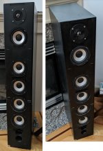
Hi, I'm currently in the process of finishing my new hybrid electrostatic loudspeakers. They have a ripole subwoofer and an electrostatic panel. At the moment, I power them with a MiniDSP 2x4 HD and two seperate, external power amps. But I'm considering a Hypex plate amplifier that integrates two power amps, a power supply and a DSP. Something like the FusionAmp FA122 or FusionAmp FA253.

But before ordering such a device, I hope you could help me answering some questions I have:

* how is the build quality and life expectancy? For instance, I'm currently using a 25 year old Quad 606 MK2 amplifier which serves me well. It feels solid and reliable. Would the Hypex amp be as solid as the Quad? Or will it be a product which needs to be replaced in a few years? For instance, my MiniDSP has power supply issues after only 3 years of use and MiniDSP doesn't cover this in their warranty which makes me feel this hardware is not as reliable and well designed like my old Quad amplifier.

* is the software to program the DSP user friendly? I find the MiniDSP very pleasant to use for instance.

* how will sound quality compare to my old Quad? I personally don't believe in big sound quality differences between amplifiers as long as they can handle the load properly

* how is product support from Hypex?

I hope you can help me with these questions.

Power center

Hello,
I’m selling a Monster power center.
$50 plus shipping
It has one issue, the voltage readout on the front panel will occasionally show low voltage and set an alarm (led on front panel). This has only occurred twice since I’ve owned it. Each time I’ve checked power at source and found no problem. Turn power off and it resets. It hasn’t affected my tube or solid state amps that I can tell. Purchased several years ago for a home theater setup.

Attachments

  • 118B78AA-62B4-49C2-86B0-D5C0B812856A.jpg
    118B78AA-62B4-49C2-86B0-D5C0B812856A.jpg
    701.3 KB · Views: 183
  • 42503D80-869D-4C12-84F4-F83EC6669D39.jpg
    42503D80-869D-4C12-84F4-F83EC6669D39.jpg
    973.2 KB · Views: 177

Ribbon spacing with midrange

I’ve noticed people having larger separation on ribbon tweeters than they “should” be using conventional parameters. I’m building a 3 way with either a tpl150 or a Raal most likely. If the math doesn’t work how is this calculated. My
Midrange is the TD8m and looking to cross 2500 -3000

Do you use c-c or to the edge of the ribbon


The woofer will be th TD15S ,H, or SBP. Haven’t quite nailed that down

diy crossover for hard hitting 80-100hz for Ultimax

diy crossover for hard hitting 80-100hz for Ultimax
I'm looking to diy my first crossover for a 12" Ultimax. I would like to focus on bring out snappy hard hitting bass. I have no idea where to start. I just finished Upgrading the crossovers on my Hivi's so it seems simple enough. I just don't know how to calculate/research components to get the sound I am looking for. Any advice/links would be appreciated. Thanks

Yaqin mc10L

Hi,All, Bought an mc10L, lovely amp but its blown a few of fuses on switch on, the fuses are fast blow 2 amp, was thinking of trying a 2.5 amp fast blow to cure this nuisance fuse blowing but could this possibly damage the circuits, this has only happened on switch on otherwise apart from the power transformer getting a bit on the warm side possibly due due it being 220 volts, I measured our U.K voltage at 242 volts, Any body got any ideas or has come across the same problem would appreciate any help, Thanks Gasman. :smash:

Need solution for powering two TDA 7293 boards

I am a novice with DIY electronics. I ordered two of these boards to make a stereo amplifier. TDA7293 AC 12V 32V 100W Digital Audio Amplifier Single Channel AMP Board -in Integrated Circuits from Electronic Components & Supplies on Aliexpress.com | Alibaba Group

In the photo it shows to connect 32-0-32 dual AC transformer to a board. This would mean I would need two transformers and two mains sockets to power the the combined steroids amplfier right? Is there a way to use a single transformer to get good results or at least so I can use one mains socket to power the finished stereo amplifier?

3 way active system: how to improve midrange?

Hello to everyone!
Some 10 years ago, I have built a three way active system consisting of KEF B139 in sealed cabinet, Visaton W130S in dipole cofiguration, and Monacor DT250 tweeter. Crossover is active, 4th order LR, 250Hz and 2500Hz.
So, what's the problem? Well, actually, there is no problem. Everything sounds great, but I thought of upgrading the mid driver, because I guess there are better sounding midranges, as W130s is pretty cheap (although decent) and it could be weak part of the chain. But, I don't know what to look for. For example, Seas MCA15RCY fits even with dimension perfectly to my cabinets. Will it sound better? Why will it sound better? I was told that if I want better results, I should look to drivers with high Qms, not low (Seas and Visaton are both low on Qms). Generally speaking, what would you look for in midrange speaker, beside frequency response?
Should I leave everything as is, and just enjoy the music?

Thanks in advance!

Backes & Müller Processor Rectifier Board

Dear DIY colleagues,

a few weeks ago I started to designed a few PCBs (Regelplatine) for my Backes & Müller BM18 Processor Generation due to some very foolish recap works from a "BM specialist" (NOT !!!) 😡

I looked at the different PCB Boards and learned a lot about snubbing resistors in the last month. So I decided to redesign the existing rectifier PCB (watch the attached PDF). As you can see the ringing of the transformer is enormous and can be easily reduced with the Quasimodo tutorial :wave2:

I bought the "48 Diode Test whitepaper" from Mark Johnson and decided to exchange the existing (and very bad) GBU8G Rectifier Bridge with four Hexfred Diodes.

My question: Are there any other recommendations or any faults in the PCB design you can identify?

Attachments

FS Bliesma T34B-4

Next up the Bliesma T34B-4 Beryllium 34mm large format tweeters and pains me to sell these. As they are simple top 4 tweeter available today no matter the price range. Nothing produce for mobile audio comes close.

Manufacturer BLIESMA
Tweeter Type Beryllium Dome Tweeter
Cone / Dome Diameter 34mm
Impedance 4 ohms
Power Handling (RMS) 80 W
Frequency Response 1300 – 40000 Hz
Sensitivity 97.5 dB
Features :
• 34mm beryllium dome with variable thickness for ultrasonic first breakup mode
• Extremely low moving mass for better transient response and higher efficiency
• Fully saturated neodymium motor with copper sleeve for low non linear and modulation distortion
• 3mm linear excursion and large vent channel for undistorted low frequency operation
• Narrow surround for less “soft dome” coloration
• Flush mounted surround and rear mounted magnet system for flat frequency response and wide off-axis response
• No ferrofluid for improved dynamics
• Underhung voice coil wound on titanium former
• Flexible and lightweight lead wires made in Denmark
• Thick aluminium powder coated flange
• Aluminium rear chamber with natural wool damping
• Gold plated wire terminals
• Extremely wide recommended frequency range 1.3kHz-40kHz

Asking $600 for these shipped in the U.S. will ship international add $50 U.S. to the price.

Attachments

  • 20200628_085854.jpg
    20200628_085854.jpg
    952 KB · Views: 367
  • 20200628_085922.jpg
    20200628_085922.jpg
    764.7 KB · Views: 365
  • 20200628_085918.jpg
    20200628_085918.jpg
    633.4 KB · Views: 354

Fake or Real Fujitsu Part?

So I was wondering if any of you have come across some of these parts:


Fujitsu: 2sc2526


The parts I have show to be germanium????
On my Atlas DCA55 tester? WTF Over?
Anyone test any of these?


The actual reading from the DCA55 follow:
1) Hfe = 43 Vbe=0.54V DiodeCheck BC= .489 BE= .497
2) Hfe = 40 Vbe=0.54V DiodeCheck BC= .494 BE= .501


Tested the known good silicon device in the amp:
DiodeCheck BC= .570 BE= .573


Are these "NEW" Fujitsu ring emitters that good that the

PN junction is that low?


I've got New close complimentary Toshiba silicons,
1) BC= .570 BE= .570
2) BC= .558 BE+ .562


Tested the known good device in the amp:
BC=.545 BE=.551


Anyone else Test any of these?


Cheers,

Attachments

  • 01.01 2sc2526.jpg
    01.01 2sc2526.jpg
    279.2 KB · Views: 380
  • 01.02 2sc2526.jpg
    01.02 2sc2526.jpg
    374 KB · Views: 350
  • 01.03 Amp Transistors.jpg
    01.03 Amp Transistors.jpg
    308.8 KB · Views: 373
  • 01.04 2sc2526 B-C junction.jpg
    01.04 2sc2526 B-C junction.jpg
    395.1 KB · Views: 344
  • 01.05 2sc2526 B-E junction.jpg
    01.05 2sc2526 B-E junction.jpg
    398.6 KB · Views: 340

Sanken transistors needed....

Anybody know where I can get the following:
2SC4467 and 2SA1694? (complimentary)

bdent seems to have some but they don't seem to be matching Hfe (at least in the photo)

Mary Anns electronics on EBay seems to have them, but I don't know if that is a trustworthy seller and not just selling Chinese knock-offs

Can't seem to find matching pairs in stock anywhere.
They would be used in an old Pioneer Amp.

Th originals were SA1104s and SC2579s but those are marked as obsolete


Also, does STMicroelectronics make good parts?


Thanks!

Sony EV-S2000 Power Supply Oddity

I have a Sony EV-S3000 video Hi8 player on my bench, and could use some help sorting out a power supply issue.

According to the service manual, I should be seeing 3.3V +/- 0.3V at pin 2 of CN2. Instead, I'm measuring -21.1V. Here are my measurements at all five pins of CN2:

Pin 1: -24.4V
Pin 2: -21.1V
Pin 3: Ground
Pin 4: -30.4v (should be -30V +/-3V)
Pin 5: 0.00

I noticed that the difference between Pins 1 and 2 is 3.3V, though not sure what to make of that. Unfortunately, I can't find a schematic for this anywhere, and it wasn't included with my copy of the SM. It does, however, appear that the power supply for the EV-S3000 is very similar. Instead of 3.3V at Pin 2, the SM for the EV-S3000 specifies 5.7V.

Attachments

  • EV-S3000 Power Supply Partial.jpg
    EV-S3000 Power Supply Partial.jpg
    140.6 KB · Views: 186

A Handy Management Module for Ultra Capacitors

here it is, made this for my self and a few audio friends. It is working fine.

NOTE: Has nothing to do with Ian Canada UC Conditioner solutions, which are very good by the way and plug and play. This is more for experimenting or use it as installed solution with large UC banks

It is just a management module to quickly charge a UC bank (up to 20Volt) through an external charger (10 A or so) and than switch back to the audiophile PSU of your choice which is also externally connected. The module will disconnect the charger and de-power its mains. This will save you long waiting time to get your device powered up as would be if you only use the audiophile CPU, which normally has little headroom to charge an large UC (Bank)

The UC Bank should be connected directly at the VB input of the device. Which I believed to be of advantage looking at the concept why a UC helps sound quality (shunt close to device/user) I know some see this critical for safety reasons, so you can still ad a thick 2 pole switch and disconnect the UC bank when not in use. Up to the user of course

It is a general module where the switch voltage can be set by DIP switches. Nice for experiments (like I do now) or in use with other gear (DDDAC 12 volt supply or Clocks/PCs with 15-18 Volt)

As there were concerns about my capabilities designing and building things like this, let me state this: I am not asking anyone to use this or risk their homes. BTW, DIY always carry risk. No need for UCs for that. If I see all that gear with no safety earth, you might dangle dead to your next tube amplifier as well

any way, here is a pic and the circuit:

DIY use only of course 😉


.

Attachments

  • Unbenannt.jpg
    Unbenannt.jpg
    125.2 KB · Views: 366
  • Unbenannt2.PNG
    Unbenannt2.PNG
    110 KB · Views: 365

FS: F5 Turbo v2 50w Class A Amplifer

F5 T v2 for sale.

Highlights
5U case
Dual mono power supply, two toroidal transformers.
264,000 uF reservoir capacitance per channel.
Silver input RCA
Copper output binding posts.

Asking $675. Buyer pays shipping and paypal.
Perfer pickup or meet to deliver amp.

Thanks for looking.

Vince

Attachments

  • f5_tv2_sale_00.jpg
    f5_tv2_sale_00.jpg
    290.9 KB · Views: 501
  • f5_tv2_sale_01.jpg
    f5_tv2_sale_01.jpg
    129.6 KB · Views: 490
  • f5_tv2_sale_02.jpg
    f5_tv2_sale_02.jpg
    273.9 KB · Views: 479
  • f5_tv2_sale_03.jpg
    f5_tv2_sale_03.jpg
    207.2 KB · Views: 494
  • f5_tv2_sale_04.jpg
    f5_tv2_sale_04.jpg
    465.7 KB · Views: 490
  • f5_tv2_sale_06.jpg
    f5_tv2_sale_06.jpg
    396.6 KB · Views: 349
  • f5_tv2_sale_07.jpg
    f5_tv2_sale_07.jpg
    411.3 KB · Views: 266

Are Frugel/Spawn horns for me?

For a while I consider which diy speakers I should build. I think at the moment I can narrow down the requirements list to something which can actually help you experts guiding me to the best optimal solution in my situation. I have to admit that my personal experience with speakers is quite limited. In the picture you can see where I have to locate them (instead of the existing ones).

The space dimensions for each speaker is: Depth 35cm, width 22cc, height 115cm (13, 10, 45 inch).
I looking something of high efficiency which can be used with flea power tube amps
My most favourable music is classic rock. Usually I prefer to listen at relatively low volume

I like rich lows, a lot of presence and extreme detailing level (I know this usually doesn’t go well with low volumes). I appreciate pure analytic sound, as real as possible reproduction with minimal colouring.

Due to their dimensions, charm and potential high efficiency, I put my eye on the Frugel/Spawn horns. The issue is that I have neither experience with FR nor with horns. I’m afraid to be disappointed if they will not have rich lows or missing presence. My time is very limited and therefore I try to find the best match to my compromises.

Will appreciate your advice very much.

Attachments

  • C9E06F5D-869D-4F5B-8DE0-AEF6EF5D6B8B.jpg
    C9E06F5D-869D-4F5B-8DE0-AEF6EF5D6B8B.jpg
    605.8 KB · Views: 334

Components Crossover VS Sound Quality

Hi guys. How is sound quality affected by the components crossover (woofer and tweeter) from a PA? The brands offer lots of different crossover, lets take a look at some.

1. Yamaha DBR10: Crossover in 2.1kHz.
Additional Info Specs
- SPL Peak: 129 dB (325w rms)
- Frequency Range (10dB): 55Hz-20kHz.
- Woofer size: 10 inch.
- Tweeter size: 1 inch.

2. Yamaha Stagepas600i/600BT:
Crossover in 2.8kHz.
Additional Info Specs
- SPL Peak: 129 dB (340w rms)
- Frequency Range (10dB): 55Hz-20kHz.
- Woofer size: 10 inch.
- Tweeter size: 1.4 inch

These speakers (1) and (2) are very similar in a quick look but are different in components.

3. JBL Eon610: Crossover in 1.8kHz
Additional Info Specs
- SPL Peak: 124 dB (500w rms)
- Frequency Range (10dB): 52Hz-20kHz.
- Woofer size: 10 inch.
- Tweeter size: 1 inch

This JBL Eon 610 has less SPL but more watts RMS, the crossover is way lowered to 1.8kHz.

4. JBL PRX 812: Crossover in 1.85kHz.
(This is my favorite one)
Additional Info Specs
- SPL Peak: 135 dB (800w rms)
- Frequency Range (10dB): 44.8Hz-20kHz.
- Woofer size: 12 inch.
- Tweeter size: 1.5 inch

Both JBL speakers reviewed are set up about the same crossover.

Let's see some subwoofers:

1. JBL PRX818XLF: Crossover 80Hz HiPass.
Additional Info Specs
- SPL Peak: 134dB (800w rms)
- Frequency Range (10dB): 30Hz-102Hz.
- Frequency Range (3dB): 35Hz-87Hz.
- Woofer size: 18 inch.

2. JBL SRX818sp crossover: 80Hz, but it plays up to 120Hz in 3dB, so you can set up a crossover up to 120Hz, differently from the above JBL PRX818xlf subwoofer, which is limited to 80Hz crossover, due to frequency range in 3dB goes from 35Hz to 87Hz.
Additional Info Specs
- SPL Peak: 135dB (750w rms)
- Frequency Range (10dB): 29Hz-150Hz.
- Frequency Range (3dB): 35Hz-120Hz.
- Woofer size: 18 inch.

Notice that JBL SRX subwoofer has a lower watts rms but has better SPL and frequency range response, better crossover options for HiPass.

Other subwoofers are eligible to play up to 120Hz, like Yamaha DXS18 and Electrovoice DLX18, but JBL PRX is limited to 87Hz maximum high frequency. This sounds weird to me, because there is no why do it. Jbl Eon618 subwoofer also plays up to 150Hz but JBL PRX does not. It just limit my applications with this subwoofer, I am just unable to apply a 120Hz crossover in JBL PRX818, with my 10 inch speaker because of that, though 80Hz is not bad

ECC88 PreAmp - Questions

A couple of years back, I got bought a PCB from a Chech guy on ebay.

I did get it and all is fine as far as I can tell...but I have a few questions.

I'll post schematic and pics, in the hope that someone will shed some light on those questions.

1. There's a spot for a relay on the board, the model info for that is all well and good, except the relay comes in 5Vdc and a 12Vdc versions.

2. Having listened alot to tube gear, I don't really have much DIY experience in that area....So the question is what value volume attentuator to use?
I have 10K, 100K (quite a few), one 50K (currently in use in a headphone amp) and one regular log potentiometer @ 50K ALPS RK27.

EDIT: nevermind my notes on the schematic, I guessed at the value for the relay as it was the only I found at the time, I now know Farnell carries a 12V version as well.

Attachments

  • ECC88_preamp_schem.jpg
    ECC88_preamp_schem.jpg
    314.6 KB · Views: 604
  • ECC88_preamp_nearly_done_1.JPG
    ECC88_preamp_nearly_done_1.JPG
    585.8 KB · Views: 468
  • ECC88_preamp_nearly_done_2.JPG
    ECC88_preamp_nearly_done_2.JPG
    561 KB · Views: 381
  • ECC88_preamp_nearly_done_3.JPG
    ECC88_preamp_nearly_done_3.JPG
    547.4 KB · Views: 359
  • ECC88_preamp_nearly_done_4.JPG
    ECC88_preamp_nearly_done_4.JPG
    530.4 KB · Views: 429

Help identifying components & possible solution

Hi to all and thanks in advance to those who contribute.

Forgive me as I have to post this fast as we are about to have load shedding shortly, so for now ill keep it short and update with any info i missed when load shedding is over.

There was what looked like a resistor (green body in pic) when measured had a resistance of 564Ohms. a similar "resistor" paralel to it was also discoloured and measured 596Ohms. Both had only the Gold tollerance band left visible.
'
I couldnt find any info on the green body type resistor, only that when i reinserted it into the board it started to get very hot, as did the one parallel to it. The guy at the electronic store recomended i try replace it with a 5W 560Ohm resistor. So i did, but they both still got hot very fast. which tells me something is VERY wrong somewhere.

I am not the best at soldering but i do my best to clean up.

Could the input signal be too high? Sorry, the Amp is a Targa Baby Brat, TG-D-501r.

And what part do those "resistors" Play in the circuit? if someone doesnt mind educating me please, thanks.

PS. thank you Mr. Babin for your help on the Powerbass amp i posted about

Attachments

  • 20210526_top.jpg
    20210526_top.jpg
    782.1 KB · Views: 119
  • 20210526_bottom.jpg
    20210526_bottom.jpg
    910.4 KB · Views: 108
  • 20210526_resistor.jpg
    20210526_resistor.jpg
    277.7 KB · Views: 103
  • image_big_67699203.jpg
    image_big_67699203.jpg
    9.1 KB · Views: 109

Interesting anomaly with room ionizer and OTLs

Can someone explain what's going on here? So far I'm not alarmed. I have a negative ionizer beside my listening position 13ft. away from my Acoustat Servo OTLs. Every once in a while I'll hear a 'snap' out of the ionizer, obviously a discharge of build-up grounding to the fan it's sitting on. However it appears to cause a couple of clicks in one of the amps. They are on separate circuits. It sounds like the relay in the amp is clicking. weird.

Need help with Sansui 4000

Bear with me here as I have tried everything I can think of.
The left channel just crackles with faint music coming thru.
I have replaced the output transistors with ones that tested good on my scope (octopus sweep). Replaced the volume control. replaced ALL the 2SC871 transistors. In both the preamp section and the tone board. I can swap the amp boards back and forth and the problem stays with the left so its not those. I have replaced the electrolytic in the ripple board. and a few of the channel specfic film caps. things that were not unique to the left channel I didn't look at too closely. I get a beatuiful sine wave out of the hi low filter board. But the output transistor gates on the left are an ugly square wave but it stays with the left side if I swap amp boards. I have probably done something else that I am forgetting but this is is drving me nuts.

Attachments

Bass Alignment filter for B&W Matrix 805

I've been trying to find a Bass Alignment filter for my B&W Matrix 805s, but have been unsuccessful. While searching I came across this thread http://www.diyaudio.com/forums/multi-way/35668-anyone-reverse-eng-801-bass-alignment-filter.html. That got me thinking maybe I could build one. I'm not too savy in the engineer department (though I would love to learn), but I can read a schematic and operate a soldering iron, multimeter, and scope. I wanted to see if someone here could help me out on the design of a BAF for my speakers. From what I understand, the BAF is a high pass filter with a bump at the speakers port frequency. I'm thinking a bump around 40 Hz, with a rolloff of the low side, would do the trick Anybody want to help me out with this?

ultra cheap mtm

Just want to report pretty decent ultra cheap midrange (16 ohm) from parts express. So I got two in parallel with cheap tweeter (long time ago sale of 100 in box for like 20 bucks).
I placed no coil on mids (since this is cheap project). Placed just one cap on tweeter. I tried 4.7uF, 6.8uF and 8.2uF. Settled on 6.8.
Results are surprisingly good. Especially directivity.
Cosmetics is still work in progress. Its open baffle, since it will be used on top of the woofers. Measurements are without woofer. Otherwise its flat from 30Hz.

4" Treated Paper Cone Woofer 16 Ohm

Attachments

  • 16ohm1.jpg
    16ohm1.jpg
    507.4 KB · Views: 429
  • 16ohm2.jpg
    16ohm2.jpg
    605.1 KB · Views: 445
  • 16ohm3.jpg
    16ohm3.jpg
    572.8 KB · Views: 433
  • 16ohm4.jpg
    16ohm4.jpg
    591.7 KB · Views: 409
  • 16ohm5.jpg
    16ohm5.jpg
    338.5 KB · Views: 395
  • 16ohm6.jpg
    16ohm6.jpg
    312.4 KB · Views: 218

Shunt-type regulator from Mr. Walt Jung

These days I made a Mr.Walt Jung shunt reg, which I installed in my DAC for power supply for PCM1702. The circuit is from the WaltJung.org web site.Directory listing
For floating power supply from article I need to modify the existing power supply in the DAC so I modified the negative regulator as Improved PN Regs, inserted the NPN and turned the polarity of the diodes and references. For 5V as a reference I used the LM4040. The transistors are TTC004B / KSC1845 for N reg., TTA004B / KSA992 for P reg. and op.amp is AD825 for both. As I have excellent experiences with Walt's regulators for analog circuits, I was interested in how this regulator will behave for digital circuits.
The oscilloscope shows the difference between the old reg and this in noise reduction. There has also been a change of sound, the sound image is much more open with plenty of details and dynamics.
A really good regulator.

Attachments

  • walt shunt reg..jpg
    walt shunt reg..jpg
    413.8 KB · Views: 2,348
  • walt shunt reg. (2).jpg
    walt shunt reg. (2).jpg
    331.1 KB · Views: 1,726
  • walt shunt reg. (3).jpg
    walt shunt reg. (3).jpg
    219.3 KB · Views: 2,532
  • UnivReg_122714.pdf
    UnivReg_122714.pdf
    303.9 KB · Views: 726
  • reg. neg.png
    reg. neg.png
    41.9 KB · Views: 2,588

yet another hum/buzz problem?

Hi everyone!
I just finished another project which is made of:
DC-blocker + soft start
toroidal transformer
Bridge rectifier
preamp
source selector + remote control module
BT_DAC
some VU meters
speaker protection
and of course power amps

Below two photos from early build stage to relate to:
An externally hosted image should be here but it was not working when we last tested it.

An externally hosted image should be here but it was not working when we last tested it.


Everything works flawlessly while this setup is powered in series with a bulb. Minimal hiss. No buzz/hum. But when I connect it to the same wall socket without bulb in series, I start to hear buzz from speakers. Also, transformer starts buzzing. When I remove top cover it is slightly less hearable, but with a cover screwed on it's beyond being acceptable.
Does any one have any idea what can cause such a behaviour?
I am aware that above setup is not described in much detail, but having in mind that all works well with the bulb it might be something trivial. However, if more details are needed - please do let me know and I'll update you with more data.


Thanks!

Low frequency modulation distortion in foil resistors

Did anybody notice the comments in the latest Audio Precision newsletter about metal foil resistors having low frequency modulation distortion? They suggested that conventional metal films are better choices for audio. IMO, that should raise some high end eyebrows.

Now, my question is what's the test setup to reveal this, particularly if one doesn't have the $$ for an AP setup?

AP Powerpoint article

toroidal transformer mounting, insulated?

Hi,

I'm working on a tube pre amp and it is ready for test and adjustment. However everytime i switch on the power the fuse blows.

I triple checked wiring etc, tested with all secondary's disconnected but everytime the fuse goes blown. When wired up out of the case and out of circuit no prob and voltages at ac are ok. When mounted inside the chassis with nothing connected the fuse blows.

I know the center mounting bolt and thus the mounting plates (toroidal) is connecting to earth/ ground but would that be enough to blow the fuse? if so, is it safe to just isolate that center bolt and be done? ie no short winding to the trannie?

I've tried and used the mounting materials provided and have not seen this behaviour from this supplier (Amplimo, 4n183) before on other trannie types from this supplier.

Should i just isolate the center bolt and thus the mounting structure, from earth and be done with it or do I need to do something extra?

Just checking, normally i isolate the center bolt and one of the mounting plates thus preventing the short. but I have not experienced fuses blowing when not doing this before.

thanks for answers in advance.

Kind regards,
Joris

Op-amp observation and question

Hi all,

Hope this is the proper forum for this topic - mods please move it if it's in the wrong spot.

OK, first off I'm not one of "those" people who claim to be able to hear differences in various alloys of speaker wire or differences in capacitor brands, etc...

Now, to the point: I've got a little Class D audio amplifier with Sony SSCS5 speakers for playing PC sound output. The amplifier has two 8 pin DIP sockets so that the pre-amp op-amps can be "upgraded". The amp came with generic NE5532 parts... sounded fine.

Although I don't believe in "audiophile" things like "premium speaker wire" or $150.00 "speaker fuses" or "magic infused capacitors", etc, I thought I would try a few different op-amps and see how they "sounded". I tried TL072, TL082, 4558, LM358 and OPA2134. To compare them, I left a 5532 in one channel and put the test op-amp in the other channel. I connected a signal to one side, then the other so that if there were any difference, I should hear it.

As I expected, they all sounded the same. After all, it's just an op-amp. Signal in, signal out.

Then, I read about the OPA1656 and thought "why not?". Well, OMG how to describe it? The resulting audio seemed a lot "better". More bass, and it sounded "tighter" (like the difference between a cheap ported speaker and a sealed one). The high end was, for lack of a better word, "brilliant". Even the midrange was a lot "cleaner". (by the way, all the chips I tested came from Digi-Key, not cheap Chinese knockoffs).

OK, so now I am totally confused. It's just an op-amp. Signal in, signal out. HOW ON EARTH can the OPA1656 sound SO much better? Is the 1656 "better", or is it "right" and the other parts "insufficient"?

Another observation: I built a little stereo signal summer which is a pair of simple unity gain inverting amplifiers (+/- 9 volt power, 47k feedback and 47k input, non-inverting input grounded, dc coupled, 3 inputs per channel). It works fine and with this circuit, ALL op-amps sound the same. There is no difference between the NE5532 or the OPA1656 or any other one.

So now I'm more confused. Why the big difference in my amplifier and NO difference in the summing circuit?I

The audio amp, by the way, is a AIYAMA A04 which had a TPA3251 power stage, one NE5532 preamp per channel, and it's running on 32 volts. I also have a AIYIMA A07 which is basically the same as the -04, but it uses a TPA3255 power stage instead of the 3251. This one also works dramatically better with the OPA1656 preamp.

Any explanations for this strange (to me) behavior?

Thanks!

Designing crossover for good power response

I'm modifying a pair of ATC SCM20 Pro PSL Mk2 monitors - making them active and lowering the crossover point as low as realistically possible. The included crossover point is advertised to be 2.1khz, but 1.975khz seems to be what it actually is.

I did a frequency sweep of the woofer at 0 and 45 degrees. The woofer's -3db point at 45 degrees is 2150hz. Ignoring (for now) the potential for harmonic distortion from the tweeter, and aiming for a design with the best on axis frequency response and also the widest horizontal dispersion, what should the crossover point be? With the 10 inch baffle, the tweeter's on axis response will experience a suckout starting at ~1400hz, increasing in severity until it's down 6db at ~700hz (baffle step), so it would seem like a 4th order at 1.6-1.7khz would be needed to have the signal down 6-8db by the beginning of the suckout, but I'm probably making a new box with a wider baffle to move the suckout to 1000hz - 1.2-1.4khz is my target range (the bigger box will also allow for a lower q alignment (sealed design).
I know that harmonic distortion can be an issue for some tweeters, but it very likely won't be for this tweeter - I'll be doing tests later to confirm the lowest viable crossover frequency at the power levels I'll be running. Because the tweeter is essentially omnidirectional at any considered crossover frequency, it's just the woofer that needs attention.

For an excellent power response and the associated optimal horizontal dispersion, how many db down at 90 degrees can the driver doing the lower frequencies be? 3db? 6db?

If a driver is 3db down at 45 degrees, can you halve the frequency and extrapolate that the -3db point then doubled to 90 degrees? (This woofer at 1075hz???)

Is there a rule for how many db down at 90 degrees at crossover a driver can be for a speaker with good power response?

I'll be considering this frequency along with others yet to be determined/measured/calculated for the crossover, picking the lowest that allows for widest flattest frequency response, with acceptable distortion

VisatonLTS50coating a fullrange driver

Visaton LTS50 is a coating compound for loudspeaker cones (paper). To test if iit does anything I coated some vintage oval fullrange drivers 6" by 4"

Frequency response (Omnimic at 10 cm on axis) with one of the drivers set -5dB for clarity
Uncoated, one coat of front, one coat of front and one of the back side of the membrane. Not much going on.
LTS50.jpg


I then looked at the time domain
Uncoated
Front one coat
Front one coat and back one coat

2-uncoatedES.jpg

Note past 6 cycles in two ranges

2-FcoatES.jpg

Past 6 cycles in one range after front coating

2-FBcoatES.jpg

Not past 6 cycles with both front and back coating

1-uncoatedES.jpg

Up to 10 cycles in two ranges uncoated

1-FcoatES.jpg

That thing at 5-6 kHz dropped from 11 cycles to 8 after front coating

1-FBcoatES.jpg

A further reduction

It does look like an improvement😀
  • Like
Reactions: maty tinman

DC "Cable Clamp" name

So this has driven me nuts scouring around trying to find and figured you guys of anyone should know the answer.

I see these on all kinds of audio gear but don't know the proper name for them. They're usually mounted right next to the DC jack to prevent accidental disconnection. In Radial's Backtrack manual it just says "Connection for the
included power supply with handy cable clamp to prevent accidental disconnection."
But searching "Cable clamp" brings up nothing but products for much larger cables with a totally different purpose.

EXTC-SA-back-768x356.jpg


Thanks!

Paragon System-E PS schematic needed

Does anyone have a schematic for this power supply?

Failing that, can someone fill me in on the specs of this capacitor:

Sprague 36DX 540-450 WVDC 7452L

google reveals only that it is discontinued, but no specs ie, I have no clue of it's value.

Similarly, there is a quad cap in the unit that is unmarked.

The general layout of the power supply appears to be a CRCRC filter. (C1, R1, C2, R2, C3), with the two C2 R2 C3 sections attached to the initial CR in parallel.

C1 is the Sprague, the quad cap holds the other 4 caps used in the parallel CRC sections.

Each of the of the C2R2C3 sections powers one channel.

The voltages are approx. V(c1) 420, V(c2) 380, v(c3) 290.

the transformer is a 300V AC, with full wave bridge.

The PS powers a total of 6 12ax7's, 3 per channel. According to the sylvania sheet, the Plate resistance of a 12ax7 at 250V is 62.5K Ohms. If memory serves, R1 looks like 30K, R2 6.8K.

Problem is, I can't model this using the duncan amp simulator due to the parallel CRC section.

Any idea on what the quad is or better yet, SHOULD be?

Thanks for any help...

CSR8645 Bluetooth 4.0 AAC APT-X Module / Baseboard

To my knowledge and what i have had read here in the past, there's always some trouble with those "chinese" bluetooth modules. (Noise, Performance, Range, etc.)

So i'll make "my own" baseboard for the CSR8645 modules.

The modules i use are available here:

2015 New CSR8645 4.0 Low Power Consumption Bluetooth Stereo Audio Module Supports APTx-in Other Electronic Components from Electronic Components & Supplies on Aliexpress.com | Alibaba Group

The board will nothing to fancy.

- dual power input (USB / DC-IN 6-15V)
- differential output or diff2se stage
- MKS/MKT coupling caps for those who need.
- break-away with buttons
- all GPIO on pinheader
- SPI interface (maybe with 3V3 levelshifter)
- output on pinheader or 3.5mm jack
- 3.5mm input jack with "priority" routing
- 50x50mm pcb space using standard components
- easy to solder due to 0603 parts (some 0402 ferrites at the USB line)

Well, thats it. I want to use this for small class-d-amps (TPA3116/3118/3251/3250 etc.)

Actually arranging parts..

attachment.php

Attachments

  • CSR8645_Module.jpg
    CSR8645_Module.jpg
    99.9 KB · Views: 8,452

David B. Weems

Just received a heads-up from Dave Planet10 that David Weems has passed away:

David B. Weems - 1922-2021 - A Tribute | audioXpress

Very sorry he didn't make it to a century, but he'll be kindly remembered by his family and the many thousands of audio, history and goat-keeping fans for his books, articles and by all accounts, by simply being a really decent person. Some of his work on quarter-wave pipes helped foster my interest in the field, and much of his work had a strong 'practical' angle, being written in a way that was accessible and encouraging to people just starting out in the hobby, who may not have otherwise known where to begin.

Thank you, David. God speed, and enjoy the music.

2M3 - SE Mosfet Amp

I designed this to replace my dead 2a3 SET amp. @6w into 4/8 ohm load. FFT is 1v into 7 ohm load using a 16bit Pico Scope. Speakers shown are 97db & 8 ohms. Exicon Lateral Mosfets.

Dwight

Attachments

  • E8F6B7C9-6AFA-4664-BC4D-15526F0DFF3B.jpeg
    E8F6B7C9-6AFA-4664-BC4D-15526F0DFF3B.jpeg
    48.1 KB · Views: 361
  • 1DAE6214-7E42-4CAD-BA55-513BC9D098C7.jpg
    1DAE6214-7E42-4CAD-BA55-513BC9D098C7.jpg
    1.1 MB · Views: 365
  • 62D0A1E2-D824-462C-86E8-FD36A0288F7E.jpg
    62D0A1E2-D824-462C-86E8-FD36A0288F7E.jpg
    1 MB · Views: 344
  • 1A6E518B-9CBF-442C-99A2-F93499639987.jpeg
    1A6E518B-9CBF-442C-99A2-F93499639987.jpeg
    289.4 KB · Views: 316
  • 027FB73E-E40B-4D2D-A0F7-32BF88DBBCB6.jpg
    027FB73E-E40B-4D2D-A0F7-32BF88DBBCB6.jpg
    796.1 KB · Views: 316
  • DCA7DEF7-58F2-448B-8B1B-03EFBB78AC38.jpg
    DCA7DEF7-58F2-448B-8B1B-03EFBB78AC38.jpg
    523.3 KB · Views: 178
  • AC036CAE-3433-4930-BC91-DCA3AF95D5E3.jpg
    AC036CAE-3433-4930-BC91-DCA3AF95D5E3.jpg
    997.2 KB · Views: 202

National Matsushita 7dj8-Pcc88 Matched pair

For sale matched pair of superb sounding tubes that you can use in place of Ecc88 or 6dj8.I buy this about two years ago from upscale audio when they become this in stock. This tubes are new and Nos! I Pay for this pair 100usd+30usd shipping+25usd taxes in europe.Tubes are verry low nois and microphony-platinum grade! I would sell this for 60 euro plus caa. 7,90euro shipping inside EU. Payment plese with paypal!

Attachments

  • IMG_20210522_182517.jpg
    IMG_20210522_182517.jpg
    505.4 KB · Views: 182
  • IMG_20210522_182523.jpg
    IMG_20210522_182523.jpg
    499.7 KB · Views: 175
  • IMG_20210522_182538.jpg
    IMG_20210522_182538.jpg
    479 KB · Views: 168

A constant-Ic β-tester: β-Master 🌈

This tester was developed as a spinoff from this thread:
https://www.diyaudio.com/forums/sol...collector-current-hfe-tester-transistors.html

The circuit proposed proved too complex for the OP, but I decided to bring it to completion anyway: it is probably a useful piece of kit for many DIYers.

The complexity, especially in its finished form, might look daunting, but that's kind of inevitable with this type of instrument: many parameters need to be made variable, and being a transistor tester, it has to accommodate both sexes, which brings another layer of complexity.

That said, the complexity is relative, and no expensive component is required.

It can be built as a naked board, with an external supply and multimeters as indicators, or as a complete, self-contained instrument (or anything in-between).

It does have some attractive features: it covers most of the needs for DIY use, with an Ic range of ~150µA to 1.5A, a Vce of 0 to 10V, requires a single unipolar supply, and the switches for the range and polarity are ordinary DPDT types (one has a center OFF).

A constant Ic tester is very convenient compared to alternatives improvised with supplies for example: comparisons are immediate and straightforward.
The direct-reading is also very convenient.

I didn't build and test a complete instrument: I just breadboarded the functional core for NPN (which operated as expected), and I also tested critical sections, like the polarity handling meaning the project is relatively safe.

The complete instrument has been tested in sim, and is functional (I include the .asc).
Note that this is a DIY-grade instrument, not a lab reference, but with care in construction and a good calibration, it is OK for a +/-1% accuracy, which is ample for a parameter like β.
Comparisons can be made with a greater accuracy.

This is the circuit:

attachment.php


And a sim showing the measured value against the actual value (β+1 because what is actually measured is the ratio of Ie to Ib, not Ic/Ib):

attachment.php

Attachments

  • Betamaster0.png
    Betamaster0.png
    67.6 KB · Views: 1,058
  • Betamaster1.png
    Betamaster1.png
    48.1 KB · Views: 1,078
  • Betamg.asc
    Betamg.asc
    34.3 KB · Views: 97

HYPEX Ncore NC252 Amplifier : free shipment to Europe

Hi,

I sell my Hypex Ncore NC252 brand new.
Made with great components and with AC Audio Grade filter.

420 euros shipped to Europe Only


The NC252MP has been reviewed here :

Review and Measurements of IOM NCore Pro PWR Amp | Audio Science Review (ASR) Forum

2x150W / 8R
Low THD
Nice amplifier for all day use

- NC252MP
- Full All Case
- Audio Grade AC filter
- Sommer Cables Germany
- Push Banana Plug
- Full balanced XLR inputs


New to DIY amplifier building

I must confess that I'm very new to DIY amplifier building. I'm more familiar with speaker building though.

I'm interested to build a Class-D amplifier. Yet, I don't know how to start it.

I'd like to ask guru in this forum that is there any cookbook about Class-D amplifier building available, as the speaker building has such as Vance Dickason's?

I've already googled it. But, only I found was apart from Class-D, mostly Class-A and AB.

Neurochrome 686 Brand New Build

I was intrigued by reports of how good these Neurochrome modules are and also had a few requests to build some, so I thought it was time to try some out and evaluate the amps. The build was fairly straightforward and I used a chassis from Modushop who supply most of my cases. Tom the designer provides drawings for this chassis and suggests the large chassis shown in the accompanying photo.

The amp has a slow start module, and includes a sophisticated output protection system to protect your speakers. In practice, it turns on and off without a thump or buzz, with a small click as the relay clicks over. Construction is fully dual mono, and fully balanced with inputs by XLR. I’ve fed the amp with single ended source from my own brand ESS9038pro valve DAC, and also used a fully balanced source too. There's no great difference in sound quality between the two.

Residual background noise is effectively inaudible, even with my 96db sensitive JBLs, and sensitivity standard at 2v.

I’ve run the amp now for some 24 hours so it’s partially run in. Overall, I’m very impressed. I should confess here I’m a valve man through and through, with 845, 805 and KT120 monoblocks in the house and studio. But I do get quite a lot of high end
Solid state gear through my workshop and also tried the Nord Class D amps a couple of years’ ago and have built Hypex-based amps for clients, but both of the latter left me cold.

This amp on the other hand is very musical. It’s neutral and revealing, but without robbing music of its soul. Bass is powerful and tuneful, and soundstage wide and deep. Higher frequencies are convincing, unlike IMO Class D amps that I’ve heard. For anyone who has an aversion to valves, young children or mischievous pets, or in need of 200 watts into 8 ohms, 360 into 4ohms, this could be the amp for you. I would rate it above the large Krell or Mark Levinson amps if you want a comparison. Tom the designer makes a lot of the need for a lot of heatsinking but with my 90db and 96db sensitive speakers the heatsinks hardly rise above room temperature.

£2,650

RCA switch grounding

I am planning on making a switch box with 1 RCA in and 2 RCA out. The purpose is to connect one preamp to 2 power amps. I can buy one like in the photo but would rather build it and I already have all of the parts.

Question:
Should I only switch the + signal and just connect all of the grounds together or switch both the + signal and grounds for each? Or wire it differently?

This is what I am talking about:
attachment.php


Thanks

Attachments

  • RCA switch.jpeg
    RCA switch.jpeg
    30 KB · Views: 1,212

Dual 701 and tonearm mods

It took me some time to get the courage to work on my Dual 701.I did some work on the electronic section replacing the capacitors and the discrete series regulator with a MC7815CT which also trips at 800mA so current protection is now included, just in case.... for those rare germanium transistors.
But what really drained me was to rework with copper and lead its tonearm counterweight cause i broke the original one out of curiosity just to see what dual resonant counterweight means...and it led me to the actual counterweight system which is develloped more on the horisontal being also heavier and closer to the pivot allowing both fixed and fine tuning weights to be damped.I actually cut by 2/3rd the internal brass rod attaching te counterweight to the toneram to make the tonearm itself as light as posible.More work on that later as i don't really like heavy tonearms and preffer to get the damping trough different methods .I also added my new semiautomatic 12 inch tonearm that has also end of record electric sensor and lift and conceived a leaf spring based system additional to its own spring damping system.Thus i removed the 701 original wooden enclosure and kept the internal platic support cut to a minimum and adding some more silicon rubber damping basically creating two completely separate damping systems that can also accomodate my other Dual 1219 turntable as 1219 and 701 need identical spring fixture .More work and photos later this year.

Attachments

  • IMG_5510.jpg
    IMG_5510.jpg
    835 KB · Views: 1,036
  • IMG_5511.jpg
    IMG_5511.jpg
    819.1 KB · Views: 866
  • IMG_5515.jpg
    IMG_5515.jpg
    866.8 KB · Views: 692
  • IMG_5516.jpg
    IMG_5516.jpg
    865.4 KB · Views: 690
  • IMG_5485.jpg
    IMG_5485.jpg
    976 KB · Views: 768
  • IMG_5490.jpg
    IMG_5490.jpg
    787 KB · Views: 653
  • IMG_5492.jpg
    IMG_5492.jpg
    900.4 KB · Views: 646
  • IMG_5496.jpg
    IMG_5496.jpg
    900.9 KB · Views: 615
  • IMG_5499.jpg
    IMG_5499.jpg
    957.3 KB · Views: 584
  • IMG_5502.jpg
    IMG_5502.jpg
    891.7 KB · Views: 631

Advice on a kit?

Hello One and All,

I’m N3rd and this is my first post.

First let me say that I’m blown away by some of the amazing projects being shown here, I wish I had half as much talent!

Like everyone, I like as much bang for my buck as I can get. And, as I’m sure you’re all aware, excellent HiFi can cost a lot.

So, I’ve gotten it into my head that the most economical way to get great speakers is to buy a kit.

However, the problem with kits is that there are far fewer reviews to help sort the excellent from the good from the OK etc.

The kit I’m interested in is the Visaton MONITOR 890 MK III.
Link:
Visaton MONITOR 890 MK III - price per pair. – Impact Audio

Now, nearly £4000 on a kit is a lot of money, so may I ask if anyone has had any experience of how these speakers sound?

I know it’s a personal thing, but if anyone could give me some clue about how they sound, and if you heard better, what that was?

Quite a big ask, I know but info on kit quality seems a bit thin on the ground.

Thanks in advance to anyone taking the time to read and comment.

N3rd.

Looking for advice on reusing midwoofers and tweeter for active speaker

I wanted to learn more about DSPs and active speakers. So I got myself an ADAU1452 board and a 6 channels TPA3116 amplifier, as a starting point. And the DSP programming part is pretty well understood at this point

Instead of buying a few random speakers online, I found a Craigslist deal and got a couple of DIY tower speakers with one tweteer and 5 midwoofers. 12 individual speakers to play with for the cost of a cheap lunch for two.

The current speakers are in a 3/4" MDF box, 8"x15"x44", no bracing, and lots of fiberglass batting insulation inside (yuck, hate fiberglass). I listened to the speakers, and pretty much hated the sound (weirdly, almost no mids, and very hot high frequencies. Granted it was a quick test and the speakers were very poorly positioned). The design and build seems very competent, and there is a pretty beefy crossover, which seems well built; the midwoofer closer to the tweeter is in its own separate enclosure, also filled with fiberglass, so I can only assume that the builder actually wanted that sound signature. To each its own, I guess. Pretty sure that the boxes will be given away, too big for my rooms anyway and even if well built, would require too much work refinishing them for any type of WAF.

So now I find myself with 10 MCM 55-1870 midwoofers (specs enclosed) and two Dynavox 53-570 tweeters (no real specs, just a frequency range and sensitivity info). Very little information on both, especially the tweeter. From what I could find, those were semi-decently regarded cheap speakers, especially the midwoofers, and the tweeter is known to have higher sensitivity at higher frequencies, resulting in less-than-linear graph. But since I plan to use a DSP and dedicated amplifier for each channel, I can correct that.

Let me say upfront that I have no expectations to end up with a good speaker. My goal is to learn, and learn as cheaply as I can, reserving the budget for better components once I know enough

At the moment the speakers I listen to the most are a pair of Paul Carmody Speedsters I built from a kit. Love those speakers, and one day I will experiment more with ribbon tweeters

I was planning to build a 3-way active speaker, with a tweeter, a midwoofer in a standalone enclosure and 2 (or 4) midwoofers as bass, with a port to help reinforce the bass. It's unclear to me if crossing over the single midwoofer differently than the 2 or 4 "woofers" will help improve the sound vs using all 5 midwoofers with similar filters. That's part of what I want to see first hand and learn. I listen mostly at low volume, and relatively close by in smaller rooms. I'm not looking for a visceral bass (I also live in an apartment, and powerful bass tends to p*** off neighbors very quickly)

But given my listening habits, I was thinking also about an open baffle design (which, incidentally, it's easier with the limited tools I have in the apartment. I used to have a decent workshop, but not anymore). Clearly with the puny midwoofers I have, a true open baffle will have no bass, so maybe an open baffle for the tweeter and one midwoofer, and the other 2 or 4 woofers in an ported enclosure.

Any suggestions? What would you do with the random set of components I have? What is worth exploring, to learn more about active speakers? I don't have enough for a linear array, even if I saw a design using 8 of my same woofers Kevin's Straight 8 Speakers (but I have no intention to buy more of those)

I think I can tame the tweeter to sound close to what I like. But maybe I should consider a real woofer (no bigger than 6-8") to complement what I have. If so, suggestions for a cheap/honest woofer to consider are welcome

P.S. If anyone local to Seattle is interested in the boxes, send me a PM. The box is pretty well done and with a different baffle can be used for quite a lot of designs. I just don't have the space to store it for the future

Attachments

  • Tower speaker.jpg
    Tower speaker.jpg
    157.2 KB · Views: 160
  • 53-570 tweeter.PNG
    53-570 tweeter.PNG
    227.8 KB · Views: 157
  • MCM 55-1870.pdf
    MCM 55-1870.pdf
    2 MB · Views: 86

EAR834 small hum problem

Hi tube friends. I have question about how to tackle small hum problem in aer834 clone. Its ebay kit, works great, sounds sweet, but it has ~12 mV hum, looks like 60hz on output. I use 12 Vdc on heaters, well filtered. I use ~200 Vdc to power it, two sets of filters, each channel separate. When i touch the grouning connector, the one you use to ground the wire from turntable, hum is lower, but still there. I am only testing it with cheap sony ttable, no separate ground wire. Preamp is not in box, just on the floor. What should i try to eliminate hum?

Btw i built shure m-65 tube riaa preamp, ebay kit, and it works great, sounds great, no hiss, no hum, no box, just testing. No hum whatsoever.

Thank's for suggestions.

JLH "Liniac" RIAA

Hello everyone!

I intend to make a correction RIAA preamp transistor for a friend but I would like to have your opinion on the following diagram.
I also have a question about the capacitor 250uF is it related to the RIAA is correct or that a 220uF capacitor is suitable?
The link to the original scheme is on the website of Paul Kemble (A Paul Kemble web page - John Linsley Hood preamp designs.).

Thank you!

Attachments

  • Liniac.png
    Liniac.png
    7 KB · Views: 1,627
  • RIAA.png
    RIAA.png
    42.2 KB · Views: 1,602

Driving RGB LED's

Maybe not the right place here on an audio forum but in "Everything Else" we can post other things .
I've been looking for a way to drive RGB LED's so that with like up/down buttons I can fluently change the colours.
Looking at the IC's on Mouser or Texas Inst sites , I can't see the trees through the forest. So many LED driver IC's but not what I am looking for.

Closest I've come to designing it myself is an up/down counter that drives the addresses of an EPROM , and its output drives the PWM of the 3 LED colours.
Problem with this is progamming the EPROM.
Even with 5 bit resolution/LED , that's near 100.000 adresses of a 1Mbit EPROM ... by hand .
There must be an easier way but without an uP using only custom IC's with logic and EPROMs.
How does Philips Hue do it ? How would you do it ?

NC400 general input Q's

Hi -
(OK - covered elsewhere, but all a bit disparate/technical for novice - looking for summary of input Q's - therefore hope this is relevant/helpful to others)

I am driving NC 400 via balanced out from DAC.

1; NC400 passive pot wiring; was recommended as in fig A - have been running fine for some years - though would fig B be better?
(I did run S.E. for a while, and I think A is Hypex's recommendation for this...)

2; I'm considering the addition of an external buffer (n.b. have no long runs...) - some say; more dynamics, a bit more warmth, though I understand this is less if at all applicable to NC400 as it has built in input buffer stage. A simple 'KISS' ('keep it simple, stupid'!) or 'ACT' (active!) opinion without the trouble of huge technical explanation would be hugely appreciated.

I understand my Q's are painfully basic, thank you for perseverance!

Attachments

  • P1020651.jpg
    P1020651.jpg
    141 KB · Views: 162

Transformer orientation

Hi, I asked this question in another thread, but perhaps here is the right place to ask.
I just copy-paste it, hope this is ok.

"After a very long time on a MDF board my D3 will receive a case. I bought a Linn Intersekt case for very little money and now mod it to my needs.
My question is : Which way to mount the PSUs would you prefer and why ? Is there a difference if the transformers are side by side, facing away from each other or even one on the floor one on the wall ? Which would make sense ? Here are my possibilities."

Perhaps i should have asked in the PSUs section first.

Attachments

  • LINN01.jpg
    LINN01.jpg
    563.2 KB · Views: 161
  • LINNPSUs.jpg
    LINNPSUs.jpg
    775.8 KB · Views: 162

Improving the hollow plastic phase plug in Seas driver

I've just bought a pair of Seas CA18RNX/P drivers, and the phase plugs are a hollow moulded plastic item. They sound hollow when tapped and fall off when twisted. So now curiosity has got the better of them, I could fill the hollow with resin or silicone etc to fill and dampen them. Or go full nut job and machine a new pair of plugs from aluminium or copper and fit them with a bolt through the 'pole vent'.

What would be the better option? Is there an issue with copper or aluminium above the gap only, forming an eddy current shorting ring for the positive stroke only?

OR should I just fill them with 2 part silicone to deaden them and stick them back in with some epoxy?

thanks

Tango FX-40-5 Output Transformers (Pair) 5k

These are used but in superb condition. Ideal for 45, 2a3 or 300b push-pull. For inspiration check here: "Fatboy" 300B Push-Pull Amp

I am looking for 450 swiss francs for the pair plus shipping.

Shipping to Europe and UK is 50 swiss franks
Shipping to USA is 75 swiss francs
Shipping to Japan and Australia is 90 swiss francs

These are original Hirata Tango transformers. Secondary connection for 4, 8 and 16 ohm.

I really hate to part with them, but need to reduce. PM me if you have interest. I will post photos soon.

Ian

Lii Audio W-15 in an aperiodic enclosure?

Given the big Lii Audio driver is of a high Qtc of 0.79...and has a 8+mm of Xmax...and a very uncontrolled Qms value...The driver sims as wanting to be sealed, has a mid-twenties F3...the enclosure size is rather impractical....has anyone tried an aperiodic enclosure?
No, my cheap open-baffle days are long gone, and I "don't believe" the hype of baffle-less proponents.
The actual mathematical science of Aperiodics has not been put to paper & calculator as of yet.
Thoughts?


-------------------------------------------------------------------------Rick....

Designs similar to the BD-Pipe

Back in the mid-Naughties, I had 4 of the Radio Shack 40-1197 drivers, and spent many a happy hour checking out speakers that used them. The BD-Pipe always appealed to me. Folded pipe, with a 45-degree rear facing driver for added spatial neat-o-ness. But I never built anything.

So, now, a decade, a divorce, and a lot of livin' later, I am once again seated in front of a computer, looking at small full-range speaker designs. And I still like the ideas in the BD-Pipe design.

So, are there current designs that are similar? 4" - 4.5" FR drivers, compact tower, easy build, easy load for low-powered amplification, and with that angled, (or upward-facing,) psuedo-omni driver. Corner placement is a must in my tiny, weirdly shaped living room. and it's an upstairs apartment in an old house, so lotsa bass isn't a goal.

--Shannon
Projects by fanatics, for fanatics
Get answers and advice for everyone wanting to learn the art of audio.
Join the Community
507,730
Members
7,886,115
Messages

Filter

Forum Statistics

Threads
406,133
Messages
7,886,115
Members
507,730
Latest member
plumb stupid