FS: Frugel-Horn Mk3 Pro build, incl outriggers and speaker terminals NEW

Selling a pair of professionally CNC'ed Frugal Horn FH3's. The bezel is machined to accept the Fostex FE126En drivers. Includes outriggers, spikes and speaker terminals.
Built from high quality marine grade Baltic birch.
Asking $350. Shipped at buyers expense, local pickup in DFW or I can deliver to Houston next week.


AMP Setup Recommendation

New to Amp boards here and need some suggestions and help!

Plan on building a 2.1 speaker setup, and have got some requirements on mind for the amp:

1- has > 70w x 2 channels
2- has >= 100w subwoofer channel
3- has Bluetooth module

Found https://www.amazon.com/AOSHIKE-DC12V-24V-Subwoofer-Amplifier-Bluetooth/dp/B07BKYL3GC/ref=sr_1_5?dchild=1&keywords=tpa3116+amp&qid=1629042633&sr=8-5 which satisfies 2,3 but its only 50w per channel.

Couldn't find any "Cheap" boards that satisfy all 3 requirements that I have.
Can I use one of this in conjunction with one of that for the ultimate 2x100 + 100w? How would I go about connection both amps to work as one single unit?

Thanks in advance!

horn vs xover issue

Hello good people,

I'm relatively inexperienced at this stuff and a little confused by what i'm running up against. My buddy gave me a JBL floor monitor which was not working. I pulled it apart, the woofer worked fine if i used a tone generator on it, the horn seemed to work fine similarly, so i assumed the two way crossover had an issue. I replaced it with one from amazon, and had the same issue, but i could hear that there was audio coming down that line with an induction wand. I tried several other speakers that should have been able to replicate high end frequencies and got nothing. I then took the leads from the x-over to the woofer and put them to the horn and it made high end noise. At this point i assumed i got a DOA crossover and had amazon replace it. New crossover is having the same issue. If i run full range to the horn, it functions ( i know not to leave it like that) Anyone know what might be going on here?

I did look through the forums for a similar issue, but didn't find one. Apologies if i missed it.

Thanks
telfer

Speaker: JBL JRX100
horn: JBL2412h-1
Woofer: JBL M112-8 (8 Ohms)
original crossover jrx112M
new crossover(s) EMB CX-5

Valve Inconsistancy....

Hi All,

I own a Fender Pro Junior which I have owned for about 5 years. Shortly after purchase, I renewed all the electrolytic capacitors and replaced all the signal resistors with metal film. I also redressed the wiring routing etc. It's PCB shows 2005 so would think it is a series 2. It has always been excellent and has always been without hum and noise (no i/p, no volume) except for a very small hiss if putting an ear to the speaker.

Recently I had the V1 go very microphonic so replaced it with the same make and type (Philips NOS 5751) as I originally bought them as a pair. I was very surprised to find that the replacement valve produced quite a noticable 50Hz hum when fitted. I then visited my valve box and tried 4 different makes of 12AX7's. All but one gave quite a noticable hum at different levels. The one that didn't was a Groove Tube 12AX7 which was virtually silent. Not to be put off I then purchased 2 x JJ 5751 Gold Pin valves from a very reputable dealer as the valves were supposed to have quite a good review. Hoping for great things I tried both in the Amplifier. You can imagine my disappointment when they both had considerable hum, with one a lot worse than the other. I have now re-fitted the Groove Tube 12AX7 and now everything is good.

Question: Are all valves we buy now so unpredictable in their performance? I am now at a loss, as I could buy some more Groove Tube 12AX7's and find they are hummy too.
Roger

Complete FC100 Kit

Hi,

I have a complete FC100 Kit for sale. I have participated in the FC100 group buy but sadly haven't had the time to finish it. The amplifier boards are completely assembled and tested working. The only missing part is an enclosure for this brilliant amp.

https://www.diyaudio.com/forums/group-buys/293550-roenders-fc-100-buy.html

My offer consists of the following items:
- 2x Fully assembled FC100 Boards with matched transistors (see the thread above)
- 2x Fully assembled Shunt power supply for the preamp stage
- 1x Fully assembled soft power on PCB
- 1x 1x230V/4x34V toroidal transformer for the frontend psu
- 1x 1x230V/4x25V fully encapsulated transformer for the backend psu

I don't know exactly what I payed for all these components but i think it was around 500€. I would sell the complete Kit for 300€ plus shipping.
I hope I can find someone who is interested, because it is a shame that such a nice amplifier is collecting dust in my cabinet.

Attachments

  • PXL_20210824_150611814-min.jpg
    PXL_20210824_150611814-min.jpg
    821.5 KB · Views: 319
  • PXL_20210824_150622460-min.jpg
    PXL_20210824_150622460-min.jpg
    882.7 KB · Views: 332
  • PXL_20210824_150630327-min.jpg
    PXL_20210824_150630327-min.jpg
    789.8 KB · Views: 314
  • PXL_20210824_150644800-min.jpg
    PXL_20210824_150644800-min.jpg
    641.5 KB · Views: 297
  • PXL_20210824_150657612-min.jpg
    PXL_20210824_150657612-min.jpg
    695.7 KB · Views: 301
  • PXL_20210824_150705821-min.jpg
    PXL_20210824_150705821-min.jpg
    557.3 KB · Views: 167
  • PXL_20210824_150717692-min.jpg
    PXL_20210824_150717692-min.jpg
    533.2 KB · Views: 144
  • PXL_20210824_150734014-min.jpg
    PXL_20210824_150734014-min.jpg
    491.7 KB · Views: 121

The most popular Russian amplifier - Only Music 2.7!

Hi all!

In a search for popular amplifier circuits in other countries, I discovered the most popular amplifier circuit among Russians. This amp is called "Only Music 2.7". The scheme was found on the Russian site "cxem.net". The author of the scheme is - "Nem0"

amp240-3.gif


Diy PCB - https://cxem.net/sound/amps/files/amp240_OM27LUT.lay
Gerber PCB - https://cxem.net/sound/amps/files/amp240_OM27_01_(2).zip

The amplifier is actively assembled in russia:
IMG_3459.jpg
20200807_130956.jpg
20200504_175148.jpg
zNoP74HwUhI.jpg
iUPA0Gleqrc.jpg
2XaTluJq5jQ.jpg
IMG_20180702_195310.thumb.jpg.75a70e61d73851d398bad3ac900a1be2.jpg

I want to build it. I am interested to know your opinion.

Help Solving A Hum In One Channel

I know there’s a lot of members of this forum who are also a member of the FB, Vintage Audio and Tech forum. I hope none of them will feel offended I’m posting here. As a total electronics noob, I need all the help I can get!

I’ve been restoring a B&K, AV5000 S2 that has one problem left to solve to complete the project. Channel 4 has a very faint speaker “hum/buzz” that’s there no matter what is or isn’t connected to the input. All 5 channels play and sound great, but when you turn channel 4’s volume down you can hear the hum/buzz. I’m pretty sure its not the power supply. Channel 4 shares its power supply connection with channel 5 that’s dead quiet. Also the noise is still there if you swap channel 4’s power connection with any of the other 4 channel’s connection. I’ve also checked solder joints, wire routing and ground connection problems and all seem to be OK.

One suggested source could be V+, C2 and V-, C12; 100uF, 100V caps. The caps in it tested as: C2: 97.79uF, ESR=1.18 ohm, Vloss=1.2% and C12: 103uF, ESR=.38 ohm, Vloss=.8%. I also suspected the 10uF, 25V, bi-poplars, C7 which leads between the 4 mosfets and C8 because its the first component from the plus side of the input. They tested as C7: 12.3uf, ESR=1.5 ohm, Vloss=3.4% and C7: 12.6uF, ESR=1.6 ohm, Vloss=3.3%. I’ve read on a “Electronics For Dummies” site the Vloss values might indicate the caps are out of spec and should be replaced. Another suggestion is CT: 100uF, 25V, that’s on the schematic and board, but not listed in the BOM. It tests as 100.uF, ESR=.75 ohm, Vloss=2.0%.

While I’m capable of doing the testing and soldering replacement parts, I don’t have the diagnostic knowledge that would tell me what the test numbers mean and what else could be the cause of the hum. Its been a long summer sourcing and replacing parts (20 mosfets!) cleaning up issues left by previous work. I feel so close to success, but could really use some technical help and guidance finishing up this project.


Thanks

Attachments

  • AV5000 II Service Manual Page3.jpg
    AV5000 II Service Manual Page3.jpg
    122.3 KB · Views: 293

Sonotube 3way speaker enclosures.

Just want to pass the construction idea past people. To make the bass and treble enclosures, takes the length of carboard tube (bass is 50cm long, mid 47, conveniently) and, using a ply jig, place 4 M6 studs along the outside length, with M6 internally threaded adaptors welded on the end.

Fibreglass the structure, keeping it as round as possible despite the studs.

Then wrap with sound deadening material, again keeping as round possible.

Insert assembly into PV pipe with an overhang each end and fill airgap with builder's expanding foam.

Make two two part bungs, one part fitting inside the PVC, one inside the cardboard tube. One bung will be the baffle, one the back. Route the baffle end so the allen bolts used to attach the ends to the rods are flush. It may be necessary to turn up the bolts for sufficient surface area. This can be done.

Make a rubber gasket.

Fit connectors, fill with foam etc and screw ends onto tube and driver onto baffle.

Add bungs, one with an air conditioning valve in the part that will be cut out for the driver.

Trim pipe.

Run air con pump to check they are airtight.

If so, fit foam, connectors, mount driver off centre in baffle, and assemble.

These can easily be taken apart for further tweaking.

If not, seal firmly and curse, because in future access is only via the driver hole.

Costs to this point are minimal, so the methods can be refined and the process repeated until all four enclosure are made.

Sound reasonable?

Sound card recommendation for audio SA

Hi,
I would like to have a audio SA, and I am stuck with these three options:


- buy something like a HP3562A but they are old and very expensive, about 80dB dynamic range
(Price 1000+ EUR delivered best case)


- use my E4411A SA (9KHz-1.5GHz) with this:
NEW Spectrum Analyzer low frequency converter bg7tbl Type sa-LF os12 conv | eBay


Still about 80dB dynamic range and possibly need conditioning circuitry

(Price 70 EUR delivered) + conditioning circuitry


- Buy a good enough sound card and specific software, I have found something like these:
Creative Sound Blaster G3
Creative Sound Blaster G3 Amplificatore USB-C DAC per console di gioco PS4, Nintendo Switch, con GameVoice Mix (equlibrio audio per giochi/chat), controllo del microfono/volume e controllo : Amazon.it: Fai da te
(Price 40EUR delivered )


- CREATIVE Sound BlasterX AE-5 Plus Pure Edition
(Price about 190EUR)

32bit/384 kHz
Snr da 122 Db


I don't need exactly high end stuff, still I prefer "real" instruments, so if I will use a computer soundcard it should have way better performance than the 80dB I can have from old hp gear.


I have a HP8903B with very good software from P. Millet already.


I saw software tester that seem way more I may need, do you have recommendation for a good sw/hw audio board combination?


Max budget is 200EUR for the audio board, I would love to build a conditioning circuitry to better use the combination, so I could shell out another 100-150EUR max for it.


TIA


Giuseppe Marullo
IW2JWW - JN45RQ

Germanium Preamp / Amplifier - Need Help

B579D580-F11A-4C5A-9308-0AFF2937D6FF | Zack Fedor | Flickr

Good day,

I have been thinking about building a low power but good sounding amplifier, I’m either class-A or class-A/B.

I came up with the above schematic from studying a few Germanium Transistor based schematics. The amplifier makes use of a class A preamp and class a/b power amp, which both work on 9vdc.

The goal is to build a nice sounding tabletop music player. Not building the next pass zen, but I want a better sound than what is found on the market from something using low voltage.

I threw the schematic together while at work, so it probably has errors. I will run it in spice later as well.
My limited audio knowledge rests with vacuum tubes, so I would like some assistance, please.
Any advise is welcomed, but please don’t mention how bad Germanium Transistors measure. I know, but I like their sound.

Thank you all in advance.

Mosfet relay for lifting the ground instead of amp out?

With a back to back mosfet relay arrangement, can they be used for lifting the ground instead of lifting the amp output? So when they engage they would connect the amps ground to the binding post instead of the amps output to the binding post

The reason why i want it this way is because so that i can implement it in my existing myref amp and also it cuts down the complexity to half.

What could the possible use of the fuse on the XLR output?

Hi guys,
Got a Pioneer dj mixer suffering from buzzing on the XLR output. Turns out its a common problem and the culprit is the fuse on the 'hot' signal out. The issue and the fix is shown in the following video.
Pioneer DJM S9 XLR buzzing or no output issues repair fix - YouTube
Same as the owner of the video I also thought what would be the purpose of this fuse. At first I also thought it could a guard against accidental plugin into phantom powered input - but since phantom power is limited to mA range and though its not ideal it could not cause much harm in this situation and its not common to see a fuse on this end in other similar mixers.
Also the exact fuse is hard to source and its sold as 'pioneer fuse' 😱 . Which leads me to think its kind of a manufacturing decision to make the life of the repair tech harder.
What are your thoughts on the possible use for this fuse?
Thanks in advance.
P.S. any suggestion on an equivalent replacement. Its rated as a 1A fuse.

Attachments

  • Fuse.png
    Fuse.png
    296.5 KB · Views: 328

Balanced to unbalanced circuit

Hi,
does anyone knows tested low noise tested circuit? I want updgrade Bmw HIFI Logic 7 amp. Problem is engine noise if I connect direct RCA on TDA8566Q balanced input. So I decide build low noise pream wich will convert balanced to unbalanced signal.
I dont want to use audio processor is too expensive, Hi-Low converters I dont like too (poor audio quality), so I think the best solution make converter.

There is one big problem, preamps using dual PSU in Logic 7 single... Maybe I`am not right cause I get balanced output from digital section to TDA8566Q?
I did some drawings LOGIC7 - Image on Pasteboard


TDA8566Q input impedance 120Kohm by datasheet.

THANK YOU!!

Amp Troubleshooting

Didn't know if I should create a new thread or write on an old thread. Hopefully new is ok. 🙂 I've gotten the repair broken things bug and so have been attempting to troubleshoot and fix what I can find on the cheap.

Ok, on to the questions. Powered up this solid state amp on a dbt and the light shines bright. Unplugged and discharged i immediately went for the transistors. All test ok through my dmm at or near 0.500 on the proper legs. Going to need to walk my way back to find the issue. We'll get more into that soon...

After pulling the main transistors i noticed some had mica and grease and a few had just rubber. Is that normal? I also had two that had double mica? Accident or purposeful?
20210801_090943.jpg

Connecting mains switch connector to toroid?

I'm trying to figure out what the best way is to connect the input wires for the toroid transformer to the output wires from the mains input switch/fuse/IEC kettle connector unit.


Do I:

  1. solder the wires together and cover only in a couple layers of heat shrink wrapping? (doesnt seem a good idea given 240V mains)
  2. use a crimp female to female thing (might be called a "butt splice terminal" but unsure of the name,
    An externally hosted image should be here but it was not working when we last tested it.
    ) with a bit of heatshrink?
  3. Use a connector strip terminal block (the 80s/90s style with screw terminals)? Not sure how to mount them - usually I've seen them with self tapping wood screws
  4. Use a terminal block for semi circle connectors like: Dual Row Fixed Screw Terminal Block 15A 600V Electric Barrier Connector | eBay
  5. use something else?


I'm unsure how much space I have in the case, want to try to make it look neat.


Anyone have any recommendations or tips please? Thank you

Attachments

  • 20210624_210717.jpg
    20210624_210717.jpg
    980.7 KB · Views: 309
  • 20210624_210727.jpg
    20210624_210727.jpg
    341.6 KB · Views: 311

Heatsink Finishing

I'm working on a Class A Follower power buffer that will use Tokin SITs so I will have a couple of hundred Watts to dissipate.

I have two large heatsinks that are natural anodised finish. To maximise their performance I would ideally like to finish them in black so the choices seem to be black anodising or powder coating. Any thoughts on which finish will be best?

Oh, one other thing, if you run a finger nail along the heatsink fins they 'sing' and I'm wondering if powder coating would give a modicum of damping?

Thanks

Affordable Custom/CAD Baseplate

Instead of drilling directly into the bottom metal plate of various chassis, I'd like like to commission custom baseplates with custom specified drilled mounting holes. That way I can attach the baseplate to the chassis using only a few mounting holes with it slightly raised above the chassis bottom and screw down the various audio modules and transformers to the baseplate.

Does anyone know of affordable options for something along these lines? Plastic or metal would be fine. I know front panel express will do panels, but I'm looking for a cheap option to potentially try different layouts. Given 3D printing and the cost of plastic, I was hoping something cheaper is available.

The Hifi2000 baseplate doesn't extend the full length of the chassis, the drilled holes don't fit for some modules and the spacing isn't always in line with all PCBs.

FS: Sanken 2SA1216, 2SC2922 power transistors

I have a large number of surplus Sanken audio output transistors which I'd like to offer to members first here, before they start going on ebay.

These are brand-new current stock, genuine Sanken parts (these were bought from a Sanken distributor so no question about their origin!)

I have:

Qty several 100s of Sanken 2SA1216 (PNP, 180V, 17A, fT=40MHz)
Qty approx 100 of Sanken 2SC2922 (NPN, 180V, 17A, fT=50MHz)

They are in the Sanken MT200 package, PCB mounting, sort of like a wider TO3 style.

I'm asking £2.50 ea, these typically sell for £4.50+ from Farnell, Rapid etc..

Also open to negotiation on larger quantities.

Attachments

what is underdamped and overdamped ?

Hi
Some body who can clear it up for me ?

From adire :
3.3 Adire Alignment Design
The Adire alignment design for Tempest is an overdamped vented alignment. This alignment matches a second order roll-off with a Q of 0.577 and an Fc of 20
Hz to within 0.5 dB down to 11 Hz. This overdamped alignment provides a very tight and accurate sound (with the group delay near 17 ms at 20 Hz), while
providing the potential for high SPL output. Overall, it provides the same effortless sonics of the EBS alignment, while yielding higher potential SPL output in
the midbass range. As a result, this alignment is well suited for both home theater and music-only applications.
The Adire alignment design is a net 214L cabinet, tuned to 15.4 Hz. It is stuffed with 64 ounces of polyfill. It’s external dimensions are 37. 5” tall, 22” wide,
and 22” deep. This includes the height from 4” tall legs. It is vented with a pair of FP3 three inch flared port kits, with 11” long center tubes. The Tempest and
vents are mounted on the bottom, downfiring. Three internal braces are used to stiffen the cabinet, and keep the widest panel span to a very good 9.75” or less.
Recommended building materials are void free plywood (such as marine ply, apple ply, or baltic birch), MDF, and particleboard, in that order.


Overdamped sounds nice !

Can some body help me make a Overdamped cabinet for this woofer : Monacor sph-380tc t/s

It is for HT and music

look here and help me : my thread

Thanks 🙂

I2C/SPI communication between two CSR8675 chips?

Has anyone here tried doing I2C or SPI communication between two CSR8675 chips? Is this even possible? 8675 datasheet does not make it clear whether it supports I2C / SPI or not. At some sections it makes it sound like both are possible, at some it makes it sound like it only acts as a master. Does anyone have any experiences with this?

--EDIT:
What I need to do is something like this. I will have an analog mic attached to MIC A of CSR8675, I want to send the words of audio data received from this microphone via I2C/SPI to another CSR8675, collect them into a large buffer in the receiver CSR chip, perform some processing on it (for now, a simple multiplication of bit shift), send the digital version of this audio to the receiver CSR chip, process it further there and then play it out on the DAC of the receiver CSR chip. Is doing something like this feasible through I2C/SPI? I do not care about the delay between sound going into the microphone of the transmitting CSR chip and sound coming out of the speaker in the receiver CS chip, as long as all transmitted data is received.

Is I2S what I should be looking for? I have never done anything with I2S before. Does anyone have any pointers on where to start regarding this?

What is the power output of the M2X using the Mountain View SET front end?

Note: I could be completely wrong on all my assumptions, so please correct me if so 😛

My understanding is the original M2 design was push-pull and produced 25W into 8 ohm. If the Mountain View front end is used, it makes the amp into a SET configuration, right? In which case, the power output should change, right? If so, what is the new output figure with this front end board?

Has Anyone Used F6 w/B&W 805D3?

I have an opportunity to obtain a pair of 805D3's. I was wondering if anyone had experience doing this.

My room is super-small.

My current setup is DAC->Nutube B1->Splitter
Splitter->F6->Woofer of Klipsch RP600M
Splitter->Attenuator->Aleph J->Horn of Klipsch RP600M

Some of you might recall me trying to get this setup humming. I have, and I love listening to it!

A friend of mine is recommending the D3's. I'd like to try them. I heard his 802's, and thought they were quite good.

T/S Paramaters for different designs

Hello, I am wanting to learn more about the specifics of drivers for different subwoofer designs (folded horn, tapped horn, 4O bandpass, reflex etc) and its becoming apparent that there are certain T/S parameter values for drivers that make it better/worse for each different subwoofer design. Could somebody either help me understand or link me to a thread explaining what T/S variables could make a driver better suited to a specific design of subwoofer. Thanks

Legato or IVY III outputs for Buffalo II?

Hi Russ / Brian,
While waiting for the new B II batch to appear “In stock” I read the whole Buffalo II thread here and came upon the Legato announcement.
Well, I was about to happily order the IVY III with BP Placid etc. but I am now hesitating between the two I/V stages.
I know it’s very subjective and down to a personal taste but could you please be so kind and help me to choose the right one for me?
My system is a modified pre Naim NAC 202 w/ local Superregs and NAP 250.2 power going to a pair of 15” Tannoy DMTs. I am mainly a rock music listener (unfortunately, with poor sound quality very often) and I am looking for fast bass with good grip, good dynamics and smooth mids and treble.
So, IVY or Legato will suit better my (rocking) needs, please?
Thank you,
Ivo

Schematics for Thorens TTP 2000F preamp?

Hi folks,

Does anyone know where I could find schematics for TTP 2000F preamp? Emailed Thorens, their answer was that they don't have anything for that anymore.

The peculiarity with that preamp is that it's output level seems to be too high for the TMA 2000 power amps it's paired with - can't turn the volume above around 20% of travel without things getting uncomfortably loud. According to the little information I could find, the sensitivity of the power amps is 0,7 V - seems insanely sensitive to me. Is that normal, or is there anything I can do to lower the output level of the pre-amp?

I love my stereo...

It started years ago. Decades to be honest. Back in the days of Carver. Ever since I have been building and buying and tweeking. Always trying to get better sound than I could afford. I found out that the real key to achieving stereo bliss is shitcanning the old lady. After 27 years living with a genuine sociopath I am finally free.
So a couple years ago I saved up and bought a set of Lundahl transformers and some 300B tubes and built a really nice SET amp. It sounded great and I continued to work on it. Bought some autoformer volume controls. Tentlabs heater boards, and Deulund caps. It was becoming quite amazing. I was using a pair of transmission line speakers that were magic with this amp.
Well I had the opportunity to buy a pair of La Scalas from the original owner for $1250. I rebuilt the crossovers, hooked them up and have been just floored how great everything is now. It took a long *** time to get here but I finally have the system I want. Only took until I was 56 years old. I still gotta put the amp into a chassis worthy of its parts but for now I just listening to it and loving it. I was amazed at how quiet my amp is with 105 db spl speakers. You cant tell it on unless you stick your head in the speaker. it was those heater boards that did it. worth every penny.

Amplifier LM311P Using Problem

Hello, all
For this little project, I'm using a LM311P. It is has a collector/emitter output. Because my circuit didn't function the way it should, I started debugging.
With the collector unconnected the emitter (pin 1) still sinks (11 mA) and sources (20 mA) current, when applying a square wave input. I measured mean dc amperage to either rail, so the max is higher. I cannot explain this behavior.
Doing the current measurement on the collector (pin 7) with an unconnected emitter I get 14 mA when sinking, and none when sourcing. But not following the input signal.

Any suggestions of this?

FS: WYN Palmer LOMC preamp v2.0 build

SOLD: WYN Palmer LOMC preamp v2.0 build

SOLD !!!

I built a LOMC only version v2.0 of the phono preamp designed by Wyn Palmer. Tested it out for several hours, works great Decided to go another direction. Socketed dual LT1115 per channel. Includes power supply. $150 in parts alone. As built $100 plus shipping.

Attachments

  • B10354D0-3E7B-4B8E-924F-42EA5CF6656F.jpg
    B10354D0-3E7B-4B8E-924F-42EA5CF6656F.jpg
    1 MB · Views: 602
  • B6C9231A-22C8-449E-BA99-6054E4949BDB.jpg
    B6C9231A-22C8-449E-BA99-6054E4949BDB.jpg
    1,001.8 KB · Views: 579

FS: Dayton RS270-08

Pair of Dayton RS270-08 10 inch woofers, Aluminum cone. I excellent shape. $110 for the pair. Buy pays shipping. Box is 12inch cube and assume 20 lbs from zip 11554. My feedback is 100% satisfied. Thank you.

Attachments

  • 20190121_170316.jpg
    20190121_170316.jpg
    209.7 KB · Views: 136
  • 20190121_170619.jpg
    20190121_170619.jpg
    446 KB · Views: 131
  • 20190121_170417.jpg
    20190121_170417.jpg
    447.1 KB · Views: 151
  • 20190121_170342.jpg
    20190121_170342.jpg
    415.3 KB · Views: 133

FS: some interesting capacitor sets -all new

Selling three capacitor sets:

Set 1 (pic 1 + 2)
5 Wima FKP1 0,0135/ 1600 – 500
5 Nipp.-Chem KME 4700/63
4 Vishay MKP 1840 0,68/160
8 WIMA MKP4 1.0/250
8 Panasonic FC 2200/50
8 BC 036 22/100
2 BC 140 KO 470/35
6 Panas. FM 470/35
6 Panas. FM 220/50
4 ROE EKC 1000/34
18 Panas, Pureism 100/25
4 Panas. Pureism 10/25
3 Panas. UP 4700/35
1 Panas. HA 2700/50
2 Janghai CD K-2 10000/25
10 Nip. Chem 100/100
all new, not bought at Ebay -most at Mouser, Voelkner and Reichelt
ask for 35 Euros

Set 2 -SOLD-
4 Mundorf Elko 22000uF 63V 125°C MLytic Audio Grade 35x70mm- 4 pieces
new, not bought at Ebay
ask for 100 Euros (yes Mundorf is really not cheap, but very good, the shop price is actually 160 Euros)

Set 3 (pic 4 + 5)
a set of Capacitos and three relays for tweaking / updating a audiolab m-dac (and some other Audiolab products)
6 ELNA RJH 4700/25 -sorry, on the pics are some more from this caps
25 Panas. FS 5100/16
3 signal relays 2A DS2Y 12V
and 44 different organic polymer capacitors from Nichicon, Panasonic and Kemet -please see at the pics
all new, bought at Mouser, Reichelt, Distrelec and Voelkner
ask for 40 Euros

Attachments

  • IMG_4337.JPG
    IMG_4337.JPG
    640.4 KB · Views: 215
  • IMG_4336.JPG
    IMG_4336.JPG
    617.7 KB · Views: 204
  • mlytic.JPG
    mlytic.JPG
    517.2 KB · Views: 203
  • IMG_4338.JPG
    IMG_4338.JPG
    482.5 KB · Views: 194
  • IMG_4339.JPG
    IMG_4339.JPG
    631.6 KB · Views: 192

Philips FX651A scavenge

Hi,

I got an old, furniture-style tube radio Philips FX651A (service manual attached).

I have a fair bit of experience in tube guitar amps, but none in old tube radios, TVs, etc...
The idea is to salvage as much parts as possible and transform it into a small SE guitar amp.

As I can understand, there is two SE OT, probably one for the bass-mid speaker, the other for the treble speaker ?

On the schematic, the connection of the top OT is pretty straightforward, nothing unusual there.
But I don't understand the connection of the bottom OT, the +++ and ++ connections. Could you explain, and how to connect it, if possible, in a regular way ?

Also, the bottom OT is bigger in size, probably different bandwidth ?

Speakers and PT are missing, and there is no information on speaker impedance or whatsoever, same for PSU voltages.

Any information would be very welcome.

Thanks !

Attachments

New PCB for MM RIAA using 9AJ based 9 pin tubes.

So I designed a circuit board for MM and high output MC carts.

It uses active loading, and 16 triodes.

9AJ base. I designed it for 6N1P 1st and 2nd position, 6N2P for 3rd, and 6N1P for 4th. You can sub 6DJ8 for the 6N1P in this design, too. Any tubes that fit and have a 9AJ pinout will work if you make the appropriate resistor changes.

Here's an example I built as a test. The board requires 12V for heat (DC preferred, no special accommodation was made for AC so some hum might ensue) and 280V or so for B+.

I'm selling the blank boards for 25$ plus post. I can also include parts if you need them.

I'm offering this complete board including new tubes for 150$ shipped to you. All the film capacitors are metallized polypropylene, and the sockets are ceramic.

If you're interested in any of this, send a message!

Have an awesome day!

Attachments

  • 2021-02-03 12-55-57.jpg
    2021-02-03 12-55-57.jpg
    887.6 KB · Views: 351
  • 2021-02-03 12-56-10.jpg
    2021-02-03 12-56-10.jpg
    784 KB · Views: 337
  • Active-RIAA-6N1-6N1-6N2-6N1.png
    Active-RIAA-6N1-6N1-6N2-6N1.png
    31.5 KB · Views: 353

Grounding problem between digital and analogue part

Hi. I have a bluetooth module that is controlled by Arduino and a D class amplifier this module connected to. Both, the amp and the module including Arduino share the same ground. There is a high pitched digital noise when BT module is connected to the amp. When not connected it is all quiet.

I had this problem before in another project, and solved it by using 2 separate power sources. But in current configuration there is only one battery source for everything. I will probably add another battery source to power digital part separately, but hoping I don’t have to do this and maybe there is a trick how to separate audio ground from digital ground. Does anyone know a good workaround? Thank you.

Kicker ZX650.4 Channel 1 intermittent

Hi,
I need help with my Kicker ZX650.4 amp. On the board it's write KX650.4 VER: 2.1 2003.12.22 and manufacture date 29-12-2005, picture linked. I got the bill of material from Kicker, pdf linked.

For a long time, I have problem with the channel 1 (amp1). Turn off pop noise and sometime he play lower and other time play louder than three others channels.

Recently, the amp stuck in protection mode. It was the faulty transistors on the channel 1, Q112 (tip35c) and Q114 (tip36c) but I replaced the two others on the same pressure bar Q110 (tip41c) and Q114 (tip42c) to have all the same thickness. I found break solders on the RTH5 and two blown resistors R168 and R368. All replaced.

Now the amp works but the intermittent problem/ pop noise still there again. Channel 1 have excessive DC voltage, 1.6v and no resistance (open). All others channels have resistance and no dc offset voltage, less than 0.02v.

Any help will be appreciated

Yoan

Attachments

Recap of Rowland Consummate Powersupply

Datasheets of 1980's/90's Marcon and IC electrolytic caps

I am looking for the datasheet of the original electrolytic capacitors used in a Rowland Consummate preamp. Due to the age of the preamp (nearly 30 years) I want to replace the electrolytics. I would like to look up the specs of the originals before deciding what to replace them with.

There are 3 different types:

4 x 1000uF/25V marked IC LBAM M85{degree}C 2K07A
12 x 6800uF/35V marked Marcon AWF-M20 +85{degree}C 3B08A
6 x 100uF/63V marked IC RMRM B105{degree}C 22

Thanks,

Albert

PS Long read, below.

I have an old (1992/93) Rowland Consummate preamp that I have used for >20 years. A few years ago it developed a problem (DC on output of both channels). I contacted Rowland and they suspected a fault in the gain modules. Living in Australia, sending the unit to Rowland was not an option. Subsequently the diagnosis was done by email. No new gain modules were available and I put my preamp into storage.

A year or so later I was able to buy replacement NOS gain modules from Rowland. After installing them I had no sound at all. Swapping to my own (defective?) gain modules resulted in a working preamp, for a while. Then the dreaded DC on output was back. This was getting weird!

A few things are worth mentioning:
1. The problem started after we had weeks of severe thunderstorms. I normally switch the equipment off during storms, but may have been too late during the last one.

This originally led me to think about possible spikes or other mains power issues during the storms. I live in a rural area, we have overhead power lines and power failures are common during storms.
Could the storm have killed both my gain modules?

2. According to Rowland, it is rare for a gain module to develop a problem. To have 2 gain modules develop the same problem at the same time seems very unlikely, unless there is a common cause.
So, the thunderstorm hypothesis made sense.

3. BUT! If a power issue had damaged my gain modules, why did swapping to the NOS replacement modules not fix the problem?

4. ALSO! Why does the amp work normally sometimes, have DC on the output at others and do not work at all the rest of the time, with my original and NOS gain modules?

Now, the preamp has an external regulated power supply. The power supply is designed as 2 identical power supplies (+/- 21V and +9V), to power both the preamp (which I have) and the optional phono preamp (which I do not have). At the rear of the power supply enclosure are 4 identical outputs, 2 for power supply A, 2 for power supply B. Because I only connect my preamp, only 1 of the outputs is used. After changing the gain modules (for which the enclosure needs to be removed and opened), the umbilical cable would have been inserted to any of the 4 outputs. Was there an intermittent problem with one (or both) of the power supplies, perhaps due to parts degradation?
Also, both channels share the same power supply. A problem in the power supply would affect both channels!

The best thing to do would of course be to thoroughly test the power supply output, unloaded and under load, and see if the output is stable. Unfortunately that is not an easy option for me at the moment. Recapping may be an easy fix.

Attachments

  • consummate psu.jpg
    consummate psu.jpg
    938.9 KB · Views: 152

Quasimodo, equipment question...

Good morning!

Although Quasimodo really is "as simple as that" and a joy to use and find that lumpity bumpity moment (THANK YOU MARK!), as I am starting this little expedition, I have some issues and question-marks (pun is fine 🙂 )...

My first steps are indeed promising, with results looking like good, but not yet spot on, just close to.

first image = 18V 50VA tranny
second + third = toroidy 16V 30VA, secondaries connected / unconnected
fourth = connection scheme (an ugly sketch, apologies for that)
fifth: bump

Now, something itches me with the toroidy 16V30VA: While I can reduce the ringing, there seems to be a "sticky point" in the curve, that makes it look a bit bumpy.
My guess is that it's something with the 1:15 Cx - Cx ratio, but... what values should I aim for? Increase Cs? By how much?

I ask because I'd prefer not to waste by buying nonsensical parts...

Attachments

  • IMG_1834.jpeg
    IMG_1834.jpeg
    79.5 KB · Views: 96
  • IMG_1898 (1).jpeg
    IMG_1898 (1).jpeg
    82.8 KB · Views: 101
  • IMG_1899.jpeg
    IMG_1899.jpeg
    53.1 KB · Views: 100
  • IMG_1900.jpeg
    IMG_1900.jpeg
    30.1 KB · Views: 106
  • IMG_1898.jpeg
    IMG_1898.jpeg
    422.3 KB · Views: 113

Wavecor SW223BD - for dipole (chuffing?)

http://wavecor.com/Test_Bench__Wavecor_SW223BD03.pdf

This driver is obviously optimized for small closed or vented cases. It does not have a pole vent and there is some talk about the air being forced through the gap to cool the voice coil.

Has anyone tried this driver free air at 20 Hz? I am concerned about chuffing which will preclude use as a dipole.

SE 7591 Amp Project

SE 7591 Stereo Amplifier Project

I picked up an old stereo reel to reel with the intention of restoring it but after close examination, decided my time would be better spent building something useful to help me learn more about how tube amps work. The built-in stereo amplifier works and uses one 7591 tube and two 6EU7 tubes per channel, the rectifier is a 6C4. I'm thinking to remove the transformers and mount them in new chassis.

1) can the power amplifier be replicated per the schematic or should I start fresh?

2) are there any other components that can be re-used?

3) is this a feasible project?


1a.JPG

2a.JPG

3a.JPG

6b.jpg

Attachments

  • 4a.JPG
    4a.JPG
    491.4 KB · Views: 479
  • 5a.JPG
    5a.JPG
    494.2 KB · Views: 554
  • 6a.JPG
    6a.JPG
    546.4 KB · Views: 598

Udemy: Crash course electronics

May not be the right place to post this but very relevant to newbies getting into diy pass projects. Moderators are welcome to move it if they see fit. I was involved in electronics in the automotive field for a living but in a narrow field. I took some electronic courses 50 years ago but much was forgotten or never thoroughly learned especially when it comes to audio circuits. This course was recommended by an electronic engineer online as a beginner course or refresher course. He was taking the course himself reading it in his spare time. The course starts out with just the fundamental basics of electronics and components and ends mainly with digital programing and circuit building of which I really have no or very little interest in. I paid close attention to the hours of instruction on the first part of the course and started skipping parts I had little interest in. Very rewarding for anyone wanting to understand more about what we are building. One can build amplifier projects with the rudimentary skills of soldering and following the excellent instructions and threads on the projects listed under Passlabs but it is rewarding to understand what each component and circuit does. Included in the course is a 919 page book which the instructor teaches from. Sales are run on the course for less than $20. I think I paid like $16 for it. Well worth the $100 cost but a bargain when less than $20.

Modushop cases - is anyone else annoyed? ...

I'm wondering if anyone else is annoyed by the way Modushop have engineered the method of connecting their front and back panels to the sides, when the cases have 10mm front panels - and would be interested in getting them to change the current arrangement?

For instance ... in the case of the Mini Dissipante cases - eg. 1MNPDA02-33-250:
1. you need to use M4 bolts to attach brackets to the top and bottom of each heatsink.
2. then you use short M4 bolts to attach the fronts of the 4 brackets to the back of the front panel.
3. and on the back panel, longer M4 bolts go through pre-drilled holes at each side, through the back end of each of the 4 brackets; these M4 bolts are fixed with a nut on the inside.

I find this is easy to do when the case is empty ... but very hard - if not impossible - to do when the case is full of the amp components! 😡

Whereas if they had engineered it so that:
1. there were recessed M4 holes in the front panels (like they do for Galaxy Maggiorato cases with 10mm front panels)
2. and these bolts went into threaded holes in the front ends of the heatsinks
3. whilst the back panels were 20mm wider - so that the pre-drilled holes lined up with threaded holes in the back ends of the heatsinks,

... you wouldn't need to get inside the cases to attach the front and back panels to the heasinks.

And the top & bottom panels would be attached to the tops & bottoms of the heatsinks by also making them 20mm wider. (And, preferably, rebating the heatsinks so the top & bottom panels are flush.)

The same problem occurs with those Slim Line cases which have 10mm front panels - such as 1NSL03350N. Modushop use brackets to attach the front panels to the sides - whereas what they should have done, IMO, is drill rebated M4 holes in the 10mm front panels which line up with the threaded holes in the fronts & backs of the side panels. If they did this then, again, you wouldn't need screwdrivers inside the case to attach the front panel.

As I said, I thought I'd post to see whether anyone else would like these cases engineered differently, to make them more convenient for filling up with amplifier components. 🙂

Andy

Suggestions for AMT tweeter placement in modified MTM

Hi hifi enthusiasts / DIY:er

Need help regarding my hifi-project and MTM solution!

I have build a fullrange 3-way speaker with 2x 12 inch woofers and 2x 8 inch midrange and a Mundorf AMT tweeter, xover att 285 and 1850 hz.(active with passive xover in the MTM)

Mundorf tweeter have a sensitivity @ 2,83 V/1m at 100 dB, and Audax midrange is 99 dB and Peerlees XXLS woofers at 92 dB ( all 8 Ohm´s speaker, but the xxls have 2x8 Ohm´s coils connected in serie at the bobbin for 16 Ohm, and parallelconnected outside so 8 Ohm)

To "lift" the sensivity for the xxls woofers (to better match the tweeter/midrange output), i had luck and got a hold of 2 more xxls 12 of the same model (despite being discontinued in 2006)

I now have W-W-MTM ( MTM ordinary vertical), but with the "2 extra" xxls on top ( 55 kg each) i was forced to have the MTM horizontal as a W-W-horizontal MTM-W

And thats a disaster for deliver good "poit-source" hi end audio!
Now the total midrange-area is 52 centimeters wide, and regardless of placement the sound just "make me angry".

So i must somehow re-build the MTM and try place the midrange close on each other, and try put the Mundorf tweeter as near as possible on the inside.

Do you guy´s think its going to work out?
Or must i re-build it in another way?

Simple drawings in Paint so you can see how i think, left how it is today Right how i plan to re-build it.
Also a pic how i started with 2x 5,35 inch in the MTM ( blow 3 of 4 midrange coils after 3 week´s)
So i made a new MTM with 2x 8 inch, and placed the MTM on top

But now i have 3x 12 inch woofer per side, so must figured out a stabile/good MTM solution.

Best regard John/Sweden

Attachments

  • 3 xxls mtm liggandes.png
    3 xxls mtm liggandes.png
    85.7 KB · Views: 323
  • IMG_20200610_190402.jpg
    IMG_20200610_190402.jpg
    387.9 KB · Views: 254
  • 20210331_181901.jpg
    20210331_181901.jpg
    314.7 KB · Views: 256

My own magnetic planar driver

I have been an admirer or planar magnetic drivers for longer than i care to remember. I will not go into WHY i like them...everyone has a soft spot!
Through the years i have acquired different speakers utilizing this kind of drivers from USA, Japan and Europe...
As this has progressed into a minor obsession i started to buy drivers (mainly from ebay) other times to use them in my diy speakers and others -especially when they were destroyed- just to open them up and study their construction...great school into the whys and hows and don't s of making them...
Makers include Infinity, Fostex, Quadral, Sawafuji, B&G, Monsoon, LFT and various obscure Chinese vendors...
Why now, you may ask?
Well, after paying a large sum to have the 4 mid planars of my speaker redone by the factory- and also being informed that the replacement foils left, are counted in the fingers of one hand... i have decided it was time to try to make my own driver.
I have amassed -i think- enough data to start a dedicated project.
I would like to keep it under perspective though...i am aiming at a specific
kind of driver that could be easily used in a three way speaker.
Meaning that the bass has to be covered by a woofer and the higher registers by a ribbon tweeter.
Arrays are definitely in the equation!
The main question was this: how low does it have to go?
I said to myself that i would be happy if it could play as low as 150Hz...
Meaning that it will have sufficient output a little higher...say 200-250Hz making crossover options a bit more liberal ...
On the other end would love to be able to cross it at 4-5KHz...to a ribbon tweeter of course!
Parameters like size, shape, foil construction, tension, magnets, magnetic gap etc etc i will have to deal with on the way.
Seeing that most famous mid planars have an exposed area from 50X70mm to 65X150mm and that they have limited use under 500 Hz, i opted for something larger.
I will not go into the extremes of the mid bass drivers of the past like Infinity L-EMIM, Fostex FS40 and FS41 or even the newer smaller version of the L-EMIM used in the IRS Epsilon.
Those where from around 25 X 50cm drivers down to 20 X 40cm.
I will make it a bit more elegant ... something like 15-18X23-30cm and if the bass extremes are not reached i will have to stack them.
We are living in a great era where machining can be programmed, magnets can be bought cheaply and you can buy the foils in rolls.
I am open to discussion...

Choosing a parallel amp resistor

I've been playing around with paralleling a pair of low power SE amps lately.

I know that a series resistor is required to deal with imbalances, but is there any logic to the choice of value for the series resistor?

There are plenty of examples in the opamp world for paralleling amps, but I've only seen stated values. For example, an article which uses the LT6020 says:
The 100Ω resistors at the output prevent the paralleled amplifier outputs from fighting with each other.
But no rationale is given as to why choose that value. Other sources talk about using anything from 10 ohm down to 0.33 ohm.

So is there any formula, logic or 'best practice' reason to choose a particular value over another?


I'd also like to ask about the correct way to connect a pair of single ended amps:

Most of the schematics / guides are based around opamps, and therefore mainly figure the 'triangle' symbol in their example for connection. Somewhat stupidly, I've thought that I can just simply apply that to an AC coupled amp. So I paralleled before the output capacitor (to save capacitors...). But now I've read that you can't have a DC offset where the amp is paralleled (damn you, zero DC offset output op-amps!) and that particular node sits at 2/3VCC. Oops. 😱

So I guess the second question is: paralleling before the output cap on an AC coupled solid state amp is definitely not a good thing? It has to be after the coupling capacitor?

  • Locked
FS: Prism dScope Series III Analyser

dScope Series III for sale.

Flight cased and operated in situ so in excellent condition. Has space for up to 13" approx laptop ( not supplied ) and accessories including various adapters and cables included.

About Hardware all Pass and checked against AP.

19" x 16" x 8" ( 48 x 41 x 20cm ) when closed up and 12kg.

Now using a set of NTI Minstruments for field work so this is no longer needed.

dScope Series III analogue and digital audio analyzers

Looking for offers over 3000 UKP.

Thinking about speakers using BMS coaxial 12C362

Hello everyone,

I am lurking here for several years or more, and using mass of great information available on this forum have build FAST with ScanSpeak 10f fullrange and ScanSpeak 26W woofer a year ago, while I am enjoying this build a lot, it still lacks few things I would like to address with new project.

I am looking for good imaging (controlled directivity) and dynamics in the new speaker. Since listening distance is only 2-2.5m, projects like econowave or similar probably wouldn't work out very well, I really like the "coherence", not sure if this is the right word, of fullrange drivers. Also OB/Dipole designs wouldn't work as speakers must be placed very near to the wall.

So have been thinking more and more about getting pair of BMS 12C362 coaxials. They look very sensitive and does not have ragged HF as most of other coaxials, no idea about off-axis response, but should not be too bad. I want to cross it with subwoofer at 90-100hz and later add helper woofers for the bottom, but this part might take a while.

BMS falls sharply after 400hz, in the spec it says small reflex box achieves F3 at 103HZ, but I don't want reflex box, especially for midrange driver (am I wrong?). Tried simulating with winisd, and it could get to 200hz F3 in about 5-15L sealed box. Is this box not too small? And could it be EQed to 80-100Hz F3 without compromising sound quality, rising distortion too much?

This would be an active system (minidsp).

Aleph Mini-Me

Here's a variant on Grey Rollin's Aleph Mini.

I've added a protection network at the input to prevent some dumbjohn from shuffling across the carpet and dusting the input via ESD.

I changed the input diff pair to the Zetex p-channel devices to reduce the capacitance at the input.

The current source at the tail of the diff input pair has been changed to a "ring of two" source to eliminate the need for selecting the mosfet feeding the diff pair tail.

The mosfets in the diff pair will still need to be closely matched - the degree of match will dictate the output offset of the amplifier. I want to avoid the extra complication of a servo circuit by instead closely matching the input diff pair. This has worked well for me in other projects.

I have chosen to load the diff pair drains with a current mirror rather than resistors.

I pretty much left the Aleph modulated source and the drive current limit alone, except for optimizing the value of aleph current sense resistor for symmetric +/- current drive.

The feedback network was modified to avoid having to use a series electrolytic cap in the feedback network.

Transistors were changed from MPSA18 to high gain devices currently available from FCH/On Semi.

I've added two options for compensation so that I can optimize the phase margin at zero crossing frequency.


The resulting circuit simulates well, and I have gone out for PCBs so I can build up a sample and see how it sounds...

Attachments

  • Aleph_Mini_Me_SCH.gif
    Aleph_Mini_Me_SCH.gif
    42 KB · Views: 1,313

Edcor or Electra-Print for SSE Output Transformers (and what to ask for?)

I thought I had settled on the Edcor CXSE25-5K for my output transformers on my "I have no idea what I'm doing" SSE build. But the lead time is outrageous, and I'd read elsewhere about successful SSE builds using Electra-Print transformers. I've been emailing with the guy there about it... He's very confusing (but then again, this whole process is very confusing to me).

His prices are higher, but his lead time is much shorter: 10 days, vs the 12+ weeks from Edcor.

What specs should I ask for from him? Has anyone else here used Electra-Print transformers? What specs did you ask him to build? If it helps, I have JJ EL34 output tubes to use, I do listen to a wide variety of music, and I'll probably end up using speakers capable of significant bass extension.

FS: PANSON AUDIO COMPACT AMP with LME49810‘s

Selling two mono amplifier modules of the PANSON AUDIO COMPACT amplifier, with LME49810, NJL3281DG- and -1302DG. The two modules are sold without the heat sink. Due to the low heat development, one part of the housing is sufficient as a heat sink. The amplifier sounds very good, but I need the space, so the modules unfortunately have go.
When selecting components, the specifications from Panson were taken into account, only close-tolerance components from Mouser were processed.

Ask for 50.- Euro for one amp


-SOLD-

Attachments

  • IMG_4296.JPG
    IMG_4296.JPG
    520 KB · Views: 128
  • IMG_4295.JPG
    IMG_4295.JPG
    627.9 KB · Views: 127
  • IMG_4294.JPG
    IMG_4294.JPG
    479 KB · Views: 131

FREE Amber 3501 with all the trimmings

UPDATE - GONE Sorry, it has been picked up.


(Local pickup in Chicago only, sorry!)

If you ever wanted one of these or if you want another one, this might be your last best chance. It's loaded with options and is in great shape, but it's mid-restoration and I just have too many other things to get to. Let my loss be your gain!

I think this has literally every option that was available at the time, including the IMD add-on. It has the internal power supply/charger and internal battery (long dead and removed before leaking).

Nearly perfect physical condition! 100% complete. All manuals included. Send me a message here if you are interested. Thanks.

Attachments

  • front.jpg
    front.jpg
    985.4 KB · Views: 132

Audio Alchemy I2S connection?

Hi


I want to connect my CD player to an Audio Alchemy DAC which has an I2S input. I have found the place to take out BCLK, WCLK and DATA in the CD player.

The problem is that the AA DAC I2S interface has a 5 pin input. Two additional pins are Deemphasis and Master Clock. I guess that Deemphasis pin can be left out. Is it correct? Does the Master Clock input pin of the DAC need to be connected to the CDP?

Also, do I need any buffer circuit for the connection?

Thumps and ground issues PC-DAC-AMP

I have a certain problem. So my setup is like this:

1) A desktop PC running Windows
2) External USB DAC
3) Amp connected to DAC.

Windows driver for USB DAC only kicks in once DAC is powered up.
Normally it's powered together with power amp (they are on the same power supply cable).

So to play music, I usually power up the amp + DAC,
and then, on my PC I start foobar2000 (player), to play flac files from my disk.
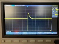
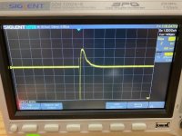
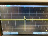
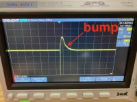
At the moment when foobar2000 starts playing (when it connects to the DAC device driver), I hear loud thump/jitter (but it's higher frequencies compared with 'normal' thump from power amp) in the speakers.
Also VU meters jump to 20% briefly.
So this happens NOT when amp starts, but later, when foobar2000 starts.

This thump comes either from a PC or from DAC, because with different DACs it's not present.
The USB cable between DAC and PC has 'USB isolator' - to eliminate things like thumps and ground loop hums.
Without it, I have a thump, AND hum, so it does something positive.
With the two other DACs that I have, the hum is even worse; this DAC is so far the best (except that it has a thump, and the other two don't).

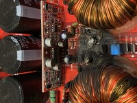
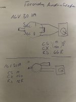
On my new, freshly built amp, when this thump happened, it blown PSU fuse (on mains). Later everything worked fine, but this morning,
during the thump, the amp onboard fuses were blown (one rail only, different rail on each channel). They are 4 amps fast fuses.
Should I increase amperage?

The best would to eliminate this thump in the first place, but I tried many times, and failed.
What else can be done to the amp/psu/dac setup, to prevent further damage?
Interestingly, my other amps don't mind that thump, only the latest one objects... (perhaps because it draws more current than others..).

PC is connected to mains via 3-pronged outlet (with ground).
DAC is powered by little psu (ground from mains is not used).
Amp's PSU is connected to mains via 2-pronged outlet (ground from mains is not used).

Any advice?

Old sansui crossover help

Hi
I got this old pair of sansui esp 305 speakers and are seing if they need some replacing/repair and what not. I was just wondering if some of you guys understand the crossover better than me?

An externally hosted image should be here but it was not working when we last tested it.


The red wire is going to the woofer, yellow to mid, and blue to tweeter

I got it to be a crossover with 1.8kHz and 5kHz points from searching the web.

Hope some insight can be given
Imgur: The magic of the Internet
Projects by fanatics, for fanatics
Get answers and advice for everyone wanting to learn the art of audio.
Join the Community
507,637
Members
7,881,827
Messages

Filter

Forum Statistics

Threads
405,933
Messages
7,881,827
Members
507,637
Latest member
noname203