Modifying a PT?

Recently received a 350W custom PT. I spec'ed it out for 115V primary, but it came with 220/230V primary instead. Cannot use this unless I run extension cord from laundry room- lol. I see from research here that primary is most likely first winding, so is there easy (or relatively easy) way to modify it- ie separate into 2 equal windings to operate in parallel for 115V operation? Or should I sell it and take the loss?
Thanks,
Jim

Possible to better -50dB THD at 1m, 108dB, 1kHz and up, with a horn/driver combo?

I would add to that, reasonably constant directivity above 1kHz, with 90-ish deg beamwidth in the horizontal plane. HD products restricted to the audible range.

I'm not well versed in horn-loaded designs, but I believe no such combination exists that's commercially available? For all I know, the limitations imposed by non-linear acoustics may prevent such an outcome...

Thanks.

Help me with this active filter modification

Hi, my active crossover, a/d/s/ 642ix, can only be adjusted filter frequencies by changing filter modules. It has instruction for modifying these modules. They also had provided table of modified values. Please find attached pictures. I’d like to have the low-pass filter frequency to be at 320 Hz. Please help me to calculate component values to achieve 320 Hz. Thanks in advance

Attachments

  • B06B1A36-2E18-4787-952D-77B1224BDEC2.jpeg
    B06B1A36-2E18-4787-952D-77B1224BDEC2.jpeg
    52.3 KB · Views: 123
  • 0AD89F07-E03C-4D6E-B766-B899C80474DD.jpeg
    0AD89F07-E03C-4D6E-B766-B899C80474DD.jpeg
    128.6 KB · Views: 127
  • 2BD4AF79-22A2-439B-B6FF-12CFFC2E1949.jpeg
    2BD4AF79-22A2-439B-B6FF-12CFFC2E1949.jpeg
    159 KB · Views: 114

Clair Bros Phase Linear 700B Series 11

I have for sale the above amplifier in mint conditon given its age.

This model was designed for Clair Bros & features a pressed steel chassis and was used by Jands Production Services.

The amplifier has been fully maintained throughout its service life.
The Phase Linear 700B Series 11 produces a conservative power output of 360 watts into 8 ohms per channel, the threshold of clipping being 450 watts per channel.

The amplifier for its vintage and design produces excellent measured and subjective performance. I know longer have a use for this amplifier.

This sale is only available to residents in Australia.
The price is $700.00. All shipping costs are paid by the buyer.

Please send a Pm if you are interested.

Ian

Attachments

  • clairbros700b2.jpg
    clairbros700b2.jpg
    8.9 KB · Views: 347

Q on Heybrook HB2 XO

Here's a schematic of the XO for the Heybrook HB2's -- the woofer for this one was destroyed by too much teenage activity so it is in the woofer replacement facility -- why is R1, C2, L3 connected to the tweeter "+" ? when I simmed it I note that it "shelves" the response. The tweeter seems to be the standard, government issue Audax 1"

An externally hosted image should be here but it was not working when we last tested it.


Here's what the actual response into a resistive load looks like:

An externally hosted image should be here but it was not working when we last tested it.

Amplifier for measurement: options

I'd like to take some acoustic measurements outdoors. Eg. empty basketball court, football or cricket pitch. Bringing a laptop to power the audio interface and microphone is great; only thing that needs AC power is the test amplifier.

So I'm looking for battery powered amp that can output approximately 1-16V into 4 ohms (~50 into 4 ohms).
Ideally self-enclosed, has audio input and speaker output connections.

Mono is fine. I get that this is a DIY Audio forum and people like to build their own, but right now I just need to collect measurements from loudspeakers.
The most I would like to do is to connect alligators clips to a SLA to a DC-input based TPA3255 based amplifier, but before I do this, is there another solution that people have used?

Cool trick from de-soldering.

A friend was over the other day to recap his crossovers. I have a solder sucker but it really doesn't clean out all the old solder and we had a hard time removing all the solder. Then I remembered this little tool I use to clean out my gas welder tips.

I could pass these tiny round files through what little holes were left after we cleared out the solder.

Works really well and easy and they are inexpensive

Attachments

  • 20200325_130953.jpg
    20200325_130953.jpg
    819.5 KB · Views: 934
  • 20200325_130959.jpg
    20200325_130959.jpg
    770.2 KB · Views: 930

Simple stereo gain stage

I'm in the process of putting together a system with a Audio Sector Gainclone kit and a Pass Labs B1 input buffer. My main sources are a phono pre and a CD player. I will also have a mini jack input for my ipod or computer output for streaming audio such as Rhapsody or Pandora. Both my ipod and computer have a pretty low output. I want to be able to match the gain on that input to the level of the CD player which has nice output and the phono pre that has a gain control. I'd like to have all the levels equal before they go through the selector switch and then into the B1.

Is there a simple gain stage circuit with a pot that I can run the ipod/computer through to give it a little boost to match the rest of the sources?

Thanks, Scott

Control line level volume

In many thread in this post I see some people asking how to control the volume/voltage of a line level signal. In many cases, people recommend using a 10k potentiometer (optimally it should logarithmic but let's not take this into account right now) as a voltage divider connecting the left pin of the pot to GND, the middle pin will be the line level with its volume decreased and the right pin would be the line level.

Some people says it works just fine, but I am wondering here: the line leve spec recommends using a 100 to 600 ohm resistance in the line out level. Using the 10k pot as above, would result in a much much higher resistance.

Also, many line inputs have already 10k ohm (or even 100k) resistance so using a 10k ohm at the line output shouldnt be a good idea (I dont know why, but I think it shouldnt be correct).

So I ask you guys: why most people recommend using a 10k ohm potentiometer at the line level out? Wouldnt it be much better to use a 1k ohm potentiometer since you would be much closer to the spec (600ohm) and much further away from the 10k-100k resistance of most line input?

Replacing 7355 power tubes with 7591s (H-K TA500x Receiver)

I've read a lot of DIYaudio posts but haven't posted much myself:well here goes. I got into vintage tube radios about three years ago and that lead me to a Harman-Kardon tube AM-FM receiver. This dude weighs like 40 pounds and has twenty tubes; it will heat a small house but I love look and sound of this vintage of gear. I have gone through this receiver and brought it up to specs but I m having trouble finding power tubes (7355s). I have been able to find un-matched 7355s but it really needs a matched quad to perform as designed, and they are not available. I did some research on a replacement and the closest pentode to a 7355 currently in production is the 7591. 7355s and 7591s operate in push-pull at pretty similar voltages except the Grid #1 voltage, which are -23.5 vs -16, respectively. So how do you change the grid #1 voltage? H-K brings the cathode ground up with a voltage divider circuit that also drives the filaments of three pre-amp tubes instead of having true negative dc. And to boot, on my unit, the aforementioned filament voltages are low (8.9, 8.5, 7.6). Instead of trying to make a new divider circuit, I decided adding a new power supply would be the answer. The new power supply has an adjustable negative dc for grid #1 and powers the pre-amp tubes at 12.6 volts (±10%). The bonus to having an adjustable -dc is I can properly bias either 7355s or 7591s. I have completed step one, which is to install the new power supply, re-power the pre-amp filaments, connect grid #1 circuit to the neg dc supply, and connect the cathodes to ground. I haven't modified the tube sockets yet so I brought it up today with 7355s and it biased very easily and performed very well. I wasn't sure what effects the increased filament voltage in the pre-amp and increased plate to cathode voltage in the power tubes would have, but i'm happy to report no new hums and a slight increase output, particularly in the phono pre-amp. I attached the schematic of the mods. The only modification left is to decouple pin 4 on the power tube sockets, and put a jumper from pins 8 to 4. After the sockets are modified, I'll try try to bias a new matched quad of re-production Tung-Sol 7591s power tubes and report back. Thanks for reading.

Bill

Attachments

ROAR 12 -Disappointing Results

Hi Folks,

I think this might be my first post here, so please go easy. I recently completed a Martinnson ROAR12 build using a Beyma 112nd/w. It simulated quite nicely in Hornresp


ROAR 12 SIM.PNG


The build was easy enough, but the results were somewhat interesting. The intended use is a small PA for my farm and as the bottom end of a bass guitar rig.


I am fortunate enough to be able to measure in a paddock 100+m from anything reflective. The results are as follows (uncorrected SPL) -

Roar 12.jpg


The efficiency is simply ridiculous at 100hz, but the low end is rather disappointing. 45hz is some 15db down on 100hz. It still outputs a surprising amount of noise at 45hz, and a simply ridiculous amount of noise at 100-150hz. The 1w/1w efficiency at 100hz works out around 110db and if I eq this out, the woofer seems to run out of excursion down low.

I have read some threads where the merits of the ROAR design were questioned, but not resolved.

Has anyone built one of these and has similar results? Is there a likelihood I have stuffed up something in the construction, or is it more likely that those questioning the design and simulations were correct?


Any input would be appreciated.

Lax

MTM style dual-driver FR with whizzers works OK or not?

Well MTM minus the T 😉
for you speaker building guru's I'm curious to know, does it work OK to use two full range drivers per cabinet to raise the sensitivity?
You have to do sim's, and modify the cabinet or can use the same cabinet design for the given driver?
Spacing between the drivers is critical?... I assume adds another complexity to figure out or experimented with?
What about if the drivers have a whizzer cone, does it matter, and can it still work?

Dave, has anyone tried this with the Frugel horn or other cabs?
a quick search found this about dual drivers - I will edit this post as I find more ...
http://www.planet10-hifi.com/downloads/Dual-Driver-Wiring.pdf

below I added a speaker designed by Omega sold by Decware - so I guess it works.

Attachments

  • 2022-11-15_10-59.png
    2022-11-15_10-59.png
    101.4 KB · Views: 92

How long to expect 12HL7 to last in SET headphone amp?

I built myself a 'spud' headphone amp a few years ago that's nothing more than a 500VCT power transformer with full wave solid-state diode rectification, CLCRC DC plate supply, 6.3VCT (AC) heater supply, two 12HL7 pentodes wired triode, a pair of Edcor 8k:50 SE OPTs, and the usual complement of jacks and a volume control.

The 12HL7s are being run pretty hot, at about 150V plate-cathode and 45mA Ip, so Pdiss is almost 7W. That's an attempt to keep the rp down low to compensate for the not-very-generous primary inductance of the very cheap OPTs. The max combined plate+screen dissipation for 12HL7 is 11W, so I figure 7W is low enough that the tubes should have a decently long service life.

Being that it's a headphone amp for bedtime listening, I sometimes fall asleep and leave it on overnight. Sometimes I forget to power it off when I get up, so it stays on all day.

I find that the 12HL7s go noisy after about a year and a half of use. One or the other of them will start to crackle, which is horribly uncomfortable in headphones! (Ouch.) My question is, should I expect these touchy high gm RF pentodes to go noisy after a year or two of use, or does it sound like something is wrong and I should start looking for a problem?

I have 1k ohm grid stoppers on the 12HL7s and 0.1uF 100V film caps bypassing the heater supply to chassis. Perhaps there are more oscillation suppression steps I should take? 10 ohm plate stoppers?

Build Thread - A New Take on the Classic Pass Labs D1 with an ESS Dac

There is a critical design update here:

http://www.diyaudio.com/forums/digi...sic-pass-labs-d1-ess-dac-173.html#post3662046

Please read this before ordering any parts!!!! I will update the BOM attached below at some point and see if I can have up replaced.


Hi Guys,

This will be the official build thread for the I/V stage PCB group buy. Please post all build related questions here.

Also, feel free to post pictures of your build, chassis ideas, parts suggestions etc...

I'll start things off with a final schematic and SMD BOM which people will need for the build. I'll have a BOM posted for the remainder of the PTH parts, and it will include all the parts I used in my build.

Cheers,
Owen

Attachments

Help with MLTL for Alpair 10.2?

I been lurking on this forum for a while, learning from the kind and knowledgable folks here. Thank you! Years ago, I built MLTL bass boxes based on a design of Paul Kittinger, using Martin King's programs. Loved it!

Now, I'm inspired by the Pensils and Sebelius to design and build an MLTL tower using Alpair 10.2's. To fit in my space, I'd like the cabinets to be a bit smaller than the Pensil. The first diagram gives the general dimensions. I did a bunch of modeling using Hornresp. The pictures show the model parameters I came up with. The modeled response looks pretty good to me, with a bump ~42hz. Mouth velocity is a little high near the driver x-max. Otherwise, I would have make a narrower shallower port. Did I model this correctly?

I built a test box and measured it. The test box is slightly larger than the model to allow for some adjustments. But, it's pretty close. The driver has ~150 hours of break-in time. The near field measurement look pretty good. And it sounds pretty good! The bass is extraordinary for such a small driver.

My first question is about the FR chart dips in the 100hz-200hz range. Some were measured at 3', others were measured at the listening position of 10'. Is this floor bounce (carpeted room)? Rear wall bounce? A gated measurement problem? Poor cab construction? Interference due to distance between the driver and port? Should I do anything about this?

My second question is about baffle step compensation. I find that the speaker sounds more natural with a ~2db baffle step shelf starting at ~1khz. Have any of you found the same? Do you think building a full-size Pensil would increase the low end and midrange enought to avoid the need for baffle step compensation?

Any advice would be appreciated!

Attachments

  • Screenshot 2022-09-01 213055.jpg
    Screenshot 2022-09-01 213055.jpg
    66.8 KB · Views: 174
  • Picture1.png
    Picture1.png
    15.4 KB · Views: 159
  • Picture2.png
    Picture2.png
    9.4 KB · Views: 149
  • Picture3.png
    Picture3.png
    17.1 KB · Views: 161
  • 20220724_200355.jpg
    20220724_200355.jpg
    408.6 KB · Views: 160
  • 20220726_083808.jpg
    20220726_083808.jpg
    351.6 KB · Views: 153
  • 20220726_223458.jpg
    20220726_223458.jpg
    385.7 KB · Views: 172
  • 20220731_162751.jpg
    20220731_162751.jpg
    471.7 KB · Views: 174
  • 20220828_112659.jpg
    20220828_112659.jpg
    474.8 KB · Views: 297
  • Picture4.png
    Picture4.png
    11.1 KB · Views: 150
  • Picture5.png
    Picture5.png
    12.4 KB · Views: 128
  • Picture6.png
    Picture6.png
    12.9 KB · Views: 138
  • Picture7.png
    Picture7.png
    17.7 KB · Views: 136
  • Picture8.png
    Picture8.png
    14.1 KB · Views: 143
  • Picture9.png
    Picture9.png
    22.9 KB · Views: 182

Parallel operation of triodes.

What's the difference in noise performance of two triodes in parallel ( Anode, grid and cathode connected directly in parallel ) and one with a common anode load and separate cathode resistors with bypass capacitors ?
Unless the sections are very closely matched , the direct connection will not ensure identical operation of the two sections. Which is a better way to operate in 'parallel' ?

Conrad Johnson had a design with 12 tubes in parallel. How did they do it ?
IIRC some designers claim that parallel operation of tubes ( or even SS chips) sound worse than single device operation.

Is this observation confirmed now ?
Cheers,
Ashok.

Attachments

  • parallel operation.jpg
    parallel operation.jpg
    19.9 KB · Views: 2,710

Jurassic Bose: the Bose 2201...

First, let me automate the inevitable debate that will follow. This is in C code, which is almost as old as the Bose Co. itself 🙂

FlameWar(void)
{
while (TRUE)
{
printf("Bose sucks!\n");
printf("No! Bose rules!\n");
}
}

Ahem! Moving right along, Soldermizer has been main-tracked, actually working on relevant DIY stuff the past few months. He just built a shelf unit for his garage. Something actually practical for God's sake! This is very out of character for him. However, his motive is pure: he now can more easily store his paint cans for his continued "faux [pas] finish" interiors, wood graining his '09 Suzuki (yes really, looks pretty good...) and water marbling with oil paint (fun and very messy.) Now what, you ask, does this have to do with Bose? Damned little to be honest, but here goes. The point is that Soldermizer hasn't devoted the usual amount of time he usually does to idiotic stereo ideas. Thus today's installment.

Everybody who knows Bose usually "knows" the first product was the 901. Not so. Two years prior was the very odd 2201. This was if I remember correctly, a pair of 1/8 sphere speakers. Each was a polyhedron of 22 active (and individually EQ-ed?) drivers. Bose was attempting to re-create a sphere diffusion or some such idea. I think he later abandoned this idea, but ... did he, or anyone else, do further research on it? Could it be that the dear Doctor, before he devolved into that phenomenally successful marketer and arch nemesis of audio snobs everywhere :darkside: , was actually onto a valid concept he abandoned too soon, you know, sort of like Tesla* giving up on his time machine (kidding!)? :clown:

Is it possible that he did not have enough technology in 1966 to adequately build his speaker? In 2015 China sells us more than fireworks 🙂 Four dozen (small) amplifiers and the same amount of DSP filters are within the budget of many experimenters. :wiz:

This would be a fascinating area to research, even if just in the literature. Anybody ever heard if this sphere idea was developed further?

*We should all be thankful to Tesla and his discoveries. If it weren't for him, we would not have AC current and our speakers would really sound like crap with only DC current 🙄

For Sale TAD TD-2001 High Frequency Compression Drivers

-- SOLD --

1pair TAD TD-2001 H.F. Compression Drivers
New in original packaging, opened for test fitting and photos.
$2,000 for the pair
Shipping negotiable world-wide

will throw in B.Edgar 650Hz Tractrix wood horns if wanted, but one mounting plate is missing 🙁

Attachments

  • PXL_20221108_203311032.jpg
    PXL_20221108_203311032.jpg
    481.8 KB · Views: 159
  • PXL_20221108_203316114.jpg
    PXL_20221108_203316114.jpg
    409.2 KB · Views: 132
  • PXL_20221114_222141036.jpg
    PXL_20221114_222141036.jpg
    498.5 KB · Views: 139
  • PXL_20221114_222156437.jpg
    PXL_20221114_222156437.jpg
    434.7 KB · Views: 143
  • PXL_20221114_222216622.jpg
    PXL_20221114_222216622.jpg
    502.5 KB · Views: 156
  • PXL_20221108_203216000.jpg
    PXL_20221108_203216000.jpg
    472.1 KB · Views: 162
  • PXL_20221108_203232181.jpg
    PXL_20221108_203232181.jpg
    438.9 KB · Views: 196
  • PXL_20221108_203240761.jpg
    PXL_20221108_203240761.jpg
    313.6 KB · Views: 152
  • PXL_20221108_203354234.jpg
    PXL_20221108_203354234.jpg
    413.1 KB · Views: 179

Very small solder removal problem

I'm trying to repair a ribbon cable in my MacBookPro. It carries the power for the display back light and the ribbon has cracked, a known issue. The local Mac store want $600 to fix it, and new display with cable is $250. The cable is not replaceable. That's why I'm attempting the repair.

So far I've made decent progress scraping the insulation off the cable, tinning the tracks and almost getting it repaired with thin wire strands over the tracks. But as you can see from the photo below, I've got too much solder on a couple of tracks and it's bridging where there shouldn't be a bridge. I'm having a very hard time removing the excess solder. The work area is small, about 4mm across.

Chemtronics solder wick size #3 is somewhat too wide and thick, it's not sucking up the solder. I don't have a solder sucker.
Melting the solder and flicking it off with an Xacto knife isn't working, the solder stays put.
Solder is Kester SN63PB37 0.02" diameter.

Anyone have an idea for getting these solder blobs off the traces so that I can start over?

solder trouble 1.jpg

"AKG" tube mic PSU help

This is one hell of a long shot, but i'm getting somewhat desperate, so here goes.

I recently got myself an ancient knockoff of an AKG P820 tube mic from a local store brand, per the service manuals, at least the PSU is a direct 1:1 copy. Now, the PSU appears to be dead, the T125 fuses blow instantly and the light never comes on, this model is basically wholly undocumented but there is one forum post from 2012 that indicated a possible faulty transformer. Upon desoldering the transformer to take some DCR and impedance measurements off the crusty board, i promptly lifted all pads. That, combined with the no-name unspec'd transformer and the generally subpar parts, have given me the idea to just design a brand new PSU basically replacing everything except for the pattern selection section. So my question is, is there anyone that'd be able to help me figure out what kind of voltages i'm looking at so i can get started? I will post pictures and link to the service manual in a couple of hours when i get home from work.

(I have contacted both the store that used to carry them as well as AKG and it would seem i'm SoL as far as getting original parts, despite the AKG variant being a currently available product, i'd frankly prefer an improved self design version anyhow)

Thanks for any help!

For Sale BMS 12N630-8ohm 12" Neodymium Ultra Low Distortion Woofers

BMS 12N630 12" Neodymium Ultra Low Distortion Woofers
8ohms, 600W

2 pairs available
$500 a pair + shipping

Attachments

  • bms_12n630_t_data_2014-07.pdf
    bms_12n630_t_data_2014-07.pdf
    578.8 KB · Views: 60
  • PXL_20221115_175735245.jpg
    PXL_20221115_175735245.jpg
    428.3 KB · Views: 142
  • PXL_20221115_175800157.jpg
    PXL_20221115_175800157.jpg
    411.8 KB · Views: 161
  • PXL_20221115_175907131.jpg
    PXL_20221115_175907131.jpg
    528.7 KB · Views: 261
  • PXL_20221115_175912815.jpg
    PXL_20221115_175912815.jpg
    487.2 KB · Views: 227
  • PXL_20221115_175917803.jpg
    PXL_20221115_175917803.jpg
    474.8 KB · Views: 186
  • PXL_20221115_180005751.jpg
    PXL_20221115_180005751.jpg
    419.4 KB · Views: 162
  • PXL_20221115_181945781.jpg
    PXL_20221115_181945781.jpg
    444.3 KB · Views: 170
  • PXL_20221115_182057166.jpg
    PXL_20221115_182057166.jpg
    464.3 KB · Views: 149

JLH 1450 Phono Boards. Are they available?

I fell over Robert Jenkins WEB site offering PCBs of this JLH design from the schematic on Paul Kemble's site.

It's something I'd have built from the Hart kit at the time if I'd had the money, so I thought why not, scratch an itch, and sent him an email. No response. Tried again some time later, still no response.

Anyone purchased any or had any contact with him?

Bourns PRM16 motorized pot — very simple Q

Hi friends

This is an embarassing question: What is the orientation of the backside's drawing (with the motor's connection pins) in the datasheet (see below)? The pot's connection-pins downwards I guess? (So, looking at the pot's back with the pins downards oriented, V+ is on the right side?)

:spin:
I kinda think it's either way and can be just tested (swap the wires if it doesn't work), but I'd like to have it confirmed because I have a little issue here (motor's not turning although everything else seems to work), and it would be comfortable to have one variable less...

Thank you

Attachments

How to change the output voltage from 13.8V to 12v with this circuit

Hello

I have a Pyramid power supply which gives 13.8V . I adjusted the pot inside the PS but can get near 13.2volts at lower point. I want 12 volts to feed a Mac mini. This circuit seems interesting because it uses discrete parts instead of ubiquitous 78xx with a pass transistor. Any other mods suggestion ? Thanks

Attachments

  • 13.8V supply.jpg
    13.8V supply.jpg
    209.8 KB · Views: 329

For Sale 50pcs Caddock MP930-0.25R-1% thick film resistors

I have 2 Tubes with 50 pieces Caddock MP930-0.25R-1% thick film resistors without use .

I’m asking for 1 tube / 50pieces €75

Power Rating: 30W with Heatsink / without 2,25W
  • Product Range: CADDOCK - MP930 Series
  • Resistance: 0.25ohm
  • Resistance Tolerance: ± 1%
  • Resistor Case Style: TO-220
  • Resistor Element Material: Metal Film
  • SVHC: 27-Oct-2004 & 26-April-2004
Price + PayPal 4% + register shipping expenses. Shipping form Finland

Rgds
Finwbu

IMG_20220209_094009.jpg
IMG_20220209_094002.jpg
IMG_20220209_093958.jpg

Rockford Fosgate 250a2

Hopefully this one is a little more simple. Rockford Fosgate 250a2 PC-2035-G. Typical blown channel, but when I went to replace an open source resistor I noticed they are 0.03 ohm, not 0.1 ohm as I'm used to seeing. Also, R261 & R235 are 0 ohm jumper "resistors", and R262 & R234 are excluded. The amp hasn't been worked on before, and matches another 250a2 I looked at.

The main issue is I don't see much available for 0.03/30mOhm 3W 5% resistors. If I changed to a 0.1ohm source resistor, would I restore R261 and R262 like the earlier revisions? I only have schematics for Rev B & Rev C, which show 0.1 ohm source resistors and R261 as 20 ohm, R262 as 10 ohm. The IRF540 side of the 200 channel is the only damage (inc/R252, Q216, D204). Would I do the IRF9540 side as well?

IMG_20221114_234436026_HDR_copy_1600x1200.jpg

Attachments

  • 99_amps_punch_g250a2_schematic.jpg
    99_amps_punch_g250a2_schematic.jpg
    130.1 KB · Views: 96
  • 315082518_830507424662454_5969920006918038152_n.jpg
    315082518_830507424662454_5969920006918038152_n.jpg
    461.6 KB · Views: 71

Reconditioning a Audio Research LS-15 Tube Preamp Advice Needed.

Hi , I recently bought a Audio Research LS15 tube preamp that is working and sounds very good. It has an issue though. It after it has been on for a while say maybe an hour It automatically shuts off. turning it back on it will work for a little while then shut off again. I bought it knowing this and without knowing how the unit was designed initially thought maybe it was a just a cold solder joint or a crack in a trace maybe a wonky tube socket.
Upon receiving it i discovered that front panel controls are not analog pots and switches but digital and are handled by a 8-bit microcontroller and a couple 8-bit shift registers. In the manual it warns that static discharge could potentially lock up the MCU and require a restart. That got me thinking this is a older unit circa 1998-9ish and maybe the electrolytic caps are out of spec and when it heats up for a while maybe voltage fluctuations are causing the MCU to switch the unit off?

I figure maybe the best course of action is to replace all the electrolytic's and then go from there?
My question is there are no electrolytic's in the audio path just in the PSU and MCU sections , They are all Nichicon VX(M) series caps except the two 470uf (M) 200V main caps which are SMH series snap-in types, all are out of production. Can anyone tell me what series caps would be suitable as modern replacements? They are all temp rated 85c, would it hurt to be looking at 105c? One of them on the underside of the circuit board is a 47uf 250v polar Axial which i don't think is made anymore. Could i just lay a radial type on its side and end the leg over the top? Thanks in advance for any help.

315320997_508763147831169_8884225602826788639_n.jpg

Attachments

211 SE tube amp has developed ticking sound in both channels, after amp on 3-5 hours

I have an excellent probably 20-22 year old, 211 SE amplifier rated at 18W per channel. I use it to drive my mids/tweeter D'Appolitto speaker. The amps designer is no longer with us. In September of this year the amp developed a ticking sound in both channels, not loud but when you get close to the drivers you'll hear it. If I put my lowther PM2a in then it is loud (ticking) as expected from a 97db speaker. The odd thing, to me, is that the bass driver which is driven by a 200W solid state amp also ticks, and this stops as soon as I turn the tube amp off. I am pretty confident the source is the tube amp and probably some old, heat affected components like plate resistors, resistors in the 211 filament circuit, possibly old electrolytic caps, after all the amp is 20 years old and throws some serious heat.

I have attached a schematic which the designer sent me a few years ago, I highlighted in yellow a capacitor in the filament circuit of the 211 which calls for a 3.5uF, 100V capacitor. In reality installed is a 1.25uf, the K I believe is 10%, 100V MPC style. I am not a technician but does that look ok to you 1.25 installed vs. 3.5 schematic. Also at the amps input I have a texas component 1K bulk metal foil resistor which connects to the grid of the 6sn7, also, according to the schematic a 200K ohm resistor runs from the grid side of the input resistor to ground. Installed in the amp is a 79K ohm resistor, not the 200K. Is that an issue?

I replaced the plate resistors (15K and 12.5K) earlier this year with mills MRA 12 resistors (15K and 12K) and earlier this week rechecked my soldering to make sure I had good joints, so hopefully these are not the cause. Visually looking over the components the 1K resistor in the 211 filament circuit looks a little heat beat up and the board below a bit brownish, I have 10W, 1K vishays on order to replace these. As stated in the title the ticking does not start until the amp has been on anywhere from 2-5 hours. You can see this 1K resistor right in front of the yellow capacitor in the attached photo.

Basically I am looking for advice on what you think could be the most likely cause of my ticking and if the 2 cases I note above are fine (they probably are) as is or should I revert back to what the schematic says. The components mount on vector boards with swaged terminal posts and these can be wired from the top or bottom. Things can get pretty tight in there, so soldering to these is not the most fun thing to do. Should I just replace some older components just because they are old and if so what priority should be given?

Thank you!!


211 schematic.jpg 1.25uf cap in amp.jpg

Transformer fuse rating <25VA

Hi all.
I have been reading conflicting arguments when it comes to fuse sizing for transformers. Especially when it comes to smaller transformers say <25VA.
To complicate things further some manufactures include a thermal fuse in the windings.
Reading some of Rod Elliotts articles suggests that smaller transformers can’t be made safer with the use of external fuses. I still can’t understand why he says so. Maybe someone can explain?
I have opened up many wall wart type packs only to find no fuses and sometimes only thermal fuses. What if i find a replacement transformer that has no thermal fuse?
I do mainly repairs and want to give my clients the assurance when having to replace a transformer in their gear.
Thank you in advance all!!

DIY USB in XMOS 6 to 8 channels output device to make his own multichannels DAc

Hi,

I know DIYhink sold one, but are you aware of such things in Europe ? Basicly a three I2S output for a 3 ways active loudspeakers

Well I can buy too a Behringer UMC1820, but I have already three stereo dacs that just need to see each an I2S.

something like that : https://www.diyinhk.com/shop/audio-...et-type_c_new_and_slim/159-esd_protection-2kv

thanks

Hypex NC400 Connection kit turn-on pop

I just build a stereo amp using two NC400 modules, a SMPS1200A400 and the connection kit

4_smps1200a400-onto-2x-nc400-connection-kit.jpg


Im using the Amp Enable pins in the board to connect both NC400 nAMPON wires, but for some reason, Im getting a slight turn-on pop on the speakers. I've read some other builds not using this PCB and they state that the amps have no pop whatsoever and Im wondering if this pop is the result of using this board.

Here is a pic of my current build
I0ZvyCO.jpg

Presonus Eris E8 "upgrade mod" (and a strange story..)

Hello,

i wanna share with you quite a strange story
i bought the Presonus Eris E8 quite a while ago (like in 2016) and was blown away by the piercing high frequencys (and the otherwise really good sound), well the -2 to -4db highshelf eq helps that get spoken about quite alot on the web for the Eris but it kept me curious how sound engineers can bear the sound while working since they are studio monitors and they should be used "flat" for that purpose
i even send them back to thomann who measured them, all ok but i kept going and send them back to Presonus directly and got a new pair since i thought they are defective in some way (well ... my first "good" speakers and no clue about audio at that time)

well, since then i lived with the EQ setting on the back of the speakers for -2 to -4db high frequency reduction and since i use CamillaDSP in moode i Eq`d it there

fast forward, since a few months i noticed that
A. my left speaker/tweeter isnt happy with some frequencys, in layman terms it sounds like it "breaks up" or clips or something even if i just listen at about 75-80db still unsure what it is but for most music it sounds fine, sinus sweeps sound perfectly fine too! (please let me know if you have a clue)
B. the right speaker isnt happy with some low frequencys, i think its the resonance frequency of the speaker itself, something rattles inside if the right frequency gets hit

now i found recently a good song that hits the right frequency with each bass and thought "lets look inside" maybe something loosed up or something, everything was fine so i thought maybe its the cables to the speakers that rattle against something, so i took some cable ties and remanaged the cablemanagement inside and where the tweeter and woofer cable where tied together in the first place, i actually seperated them, i listened and HUH the high frequencys sound much better now.... so i also did this mod for the left speaker and yea, improvement overall in the high frequencys, i was even able to turn the EQ off, well i ended up just reducing the high frequency reduction to around -1.5db where it was before -2.5

Now im questioning myself a bit, is it even possible that the high frequencys sound worse if the cable of the woofer touches the tweeter cables? is it some kind of "overspoken" signal? and if yes why the hell the manufactor decides to tie them together?

Curious what you guys think! and maybe you can help me with the tweeter problem in the left speaker that sometimes i think also apear in the right speaker but by far not as worse, is it maybe just what we call in german "Klirrfaktor" ?

F6 build

I’m interested in building an F6. I’ve only recently begun looking at some of the information available here and it seems like a fairly straight forward process. I would be using parts from the diyaudio store. Do these parts replicate the Pass design accurately enough? I just want to be able to duplicate the amp exactly as Pass intended. I’ve successfully built a pair tube amps and a preamp from kits as well as a pair of speakers; a Dick Olsher inspired Basszilla Platinum. While I feel confident in my soldering skills and identifying components this looks a bit more demanding. This amp will replace a 20 year old SS Marantz ht receiver.
This is a a great forum. I look forward to your help

Shielding EI Transformer

Finished a phono preamp build. Used a cheap EI transformer to generate the AC voltage needed for the +12V/-12V. When I powered the preamp up I got hum. After some troubleshooting I decided to power the preamp with two 9V batteries, bingo no hum!

Next thing I do is energize the transformer but leave the secondaries disconnected. Testing for hum that is being coupled to the audio signal. Doing this I got hum again.

I added an IEC filter as I suspected there was some DC on the incoming AC power line. This helped a great deal with the hum but some still persists.

What can I do to minimize the hum now? I have lots of copper shielding tape left over from shielding a guitar. I don't really want to go buy a toroidal transformer.

Here is a pic for reference (click to enlarge)


FURY amplifier

I decided to highlight this scheme as a separate topic, because a concept has been formed both in terms of topology, element base, correction features, and, in fact, sound.
This scheme was called Fury (FURY).
circuit features:
1) the circuit of the voltage amplifier on JFET transistors in cascode inclusion
2) two NFB circuits, one of which covers the output capacitor, the second also corrects the stability (taken from the output of the amplifier)
3) complementary hexfet output
4) deep NFB (not less than 70dB)
5) inverting inclusion

The block diagram of Fury consists of three stages:
1st cascade on the field (jfet) with inverting inclusion
2-nd cascade of field devices (jfet) with dynamic load and low-impedance output for coordination with output stage
3rd cascade single follower with high-resistance input and with dynamic load + push-pull output stage on hexfettes in class AB
The nuances of the scheme:
* the first two stages without load have a gain of 95dB
* The contour of NFB at the input determines the overall gain of the circuit at 19.2 dB
* maximum input voltage (amplitude 3 volts)
* added RC input f = 816kHz to reduce dynamic distortion
* the second NFB circuit goes to the gate of the second stage, it is connected relative to the reference voltage of 13 volts (implemented on the zener diode), this circuit carries out correction of the amplifier at high frequencies for its stability and sets the operation mode of the output stage by constant voltage.

P.S. In the event of a break in any of the negative feedback loops or two at the same time, the circuit remains operational.
Nuances of the scheme of the 3rd cascade:
* at the input a field + bipolar transistor, which takes a signal from the source of a stable current source, because lower pre-amplifier output impedance is needed to match these stages
* dynamic load performed on mosfet IRF510
* The bias circuit of the output stage is made on the BD139 transistor with the IRF530 transistor - it provides smooth adjustment of the initial current of the output stage 100mA
* The thermosensitive element is the BD139 transistor, it is he who is screwed to the radiator.
* The use of IRF630 / 9630 turned out to be quite a musical complementary pair ...

Circuit Parameters:
* Ku = 19.2dB
* Uin max ~ 3V (amplitude), Uin nom ~ 2V (amplitude)
* P out (RMS) max = 40 watts (4 Ohms)
* slew rate SR = 5.84V / microS
* Frequency response in the frequency range 1-100000Hz is 0.05dB
* uneven phase response -1.5 degrees (20 kHz) and -7 degrees (100 kHz)
* delay at a frequency of 100 Hz - 0.24 microS, at a frequency of 20 Hz - 1.4 microS, at a frequency of 5 Hz - 96 microS
* output impedance R (i) 0.34 ohm ...
* the depth of the negative feedback in the frequency range 1-1000Hz is 76dB, at a frequency of 20kHz - 70dB
* THD distortion (nominal) at a frequency of 1 kHz less than 0.001% (0.0004%), at a frequency of 20 kHz - 0.006%
* initial current of the output stage 100mA
* power scheme - you can use unstabilized

Attachments

  • Fury 2020 .jpg
    Fury 2020 .jpg
    99.9 KB · Views: 1,432

An electronic turn/thread counter

I created this contraption 40~45 years ago, but since it is just ordinary, run-of-the-mill circuitry combined with a lousy implementation, I never cared to publish it before.
However, even though the implementation is unremarkable and completely outdated, the principles are sound and could be reused in a more modern reinterpretation.

1668456645741.png


The principle is simple: a mechanical probe (a strip of spring-metal) is swept across the ridged surface to be analyzed. The probe is in contact with a piezoelectic sensor, which generates a sharp pulse each time the probe jumps from one peak to the next one.
The pulses are shaped, filtered and counted after being subjected to hysteresis to remove false/double counts.
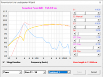
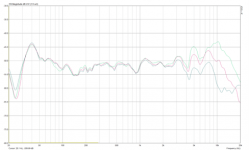
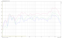
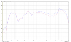
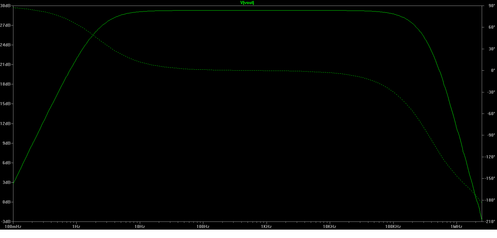
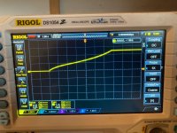
This oscillogram shows the signal at the input of the schmitt trigger when the probe is swept quickly through a M4 threaded rod:

1668456804466.png


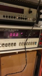
The pulses are accumulated in a two-digit counter, which limits the maximum count to 99, but in practice it is usable to ~200: it is easy to see if a winding or a thread has more than 100 turns, and in this case if you read 35 for example, it means that the actual number is 135.

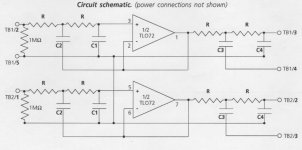
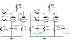
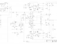
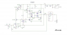
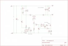
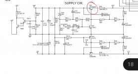
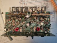
The circuit is slightly more complex, to take into account the realities of such measurements:

1668457010732.png


When you prepare yourself to make the test, you generally have both of your hands busy, but you need to push the clear button and then place the probe in contact with the object you test, without accidentally touching something else, or landing too roughly on the surface; in the meantime, you have your gaze focussed on the work area, not on the counter, and you may miss an accidental count or two.
To prevent the situation, Lachesis is fitted with a rudimentary sequencer: when the "Start" surface is touched or brushed, a timer is initiated, providing a 6-second dead-time before any count can be registered.
When the 6 seconds delay is elapsed, counting is allowed and the status is signalled by a red LED and an (optional) acoustic signal.
The active phase lasts 90 seconds, and its end is signalled by the green LED and the muting of the audible signal. The probe can then be safely removed without risking to alter the total.
The tester can also operate in a completely manual manner.
The schematic is not fully detailed, as it would make little sense: even if someone wants to duplicate exactly my build (this would make little sense), it would be very easy based on the datasheets of the IC's used.
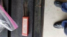
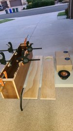
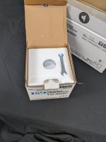
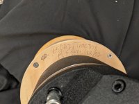
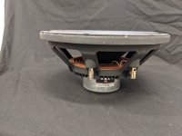
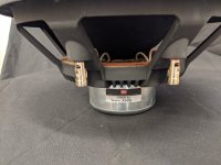
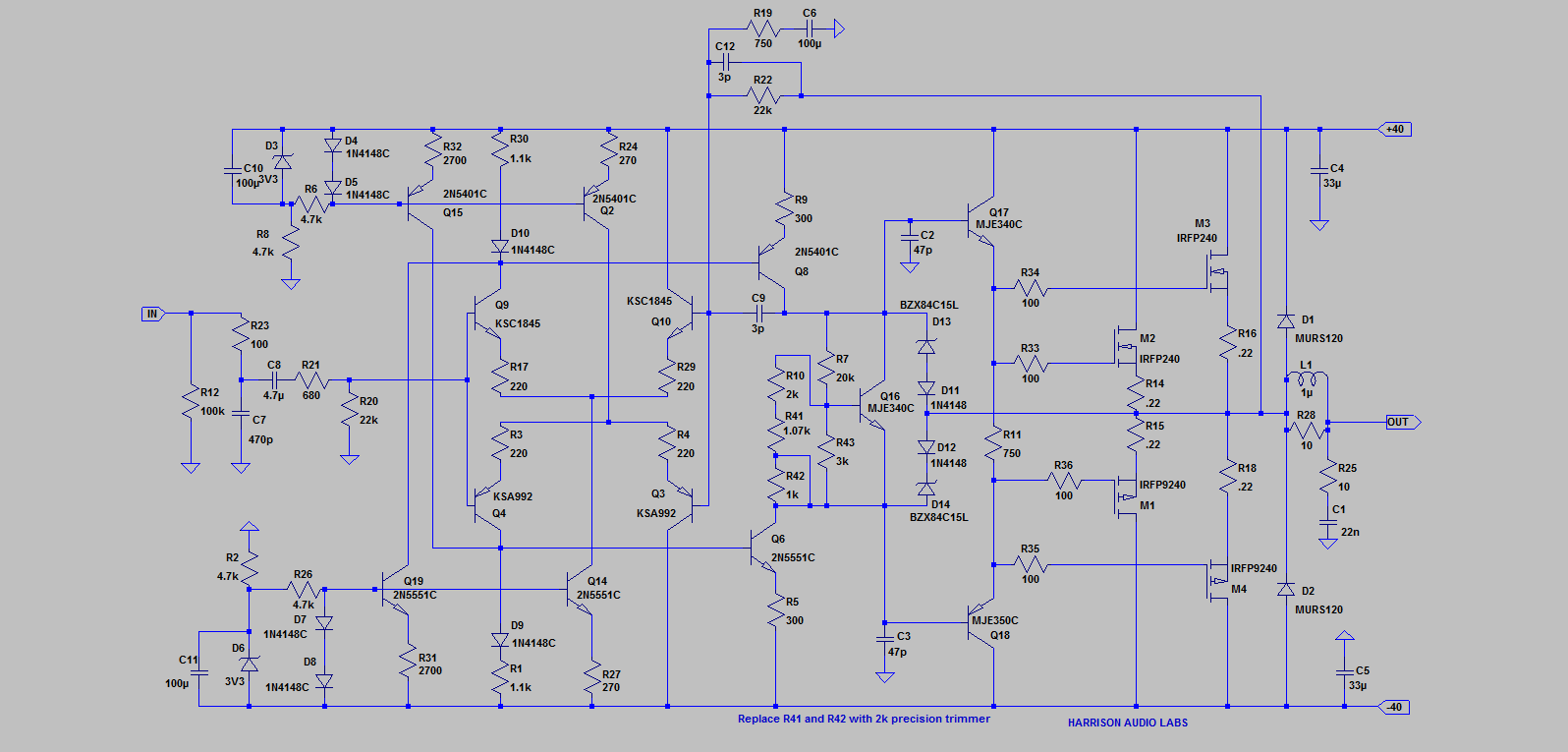
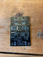
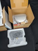
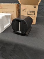
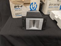
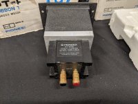
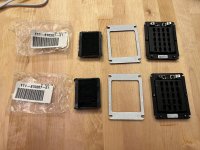
This is the probe:

1668457596731.png


1668457702457.png


1668457913411.png


It is pluggable, but in fact I never built another one.
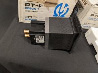
The piezo element was salvaged from an old PU cartridge, and inserted into a silicone sleeve. The sensing element and the spring strip were then inserted in a common silicone sleeve and pushed inside a brass tube:

1668458345265.png


The silicone provides the elasticity, the mechanical linking and the damping. IIRC, the metal strip came from a razor-blade, and has a thickness <0.1mm, setting the maximum possible resolution.
With this particular piezo element, the open-circuit voltage exceeds 10V and does not require amplification.
Other models could have widely different outputs.
An electrodynamic sensor could probably be used too, with the right signal-conditionning.

A modern version would be based on a µcontroller, and have loads of additional bells and whistles, but even this rudimentary version is useful, especially for people like myself: when something goes wrong during the winding process, I tend to concentrate on the problem and lose the count as a result.
When this happens, a quick sweep provides a definitive answer (sweep 3 or 4 times, for confirmation, like for a bank-note counter)

Comparison Bohlender & Graebener Neo3W and Neo3PDR in dipole mode

Today I did some measurements on the B&G Neo3W and Neo3PDR. Biggest differences:

- Neo3W has approximately 3 dB higher sensitivity
- Neo3PDR has better dispersion in the top octave
- Neo3W has a smoother transition from dipole to beaming

EDIT: too bad, the pdf is too big to upload. Try this link: [removed link]
I hope it works.

EDIT2: apparently not too well. I'll have to try something else.

EDIT3: I've got a zip uploaded, but without the pictures.

EDIT4:

An externally hosted image should be here but it was not working when we last tested it.

An externally hosted image should be here but it was not working when we last tested it.


http://img843.imageshack.us/img843/6442/measurementsetup.jpg
http://img651.imageshack.us/img651/5986/photoofbothtweeters.jpg

Attachments

SRPP vs CCDA for DAC output stage?

Hello, I have an urge to play around the miniature 6N16B and I want to use it as DAC output stage. Ive came accross two schematics that I like.
One is classic SRPP, the second is CCDA or constant current draw amplifier. You have two almost the same stages dc coupled together and one of these stages is anode gain stage, the other cathode follower. The idea behind this is that when signal is at the input, one tube will conduct equally more as the other one will conduct less - so the current draw from the power supply will be (more) constant. I have a question will this work in the reality like this and will it be better than using one SRPP stage?
My powersupply will be solid state, with choke input, and with electrolytic capacitors (maybe I will split it with some resistors or more chokes to high quality final filtration oil capacitor).
Do you really think 6N6P, E88CC, E80CC... are better than 6N16B? I have these tubes at hand.
Cheers, Michal

For Sale Dynaudio Esotar T330D + Esotec 15w75 15W-7504 4 Ohm

Hello.
I had this drivers awaiting a new Project but... I can let them go because I have too much things and just a few time for projects.

2x Dynaudio Esotar T330D in perfect working condition but with cosmetics scratches and dents
The front plate has scratches in one unit that has a damage in the rear chamber (repaired with sealant rubber).
In perfect working condition.


2x Dynaudio Esotec 15w75 15W-7504 4 Ohm.
LIKE NEW


I'd like to get 500€ for the pair and I prefer to sell together, but could split if there is interest for 15w75
PP fees and shipping not included

Zobsky tweaks the Infinity Primus 363 Floorstander

These speakers are well reviewed (Infinity Primus P363 Floorstanding Loudspeaker Review — Reviews and News from Audioholics), so I decided to buy them on a whim to see what all the fuss was about. Product specs at Primus 363 - Infinity

Well, they're not half bad. They're actually listenable and one of the few speakers I've owned that pairs well with my NAD C720BEE integrated.

Positives:
  • They do the midrange very respectably, if a tad forward
  • Likewise, the treble is clear as a bell, with the faintest touch of sibilance
  • Decent mid bass, for their size

Not-so-Positives:
  • A bit flabby bass
  • I think they could benefit from some cabinet bracing
  • May benefit from some judicious cabinet lining
  • All caps in the crossover are electrolytic

In short, .. I think there are definitely some improvements that these speakers could benefit from. Some are obvious to me, and I'd like your feedback on others that may not be that obvious. As it stands, these are a great value, but I'm sure they can be improved somewhat, without busting the bank.

Any clue where I can find new isolators for RCA jacks?

I hope I’m asking this in the correct area. I took apart the back panel of my NAD M3 in order to do a recap on it. The RCA jacks are isolated from the back panel using these small plastic pieces, white for the left channels and red for the right. The left channel is completely fine, but I guess the red dye in the right channel has lead to their destruction, they literally crumble when you touch them.

597CC182-8913-41FF-B95E-E8567AEB1424.jpeg

151AEB96-3CB3-4C44-859D-F4D1EAA2CDE4.jpeg


Here are a couple of the most complete I have, I know it’s a long shot, but does anyone know where I might be able to find these or a near replacement? I may see if I can find someone who can 3D print them.

23D09BA0-75E1-4A74-80EE-438E685E9CDA.jpeg


Thank you,
Dan

DHT heater supply design

Greetings to all,


I have developed a board for a heater supply that is capable of 1.5A and can be upgraded to higher currents by substituting a different part for the LM337


Its a mix of known circuits, and works pretty well in testing, there are currently half a dozen of these modules operating, and the first feedback is positive. With some raving reviews from some friends that have tried these in their amplifiers.


See the attached circuit diagram, its essentially a TL431 reference, biased by a LM337 in the negative lead, followed by a current source that is voltage driven by a comparator through a low pass filter.


The diode D4 increases the voltage over the current source by another 650mV or so, so the 2SC6144 transistor is in its linear operating region.


Diode D3 serves to keep the current ramp up characteristics of the current source independent of supply voltage, this means the circuit will have a nice soft start characteristic whereby the current is brought up slowly, keeping thermal shock of the filaments to a minimum. Furthermore it also provides a limit to the amount of current that a cold filament can draw during start-up.

R1 and R2 are the current sense resistors, with a 1n4148 for D3 the maximum drive to the opamp-transistor current source is about 650-700mV depending on exact supply voltage and diode production lot. This will yield a short circuit current of ~2A for the current source with the values as per the schematic.


Current source frequency compensation

R4 C1 serve to make the circuit more stable with light inductive loads, i have not optimized the value of C1 very much because the circuit seems stable with leads in of several meters.
Upgrade to 2.5A

By replacing R1 and R2 with 390mOhm 2W metal oxide resistors and replacing the LM337 with the 3A LT1033 allows for 2.5A of current.


Circuit advantages,


One of the advantages of the LM337 pre-regulator setup is that the voltage over the 2SC6144 transistor is tightly controlled by the circuit which increases reliability, and furthermore the input voltage is not too critical because the LM337/LT1033 both have internal over-temperature protections.


The diode clamping on the output of the comparator yields very nice startup behaviour on most directly heated tubes.


Noise is also very low, i cannot measure it very well with the limited test equipment i have available for the job, but most meters agree its somewhat lower than 100uV. With some popcorn noise visible on my Rigol oscilloscope.


Disadvantages


This circuit is not exactly efficient, by deleting the pre-regulator and lowering the value of the sense resistors, dropout could be lowered to half a volt. enabling the supply to run from AC to DC in most 5V and up DHT's


try the circuit yourself,


I have lots of boards available, and can also provide kits with all the components needed to build this circuit yourself.


There is a group buy for these regulators here: Group buy filament regulator for DHT tubes

Attachments

  • photo_2020-10-27_10-19-03.jpg
    photo_2020-10-27_10-19-03.jpg
    168.8 KB · Views: 1,017
  • photo_2020-10-27_10-19-21.jpg
    photo_2020-10-27_10-19-21.jpg
    154.1 KB · Views: 988
  • photo_2020-10-27_10-19-25.jpg
    photo_2020-10-27_10-19-25.jpg
    243.8 KB · Views: 1,163
  • Schema prereg regulator.jpg
    Schema prereg regulator.jpg
    397 KB · Views: 1,215
  • photo_2020-11-14_17-59-27.jpg
    photo_2020-11-14_17-59-27.jpg
    66.8 KB · Views: 1,167
  • photo_2020-10-19_15-53-07 (2).jpg
    photo_2020-10-19_15-53-07 (2).jpg
    166 KB · Views: 417
  • Like
Reactions: quanghao

PS missing base voltage. Standby?!

Good evening,

I was hoping someone could tell me why Q41 would be missing it's base voltage? See attachment. If I short emitter/collector, the PS and it's rails work as expected. I thought it might be standby pulling the base down to ground, but I bypassed that and the ~5V still does not appear. Thanks!

Attachments

  • Screenshot_20221107_210154.jpg
    Screenshot_20221107_210154.jpg
    69.1 KB · Views: 121

For Sale Pioneer PT-R100 Beryllium Ribbon Super Tweeters

-- SOLD --

1pair Pioneer PT-R100 Beryllium Ribbon Super Tweeters
New in original packaging!
$1950 for the pair
Negotiable shipping world-wide

Attachments

  • PXL_20221114_224740088.jpg
    PXL_20221114_224740088.jpg
    489.4 KB · Views: 116
  • PXL_20221114_224804211.jpg
    PXL_20221114_224804211.jpg
    484.8 KB · Views: 116
  • PXL_20221114_224817138.jpg
    PXL_20221114_224817138.jpg
    515.8 KB · Views: 130
  • PXL_20221114_224842620.jpg
    PXL_20221114_224842620.jpg
    403.7 KB · Views: 99
  • PXL_20221114_224900265.jpg
    PXL_20221114_224900265.jpg
    541.6 KB · Views: 103
  • PXL_20221114_224925850.jpg
    PXL_20221114_224925850.jpg
    535.3 KB · Views: 141
  • PXL_20221114_224943866.jpg
    PXL_20221114_224943866.jpg
    501.8 KB · Views: 147
  • PXL_20221114_224954701.jpg
    PXL_20221114_224954701.jpg
    545.7 KB · Views: 211
  • PXL_20221114_225023705.jpg
    PXL_20221114_225023705.jpg
    540.3 KB · Views: 134

AR woofer query??

The thread about the AR7 has made me realise that I don't actually know how to tell an acoustic suspension driver from any other type of closed box driver.
So what are the small signal parameters of an acoustic suspension woofer apart from an a low Fs.
As far as having a low Free air resonance I don't remember any 12" woofers lately that have one as low as 17 or 18 Hz, even my Kicker EX woofers are only 25Hz

For Sale Pioneer PT-R4 Ribbon Super Tweeters

1pair Pioneer PT-R4 Ribbon Super Tweeters
New in original packaging
$750 for the pair
Shipping negotiable world-wide

Attachments

  • PXL_20221114_224143020.jpg
    PXL_20221114_224143020.jpg
    572.5 KB · Views: 86
  • PXL_20221114_224156913.jpg
    PXL_20221114_224156913.jpg
    431.2 KB · Views: 86
  • PXL_20221114_224207273.jpg
    PXL_20221114_224207273.jpg
    458 KB · Views: 90
  • PXL_20221114_224214247.jpg
    PXL_20221114_224214247.jpg
    410.7 KB · Views: 82
  • PXL_20221114_224233045.jpg
    PXL_20221114_224233045.jpg
    586.4 KB · Views: 101
  • PXL_20221114_224254518.jpg
    PXL_20221114_224254518.jpg
    692.5 KB · Views: 112
  • PXL_20221114_224307545.jpg
    PXL_20221114_224307545.jpg
    753.8 KB · Views: 125
  • PXL_20221114_224317847.jpg
    PXL_20221114_224317847.jpg
    559 KB · Views: 102
  • PXL_20221114_224416607.jpg
    PXL_20221114_224416607.jpg
    660.8 KB · Views: 92

For Sale Pioneer/TAD PT-R7iii Beryllium Ribbon Super Tweeters

1pair Pioneer PT-R7iii Beryllium Ribbon Alnico Magnet Super Tweeters
In original boxes, one is missing the foam gasket and hardware kit.
$950 for the pair
Shipping negotiable world-wide

Attachments

  • PXL_20221114_222412128.jpg
    PXL_20221114_222412128.jpg
    536 KB · Views: 125
  • PXL_20221114_222522236.jpg
    PXL_20221114_222522236.jpg
    348.4 KB · Views: 97
  • PXL_20221114_222534134.jpg
    PXL_20221114_222534134.jpg
    448.2 KB · Views: 129
  • PXL_20221114_222548153.jpg
    PXL_20221114_222548153.jpg
    655 KB · Views: 130
  • PXL_20221114_222610861.jpg
    PXL_20221114_222610861.jpg
    507.8 KB · Views: 154
  • PXL_20221114_222654557.jpg
    PXL_20221114_222654557.jpg
    688.2 KB · Views: 108

Kirksaeter Moderator 150.200 DC Offset and Bias

So I got this exotic and we'll sounding amp, it came with original user manual where the schematic is depicted (yet it was built with significant mods) but much is left to the operator.

Well, output stage is a push pull of parallel power transistors ( one channel has 8, between mje3055 and mje2955), and since this design is new for me, I'd like to ask how regulate DC offset (looks like I've got two pots per channel, totaling 4) and proper values for the bias (here i measured the emitter current through the emitter resistors as usual), which are nowhere to be found.

Please find attached a schematic ( remember, output transistors are paralleled, not depicted) and the actual board.

IMG_20220925_100933.jpg
Thanks

Attachments

  • IMG_20220918_144826.jpg
    IMG_20220918_144826.jpg
    399.3 KB · Views: 161

For Sale Los Angeles local only: AV123 MFW-15 subwoofer and Meridian DSP6000 3 way active digital speaker projects

Hello,

I have two "projects" for sale - both not working as is, but can easily be taken advantage of.

The first is an AV123 MFW-15 subwoofer, a giant 100 lbs. ported monster, in black. This subwoofer is notorious for bad amplifiers, and this one indeed has a bad amplifier. I have an amplifier which will work, an AudioControl Architect 200 unit that is 2 ohm stable, (so stable bridged to 4 ohms) AND has a variable 18db high-pass for subsonic roll-off... that ends (starts?) at 20 Hz. So would be perfect for this subwoofer. If someone wants more low-end bandwidth (the subwoofer was originally rated for 15 - 17 Hz. and has a port tuning of 18 Hz.) then other amplifiers can be used. Asking $217 for the subwoofer, and $263 for the subwoofer with the AudioControl amplifier which is 420 Watts RMS @ 4 ohms bridged mono. Dimensions are 23.94" x 18.125" x 22.44" H x W x D.

The second are a pair of Meridian DSP6000 digital speakers: super top of the line, two piece, triamplified with linear phase DSP between the mid and the tweeter, 4 Vifa 8" woofers for the bass section, and a separate (and still quite heavy) midrange/tweeter unit that is a really attractive three dimensional trapezoid shape, and digital input only. Something is wrong with the electronics, so one can either figure out a passive crossover (factory is 6th order @ 200 Hz. and linear phase at 2.6 kHz), or one can use the nice Hypex Fusion Ncore amplifiers, which would be ideal as they have 3 amplifier modules and built-in crossovers - I would use the FusionAmp 123 for normal rooms or the FusionAmp 253 for larger rooms combined with high volumes. Looking for $637 for this pair, firm.

I'm also working on one other pair of Meridian DSP6000 speakers that completely work, amplifiers and everything. These only take a digital input, and so aren't easy to integrate into home theater, but are straightforward to use in 2 channel mode. And they sound spectacular (8 years as Stereophile Class A, for whatever that's worth when a magazine has advertisers). Looking for $1873 for that pair, firm. specifications: https://www.meridian-audio.info/public/6000[3355].pdf

I'm in 90042 in Los Angeles, California.

Cheers,
Tal

(Photos of subwoofer aren't mine (the sub is deep in the garage). I can take photos of it if someone wants, but it looks the same, and has a grille.


av123 mfw-15.jpg

For Sale Pioneer/TAD PT-R9 Beryllium Ribbon Super Tweeters

-- SOLD --

(4) Pioneer/TAD PT-R9 Beryllium Ribbon Alnico Magnet Super Tweeters
New in original boxes
8ohms, 5k-120kHz, 97.5dB/W
$950ea
Shipping negotiable world-wide

Attachments

  • PXL_20221114_212811165.jpg
    PXL_20221114_212811165.jpg
    483.2 KB · Views: 234
  • PXL_20221114_212827099.jpg
    PXL_20221114_212827099.jpg
    470.6 KB · Views: 185
  • PXL_20221114_212842887.jpg
    PXL_20221114_212842887.jpg
    446.3 KB · Views: 139
  • PXL_20221114_212931947.jpg
    PXL_20221114_212931947.jpg
    440.2 KB · Views: 241
  • PXL_20221114_214732563.jpg
    PXL_20221114_214732563.jpg
    569.9 KB · Views: 214
  • PXL_20221114_214751137.jpg
    PXL_20221114_214751137.jpg
    489.8 KB · Views: 205
  • PXL_20221114_214809962.jpg
    PXL_20221114_214809962.jpg
    515 KB · Views: 293

Analyzing (reverse engineering) an unknown and undocumented input transformer

I have a chance to bargain buy several military spec input transformers that the owner says were made for similar use as the best of the old UTC input and matching transformers. Thats all he knows about them and no documents come up about them. How would someone go about reverse engineering an input transformer? Start with an ohmeter I suppose just to try to get a grouping of the coils and pins and ratios. Then maybe hook up an LCR meter to read inductance of coils. Then maybe go to the signal generator and scope to know more about bandwidth and quality? Then finally put music through it? Is it possible to experimentally "back into" what the original schematic and specification data sheet would have been? How to do it?

Found even more "audio boosting" goodies from ali.

The first one speaks for itself. Ngl i like the look of it and 8$ for a single dip8 chip cover.

1668374852348.png
1668374937867.png


Second is a "HI-END Audio Buffered Dual Op Amp Upgrade". Well this thing puts a second dual opamp as a buffer. It have 3 tiers of "grade of quality", the tiers are :
PG=Professional Audio Grade, IG=Instrument Grade, AG=Aerospace Grade and it increases in price as well. PG : 26$ IG : 46$ AG : 87$. The only thing changes are the capacitors.
1668375796156.png
1668375867686.png


Third one is a same type board with some added capacitors from the same seller. This one comes in 2 types, single or dual opamp and it comes in the same 3 flavors of PG,IG,AG.
The simpler one is PG : 10$ IG : 18$ AG : 36$ The one with the extra extra caps are PG : 15$ IG : 26$ AG : 47$ They probably create more problems than increasing sound quality.
1668376539800.png
1668376589892.png
1668376635470.png
1668376679502.png


The last one is a "High End custom opamp". Well its a mystery chip with some added capacitors since they sanded down the text. In one pic they kinda failed and some numbers are still visible on the chip. First row ???82, second row ???603. Surprisingly this one does not have the 3 grade but the price is just ridiculous. Left: 129$ Right: 214$
1668377785420.png
1668377798028.png


These are some nice "inventions" but the chance of them doing anything good is very low. I'm 100% there are even more of these out there that i haven't found. When i searched for the name, the first thing that popped up was a "vibrating phone app for women" so yeah.
EDIT: Trying to fix the pic ratios.

Attachments

  • 1668375838620.png
    1668375838620.png
    319.2 KB · Views: 86

Behringer NX3000 Bridged Questions?

Hi,

I'm curious about bridging my NX3000. I never used speakon connections prior to this amplifier. I was reading about 2 pole vs 4 pole for this and while the instructions are not very clear on the amplifier's paperwork, nor on the amplifier itself (at least to me), I found information about when its on bridge mode that it will output from channel A and that it needs a 4 pole speakon connector for that. My DIY sub it powers has two banana terminals. I currently use one channel from the amp and use a speaker on to banana adapter and then just plug typical speaker wire from that to my sub into the terminals. Is there a commercial or off the shelf solution for a 4 pole speakon that I can plug into channel A and then adapt to banana terminals? Or do I have to wire something like this myself?

Very best,

Many questions about 3way, 2way active speakers. Please help, many questions.

New bee plans to go from passive speakers too active. Many questions. Really need help.

1. I realy need multi channel amplifier? Can i use some 7.1 receiver for example? There's a great price for used receiver Yamaha Rx-V650 in my area right now. 6-10x times cheaper if i buy new multichannel. Receiver is good enought?
2. All reiceiver channels supports 20hz to 20khz? Surrounds, back surrounds channels for example. Good enought to use channels for highs, mid-low, mid, low?
3. My plans is the t.racks DSP 206, DBX DriveRack PA2 or Dayton Audio DSP-408. What about digital receiver input and usinc PC like DSP? Its works or no with windows 10?

Steps i made
I bought usb audio dac Mackie Onyx Artist 1.2 with balanced line outputs too using with digital crossovers(dsp) and measurement microphone.
I bought microphone with calibration file for it.

It would be cool if the yamaha can handle like amplifier, or even receive an already processed digital signal from a computer. Money savings...
Any ideas, could there be any problems? My mini fanless PC only supports stereo output and mic input, but there is one optical multi-channel output.

Thanks

Upgrading Sub Amplifier

OK i have a ASW -10-120 (aka as KLH) i keep killing the output transistors. I go through a set about once a month so i decided to look for better transistors and driver stage and i think i found what i am looking for i just want to make sure i am on the right track the stock output transistors are 2sa1516 and 1sc3907 and the drive stage is 2sd1563 and 2sb1086 i want to replace the outputs with 2sa1216 and 2sc2922 and the drive stage with 2sb649a and 2sd669a. So my main question is am i on the right track and do i need ot update anything else. Here is a picture of the schematic i will appreciate any help you guys can give.

An externally hosted image should be here but it was not working when we last tested it.

Fully active 2 way soundbar with MFB woofer

Hello all,

I would like to share the building result of my fully active 2 way soundbar made for my son. It is based on basic miniDSP 2x4, Wondom class D amplifiers, Dayton Audio PS95 wide range speakers and motion feedback old speakers Philips AD7066/W4 MFB.

The result is pretty impressive for the size and the sound is quite clear. I think I can make some improvements regarding filtering but it is already good !

Inputs are : analog (from miniDSP board), USB (miniStreamer through SPDIF), Bluetooth (TinySine through SPDIF), SPDIF coax and two SPDIF Toslink.

IMG_4848.jpeg

IMG_4850.jpeg

IMG_4849.jpeg

IMG_4844.jpeg
  • Like
Reactions: grec

Can you help me with the wiring diagram of the CD player(Micromega-CDF1 PRO)?

Hello everyone! I want to ask for a circuit diagram of a power amplifier, but I haven’t found it for a long time, so I have to post a help post here. Thank you for your help. My machine is a CD player CDF1 PRO from MiG in France. I want the circuit diagram to be repaired. . Hope to get help from friends. Thank you.

Attachments

  • MICROMEGA CDF1 PRO.JPG
    MICROMEGA CDF1 PRO.JPG
    124 KB · Views: 111

Hafler P3000 @230V, the story

I recently got a cheap ‘broken’ Hafler P3000 that I wanted to fix and use as a reference amp.
Lucky me, it turned out it was just a fuse problem!

As an 115V 60Hz US model, to use it here @230V 50Hz requires a bulky step down transformer.
The sound performance was nice but the amp made a lot of transformer mechanical noise, so called ‘humm’ or ‘buzz’: clearly a show stopper.
I rewired the two independent 115V primary windings of the original transformer into 230V but the humm persisted. The old amp required a PSU overhaul.

Hafler produced in the past replacement 230V transformers (used in the P3000CE model) but they are no longer available. Dynaco (Hafler owner nowadays) would not sell me the equivalent 115/230V bi-voltage transformer from the P3100 either.

The secondaries provide two times 50-0-50V for the output stages and two times 15-0-15V for the input stages. I could not find a single transformer with all these secondaries nor a user-defined toroid that would fit in a 2U Modushop chassis together with the amp modules.

Each input stage is equipped with +/-18 VDC regulators while each output requires separate unregulated 65-0-65 VDC.
I found a solution, probably not the best one: two small 2x15V superposed toroids and two beefy superposed 500W +/-65V SMPS. I also tried two smaller 240W SMPS but the amp (presumably the SMPS) would go into protection after a few minutes.

On the PCBs, I removed the big PSU electrolytics, the rectifier bridges from the output stages and did some rewiring to keep the same faston connectors now with DC.

The amp now works great and goes unnoticed between tracks.
Comments are welcome.

Attachments

  • hafler1.jpg
    hafler1.jpg
    338.2 KB · Views: 418
  • hafler2.jpg
    hafler2.jpg
    222.3 KB · Views: 346
  • Like
Reactions: huggygood

EQ Baxandall circuit

Hi all,

I need to build an EQ circuit to cut or boost LF and HF in a portable boom box system. A Baxandall EQ will do the trick. The circuits for a stereo signal are obviously two, with the need of stereo potentiometer.
My question is : would be ok to convert the L/R signals with the help of a summing amp into mono and then having just one EQ circuit with mono potentiometer?
How can I then convert the mono signal back to stereo?

Thanks
Projects by fanatics, for fanatics
Get answers and advice for everyone wanting to learn the art of audio.
Join the Community
507,548
Members
7,876,364
Messages

Filter

Forum Statistics

Threads
405,696
Messages
7,876,364
Members
507,548
Latest member
johnhh