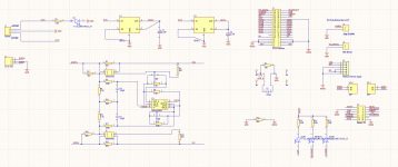
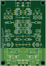
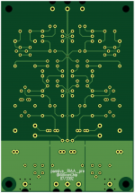
I am currently in the process of designing buffer board for purifi/nc500 modules. Any feedback on the schematic is appreciated.
Will share layout once I have it.
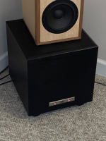
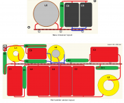
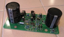
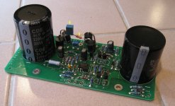
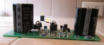
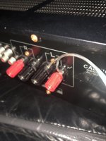
The HT sub started to act crazy, it would work ok for a couple of hours, but then the bass would eventually disappear.
I pulled the amp out and noticed a pair of caps were swollen, replaced them easily with the same value and it started working again.
That was encouraging but soon noticed the transformer was getting hot, very hot and this plate amp wasn't even back in the enclosure; which is a sealed plastic box inside the speaker box. I left it out on purpose just in case of something like this.
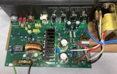
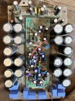
Not a lot of components on the plate amp, and they all look in good shape.
Since the plate amp is not in the box, I didn't reconnect the LEDs - Con3a1
I want to replace the tantalums as the Mr. Pass has suggested in some other topics discussing Threshold products.
In particular this amplifier has 2x 47uf/20v tantalum caps at the power stage, 1x 47uf/20v tantalum coupling cap at the line stage and not-sure-what-that-part-does stage 220uf/10v.
My plan is to use some well known caps such as elna silmic 2 but I am wondering if I can swap the input coupling cap for a better one - polypropylene film cap. 47uf film caps are really expensive, I wonder if I can replace it with lower nominal caps... For instance it does not have to be rated for such high voltage - 20v. If I am going to solder in a bipolar cap. I could do with 5v max - as far as I know the amp input sensitivity is bellow 2 volts.
What about its capacitance? My almost-non-existant electronics knowledge tells me that a cap and the input impedance form a high pass filter. I am not entirely sure what's the input impedance, but on some booklet I've seen it stating 75k. Hell, I believe we can agree that 10k would be the absolute minimum. With a 10k input impedance and 10 times lower capacitance 4.7uf cap I will have an f3 of ~4hz. And in case the impedance is actually 75k, f3 is even lower.
I am wondering if all this my rambling make any sense about swapping the input capacitor for a lower value polypropylene capacitor instead of maintaining the same nominal 47uf electrolytic.
Do you think it is safe to conduct this experiment in practice?
Thanks!
Richard Marsh Headphone amp Kit by TechDIY. Board and complete kit of parts including matched parts as recommended by Mr Marsh. This is a kit to build the amp boards themselves. Build/Info Thread
I will also provide the copy of Linear Audio article that I purchased.
Also, 4.17UV ultralow noise power supply regulator +-12/15V 1A from diyinhk. Link to shop
They have about 40hrs on them and are like new in the original packaging
Used to test an open baffle setup (which was great btw!). For people closeby the baffles are available free of charge (18mm baltic birch). Located in Eindhout, Belgium
What is your day to day listening Bluetooth Amplifier Setting up? I'm using TPA3116D2 Aiyima Amplifier Followed by BTD7170 Phillips Speakers.
I still wonder this Amps match with these speakers?
Just wonering is there any successful wHw diy build out there I can reference, I couldn't find one
I am looking at woof around 10 inch or 12 inch , and compression driver that can handle mid range to high freqency. Something look like GT sound or the traditional JBL speaker
Sunvalley adjustable equalization phono stage for sale; low hours. I bought this as a kit and assembled it but have decided to go another direction. A set of tubes will be included, not including a rectifier tube, but the pictured diode bridge will be included. Requires 120V wall voltage. I built this per spec except that I included some extra shielding around the head amp; this is easily removeable. This unit has the optional Vcap upgrade. Tube guards, which aren't in some of the pictures, will be included (I don't use them). Asking $1100; free shipping to the continental US, at cost elsewhere. This phono stage has fabulous reviews! Look them up!
Hope somebody can help.
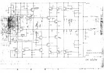
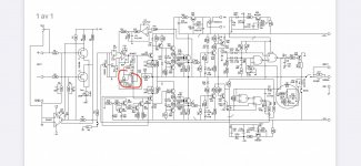
I have a Quad 303 which was faulty but i've fixed the fault ( open cct resistor on one of the driver boards ) and I intend to make 2 new amplifier boards and PSU board from scratch with HQ components throughout. Im puzzled by the schematic for the 303 and the actual board ? - The schematic shows 4 diodes around transistors tr103 and 104, but the actual amplifier has only 2 diodes ? I havent as yet verified why there are only 2 diodes fitted , but I will trace the tracks - any ideas what s going on with just the 2 diodes. Thanks . attached is a portion of the schematic im talking about
A new stereo mic based on a design I did many years ago, there are two electret mic capsules though they are very close together they are 180 degrees from each other and mounted on either side of a baffle so the stereo imagining isn't bad, the bottom part holds the output jack switch and battery. Login to view embedded media
Made some quick and crude H frames with a pair of 15” subwoofers with a QTS of .47 And an Fs of 21hz. Low passed at 140hz to some Dayton 3.5” fullrangers in sealed boxes and the sound is simply incredible!…..I’ve never had bass so articulate…..stand up acoustic bass is just amazing and cello?…….woah. If it gets any better than this, somebody share please. Didn’t take any measurements but I can tell I’m getting firm response to 35hz.
I am looking for a few baffle designs to improve diffraction. Troels has a few good designs which I posted below. Avalon Acoustic is another good example and looks good too.
What are some of baffle designs you have used in your design to improve diffraction?
Here is an example from Troels which I also use in for my speakers.
Somewhat easier to do but probably not quite optimized.
I have a cheap Bluetooth adapter so that I can play my phone or laptop music on an older stereo.
A couple FYI:
1. You can plug a wired headphones into this gadget, but the bass is weak, probably due to small output capacitors. This is not a problem driving high impedance stereo inputs.
2. It died and I suspected CMOS latch-up, so I momentarily shorted the internal battery and sure enough, it came back to life. https://i5.walmartimages.com/.../86b5cd16-24f3-4cd9-bfe9...
Hello friends! I have a schematic that a computer science professor designed for me (he doesn't know much about audio, he only works with computers). It is a system that goes between a Class D module and the output of an electric bass preamp, specifically an Ampeg SVP Pro, it has a volume and a control that mixes the output of both triodes.
The design sounds very good connected to a Class D Ice Power 125 ASX module, the triode used is a 6sn7 with modifiable filament voltage adjustment to be able to use 12sn7 as well. Unfortunately, the Professor is no longer with us (RIP) so I cannot ask him for help.
The problem with the design is that it distorts when an external Bass Preamp is connected to it, when there is too much signal, the whole distorts, not too much, but if the idea is to keep it as far away as possible, the important thing is a clean sound.
I am not an expert, but I do know how to read electronic schematics and draw them (although I still have a lot to learn)
Thank you very much. 🙂
I know a few things about damping factor but not enough... I know it makes your bass sound flabby, booooomy, slow, like it's getting in the way of the music that's coming because the damn woofer is still recovering. I know physically, bad damping is the amps inability to control the momentum of the speaker cone, to slow it when it needs slowing, right? So it's kind of like the brakes on a car?
Is bad damping factor caused because tubes are inherently easier to "turn on" than they are to "turn off" (non linear)? If tubes are slower to turn off than turn on I could see how that might make it better at making the speaker cone move than making the speaker cone slow down. Is that right? Or am I wrong on that. Some other fundamental cause?
What is the best method to improve damping factor in an amp design? And, how far can/should you take that method before you start to cause some other problem in the design, because everything is a compromise right.
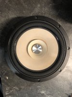
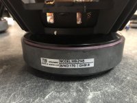
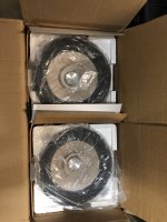
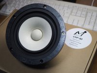
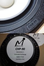
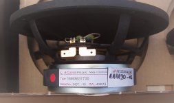
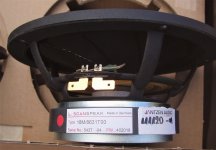
I recently stumbled upon a pair of Aurasound MR-12.4 subwoofers on eBay, new in box, for $300 including shipping. A fantastic price, I thought, for the NS12-794-4A's flamboyantly dressed twin.
I bought them, received them, and as promised, they were new in box. Unfortunately, all was not well with the subs.
Their coils were rubbing.
I removed the magnets and found that the plating on the neodymium magnets was bubbled on one, and bubbled/flaking on the other. I was able to remove the bad plating, but this left me with two problems:
1.) The magnets are neodymium/iron alloy. Without the plating, they will corrode/rust over time.
2.) The voice coil in one driver was scratched in several places by the flaking plating, resulting in shorting. Its coil reads 2.6 ohms instead of 3.5.
The seller was excellent about this, refunded me my money, and let me keep the subs. Needless to say, I want to try to repair them. So, I was hoping to do a little brainstorming with you all.
My initial ideas are to:
1.) Coat the exposed sides of the magnets with a high-heat primer, or maybe even a dielectric varnish to take care of any possible corrosion.
2.) Gently sand away the scratches on the damaged voice coil, and recoat it with varnish.
Anyone have any thoughts, concerns, or ideas? What would you try?
I have an issue with the mids and tweeters being too loud ..., they were part of another set-up and i use them and the original crossover " as is " on my own loudspeaker built . If I add series resistance won't this upset / lower the original crossover points .
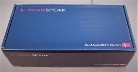
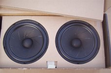
I have a pair of Scanspeck 18M/8631T00 Revelators for sale.
Purchased 12/2020 from Jantzan Audio for a high end diy speaker project. 11 months use.
Boxed.
Sold
Hello,
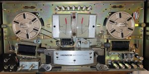
I have a Pioneer RT-707 I picked up today. You have to push up on the roller for the solenoid to retract and hold tension on the tape. Once it is up it is fine and holds tension. You can pause it and play again and it seems to function okay. I haven't connected it to an amp yet.The seller said the solenoid needs to be lubed. I took the cover off and I don't really see what he is talking about. The solenoid seems to be free in it's armature. Thank you
Edit: The pinch roller solenoid is moving very slowly. If it's about 1/2 way up it will pinch fast enough. It moves slowly when it retracts and when it releases. I cleaned the old grease off where I could see it and put new on and no change
Edit2: I cleaned the grease off I put on there and lubed all the moving parts (5) related to the pinch roller solenoid with a very small amount of 3in1 oil. It is working fine today. The two arms on the bottom are difficult to get oil in. A very tiny amount and let it sit face up over night.
Hi I am looking to buy a good book on speaker design and construction, and I am a beginner with regard to this subject, can anyone suggest any good books to buy on speaker theory, design, and construction. Ultimatley I would like the build an active 2 way speaker.
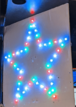
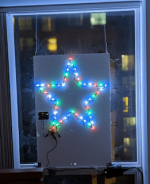
My Xmas start rises for every December. I found one on the WWW and created my own version with programmable LEDs, Arduino UNO, and a 5vdc, 6amp power supply. I don't like blinking LEDs. I prefer to issue a repeating red,green, blue pattern. Xmas decorations are not regulated ( and should not be) but some neighbors have a large inflatable Santa Claus that deflates in the morning.
please look at scheme below and give me your thoughts, all inputs will be appreciated. choice of parts were based on what is available, i want to utilise my jnukbox fully.
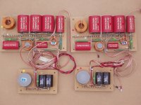
I have one set of assembled Troels crossovers for the Fusion project.
Kit supplied by Jantzen £898
Fully working as designed used for around 11 months.
Looking for £500 plus postage to UK only.
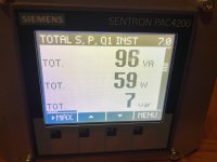
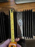
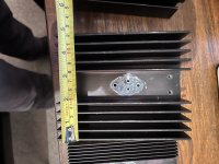
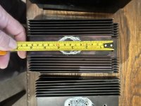
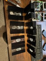
I recently bought a used D200i and I wonder if it’s been “tweaked” with.
It’s fully functional but cooling fins are basically room temperature. As they look like they can take some heat it makes me curious.
Measuring input power to <60W. Manual states 100W idle. I’ve asked Gamut without any answer.
I found a schematic online supposed to be for D200 ( not i) which is attached. The only thing to adjust seems to be for dc-offset or is it for something else?
I would really appreciate if someone has a D200i schematic to share. A service manual even better of course 😊
Our shop just re-capped the main filter caps in a vac 30 30 300b amp that now has a low hum. when the 6sn7 tubes are pulled, the hum is still there. I installed high quality, 105c, charged and tested caps.
do these amps have a low hum?
Get a 5 to 13 volt supply and a DC voltmeter. Connect the +V to the
Drain, connect the Gate and Source together to a 100 ohm resistor,
and connect the other lead of the resistor to ground.
Measure the voltage across the resistor, which gives the Idss. 1 volt
= 10 mA of current.
Try to measure all devices under the same conditions, temperature,
and duration of test.
Hi everyone .
I have never designed and used software to build speaker cabinet so I have to start from scratch.
I don't even know exactly what it takes. from what I have read, software to do simulations and software with microphone to record the response after building the cabinet with the speakers, so that corrections can be made if necessary.
I cannot waste much time studying the user manual and therefore I ask you to indicate the simplest and most intuitive software possible together with a cheap but decent quality microphone.
bye thank you
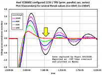
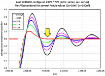
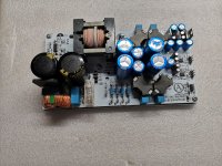
I thought other diyAudio members might be interested in the modification I made to my Akitika GT-101 power amp kit. I added a snubber on the Power Supply Unit PCBoard, to reduce/eliminate RF interference by damping out any transformer secondary ringing that may occur when the rectifier diodes turn off.
The GT-101's PSU board already includes capacitor C5 (0.01 uF) across the secondary; the snubber components I added are (0.15uF in series with 110 ohms) for 115VAC operation, or (0.15uF in series with 120 ohms) for 230VAC operation. These are shown in a dotted rectangle on the attached schematics, and are indicated by yellow arrows in the "After" photographs.
Measured scope waveforms using the "Quasimodo" test jig (link) are also attached. You can see that the transformer secondary is critically damped (zeta = 1.00) in the red traces, corresponding to 109 ohms and 120 ohms.
The GT-101 uses an Avel Lindberg Y236602 toroidal transformer. It is rated 230VA, has dual primaries for 115VAC / 230VAC operation, and dual 35V secondaries which the kit connects in series. This 70VAC is rectified, filtered, and then feeds a DC voltage regulator (rare in a chip amp) which applies +72VDC to the LM3886 ICs.
Hey all!
I have an old carver tfm-15 cb that is fried. The meters are still good, the transformer and power supply are still great but the amp board is cooked.
I'm thinking about gutting this thing and putting in a couple of Naim 140 boards. After some measurements it looks like it will fit with lots of room to spare. The heat sinks are plenty big enough and it should work out.
The question I have is about the transformer, the only literature I can find on the 140 boards is that it takes +/- 40 volts. My transformer puts out 40-0-40 and the psu bumps it up to 53-0-53 DC. Now I'm sure I'll have to replace the psu or at least tone it down. But does the Naim 140 take a rectified 40-0-40 or rectified 20-0-20?
can anyone help me out?
Thanks guys
mark H.
,
I am selling this amplifier. It was purchased for a project that I postponed and was only briefly tested. Price is 100 € + shipping costs 20€ - payment via Paypal - only EU
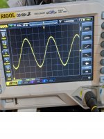
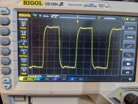
There is so much information online but I'm completely lost! I took a couple of pictures of some wave forms I'm trying to understand. The are from a cd player with 11.2896mhz. Which is better? Any help appreciated
Hi,
I am working on rebuilding the musical fidelity MA50, same circuit as A1 with higher rail voltage.
After my rebuild, one channel is good, but the other channel suffered from distortion problem about 10 seconds after power on. I measured the voltages, found the problem the problem could be abnormal voltage drop on R5.
As the schematics shows, r5 connects to emitter leg of TR1 and TR2. It measures about only 250mv and quickly dropped to 200mv or less. Compare to the other working channel, the voltage should be around 500-580mv. Voltage on R12 in the same channel voltage looks goods.
So I think the problem is bottom half of the circuit.
I think R5 voltage problem affected the wrong voltages on entire bottom half of transistors ( TR5, 6, 9)
I believe this is the source of the distortion.
My question is what determines the R5-TR1,2 voltage?
I measured almost the entire circuit check for wrong elements and connections, but can not find anything wrong. So I think its better to do some theoretical analysis based on what I found.
I'm making a guitar "pedal power amp" as a bit of an experiment after years of making Bluetooth speakers using the commonly available eBay class D boards.
For this project I'm looking at this XH-M542 board:
I know it says 100w, and it likely isn't, but that doesn't matter. As long as I can get say 30w at least from a 24v/3a PSU, it'll be fine.
My first conundrum was adding a volume control. I can't remember which thread I read on here, but I arrived at a simple 10k log pot on the input. I think that was chosen as the input impedance of the amp is also 10k? I could be wrong.
My next hope is to be able to add a couple of extra switches to the pedal to give a couple more sound options.
I'm thinking a bass cut switch to roll off some low end and tighten up the sound a bit, and then a bright switch that allows some treble to pass the volume control when the volume is turned down. These are also called "treble bleed" circuits and are found on guitar volume controls a lot, as you may know.
So my question is what values will the components required need to be, and how they will be connected up in relation to the volume control.
I have a Sota that I am rebuilding, and got a new motor, controller and sub chassis spring kit.
Plus a new arm and arm board, and cart.
So I now have an old motor, and wall wort.
An old arm, and an old cart.
If I can find a bearing assembly that would be great. A magnetic levitation one would be even better.
Where does one find a source for this stuff?
(The ClearAudio importer said that they will not sell an upgrade MagLev spindle without a trade in of the old part.)
Basiically I want a TT for the shed or give to one of the kiddies.
I have access to a lathe to make a platter, so I can make it fit whatever bearing I might stumble upon..
What happens if I connect a 100w tweeter and a 5000w subwoofer to a passive crossover and turn the volume of the amplifier to it's power that's above 600w.
Will the tweeter blow?
Should I match the power of both tweeter and subwoofer to avoid this?
In all the on line calculators a passive24 dB high pass filter can be seen as two 12 dB serie filter and is always made the same way: first serie cap is always the littliest capacitance value then the second "hub" (cellule) has a bigger capacitance value.
Is there a reason why a designer may want to invert the two 12 dB "hubs" of a 24 dB filter by putting first the bigger capacitance value with its dedicated shunt voice-coil then the second "hub" that is usualy the first ?
A sim on a crossover filter soft is saying that is the same but is it ? Or there is reason to invert sometimes ? Parts precision after sorting out vis a vis of the low pass filter for instance, anything else ?
Hi all, audio newbie here looking for advice. I've found this forum to be genuinely helpful.
I want very good speakers for my gaming PC. I will also use my PC to stream netflix/music. I was planning on getting some sort of DAC device. Some helpful people here previously recommended active speakers (i.e., JBL LSR305). I'm open to those.
Another audio friend of mine recommended the Rotel A11 Tribute (link here). It's an integrated amplifier that goes for $800. Not cheap. I can afford it, but don't want to invest money in something I won't notice a major difference in. I'm not an audiophile, but want good sound for years to come.
I watched this youtube video by the cheapaudioman which listed numerous high quality speakers. Among them were the Sony SSCS5 (link here). The consensus seems to be that they are surprisingly great for their price point. My understanding is that these are passive speakers.
My audio friend said that having this amplifier will enhance the quality of the sound. My question is: by how much?
To summarize: Will I notice a major difference between a Rotel A11 Tribute with good passive speakers (i.e., Sony SSCS5) versus a good pair of powered speakers like the JBL LSR305? I would use some sort of USB DAC device with my PC for either of tehse.
I'm not an audiophile that can outline the pros and cons of what the amplifier adds. In other words, here am I considering spending $800 on a device that I don't know much about, and it's magnitudes higher in price than the speakers I'm interested in. This is why I wanted to hear from you guys regarding the value added by an amplifier.
mids treble will again be PR170mo/Rt2ha
1st order xo, points around 300hz/1500hz
Woofer requirements: a honest 98db efficiency, smooth roll off, no 10db peak at 1.2khz please!
Hi,
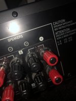
I’ve had this turntable set up for a few years now and have recently ran into an issue I can’t seem to fix. The left speaker ports on two separate amps have started playing flawed audio whenever I plug them in. I know the issue isnt the cables or the speakers because they play perfect when I switch them to the right port. I also don’t think it’s the amps because I find it unlikely that the same port on two amps have suddenly stopped working properly.
I am looking for some kind soul to advise on a suspect valve. To me it looks like heater is failing still working but I am not risking it. I dont want to have it fail and cause other probs. Right hand valve toasty on one filament.... On switch on there is a disconcerting spark (seemingly from valse but its so quick hard to tell). One filament is clearly heating but others not. I guess its time to replace (it is only 8 months old and light usage!). The valve circuit must be complete for it to light up at all so I guess there is a short of some sort. My instinct is just to replace (again). Am I right to just bin it?
Combined broadband volume diffusor and bass absorber
To be of real practical use, diffusers are wanted efficient over a broad frequency range and bass absorbers should (usually / often) only be wanted efficient in the low range. Mid and high frequencies are wanted scattered / diffused in the room, not absorbed creating a “dead sounding room”. A combination will require large width and depth. That combination can be accomplished with volumetric diffusers integrated into a deep bass absorber. If one has a long room and can spare the depth needed, both low bass modes can be treated while having a diffused “live” sound for mids and high frequencies. If one uses surround speakers / subs at the back wall, these can be integrated too.
In a document for Degree of Doctor of Philosophy at Salford University’s faculty for acoustics, Richard James Hughes presents his findings för Volume Diffusers in comparison to other type of diffusers like BAD, Schroeder, MLS etc. In short, the volume ones show better results. The paper is loaded with heavy math but it is not necessary to understand all that math, one gets by quite well from the text alone and the diagrams. The original paper is included and a “compilation” I made. In the paper "Geometric Shadow Zone and Back Scattering" is mentioned with a bunch of math. In the compilation some pictures for this is included. BADs aim for 50% reflecting areas and 50% absorbtive areas. Volume diffusers are based on a Golomb Ruler (google for explanation) and like BADs aim for a total of 50% reflecting area but for for 50% transparency (gaps between slats), seen from straight ahead. BADs have no temporal diffusion, volume diffusers have that. A bunch of identical Schroeder diffusers beside each other, forming a long total width, will give lobing. There will be no/less of lobing with volume diffusers. In short the volume diffuser consist of, say 5 layers / fences, behind each other. Each fence has a different slat width, narrowest at the front and widest at the back.
Negative about broadband volume diffusers with several layers:
They need to be large in length and depth.
Positive about broadband volume diffusers with several layers:
As they need to be large in length and deep, they are suitable to integrate with efficient bass absorbers and back wall speakers.
They are a lot easier / less time consuming to DIY with fewer and simple tools than say BADs, Schroeder or “skyline” diffusers.
If one wants to, one can integrate LED-strips for visual effects behind the slats.
Hughes gives a nice example for the construction of a complete volume diffuser to reach the wanted 50 % transparency and which has a broad range from 400 to 3378 Hz. I took that example and wrote an excel spread sheet from it. From the excel, one can to a certain amount customize other widths. Ideally: Start with total possible width, the 2 slats at the back should together form 1/3 of the diffuser width. Then keep the width ratios in the excel from back to front intact to keep 50% transparency. Check out carefully on the “drawing” where the slat should be positioned for 50% transparency. Example there are 3 slat 180 mm wide versus totalt width 1800 mm. It is quite easy to count 3x180 mm slats and 3 gaps with w= 180mm. As the chosen “N” = 10 x 180 mm = 1800 mm, it is easy to conclude that the largest gap in that “fence” is then 10-6 = 4x180 mm wide. One can chose other “N” depending on available width and depth. That will be a compromise and change the 50% transparency. If available width is small, the slats at the front will be very narrow with 5 “fences”. Diffusion at very high frequencies is quite useless unless you are a dog or a bat. I would use fewer fences in that case and skip the first at the front.
From some scrap wood I made some which are 70 cm wide x 30 cm deep x 120 cm high. I put some hinges on them so they can be swiveled sideways to have some control of where to steer the reflection in the room, towards listening position or towards side wall for longer delay time. (70 cm was a bit too wide, so I had to cut off a corner for a clearance vs the sub.)
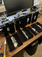
A bunch of Philips, Rata , Ansar capacitors that all test at correct levels or very close .
Needless to say that I’m giving these away for someone to make use of and not just list for sale ( I could do that)
I will also throw in a bunch of induction coils and maybe more stuff like crimson audio boards etc.
Amongst other ideas spinning round in my head i had a thought about machining the last part of the spindle and replacing it with panzerholz for damping.
The new part would be tapped and the existing spindle threaded.
what do you guys think?
im trying to figure out what impact the clocks of the raspberry pi 4 have and i wanna exchange them but i need a little help since im not too keen on electronics
but im kinda wondering which would be the better approach
1. one 10mhz oxco master clock where the 25mhz and 54mhz clock signal are derived from for the raspberry pi
2. or seperat 25mhz/54mhz txco clocks
and im curious if i even need one of those boards, would it be easy to implement two txco clocks just by myself? do i even need additonal circuitry or can i power one of those txco clocks directly with 3,3 and just hook up the output to the clock input pad on the raspberry pi after i removed the existing clock? i actually dont think there is much needed circuitry wise beside maybe a few caps?
any help is much appreciated (as long it isnt "this doesnt matter" advice, i wanna test it myself 🙂 )
Hi, I was looking for some documentation on a kit I got ahold of, the GB150D by Greg Ball.
Greg has closed down his online forum and thus removed the documentation, he also released the designs to the DIY comunity.
Or so I understand.
I got in contact with one of Gregs former coworkers and he scanned the documentation for the power amplifier "GB150D" and the pre amplifier "SKpre".
He is getting old and his health is deteriorating, so he asked me to see to it that those who need the documentation gets it.
He also assured me that Greg himself doesn't care.
I attached the documentation but bare in mind that the pages are not all in order and there could be a page or two missing.
Hello Just bought me a new digital speaker management box (Marani Dpa 480)
My networkplayer have both analog balanced out and spdif out. I am planning to use the spdif.
Spdif is 75 ohm and aes is 110 ohm.
Can i use a 75 ohm cable without trouble or do i need som transformer feks this ?
I'm planning to move my music-playing system from a failing laptop to a virtual machine instead. The exact configuration is yet to be decided, but the host system will be Linux running either QEMU/KVM or VirtualBox. The guest OS would 'preferably' be also Linux.. there are a few excellent windows applications that continually tempt me, so that might still be an option, but just personally I'm not keen on where windows is headed so am trying to get up to speed on Linux instead.
The output will be to a DAC or high-quality external sound-card (there is the option of an internal card but I've had bad experiences of noise when the analogue section is within a full-blown PC). It will probably be multi-channel, even though I only play stereo, in order to allow digital-software crossovers.
Anyway, I've not tried to run serious quality audio from within a virtual machine before, so am quite naive about it. It might be a complete non-issue, or conversely there could be all sorts of pitfalls that I'm not aware of - as the audio is sent from within to without. So please forgive my ignorance and if anyone has experience of this I'd appreciate any thoughts on what problems might be encountered or what measures might need to be taken (if any) etc.
Since I am very interested in this design and it's hard to pick out the posts concerning this design in the other BIB thread I thought I would start a thread exclusively for the iBIBk.
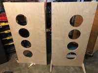
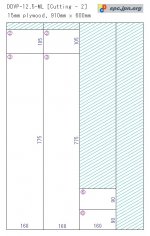
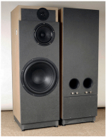
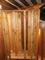
I'm currently using open baffles with 1 MarkAudio Alpair 12P and 2 Eminence Alpha 15a per side. The chipboard (these "prototypes" ended up serving me well for more than 2 years) was cut to closely mimic the dimensions of the Quad ESL. Add a MiniDSP and a pair of Quad 306: I like what I hear. Problem is depicted in image no. 3: They take up way too much space in my new, much smaller living room. 🙁
Since I already have and like the Alpair 12P, I thought about placing the woofers in storage and go with Scott's "Small Reflex" proposal. Hope it's OK to add the PDF. As far as I know it's been released to the DIY community, but somewhat hard to find on the web. Trouble is, nobody seems to use them. No matter if searching here or through Google, almost all results for Alpair 12P Small Reflex seem to refer to Abszero'sbuild or his own blogentries about it. The only other (modified) build I found is that by shane h and his brother. I reckon the 12P is not loved by everybody here and in particular the low-end extension is not exactly its strong point, but is the Small Reflex really that bad? If anybody has build them silently and in secret, please stand up and share your experience.
Strictly speaking, a 12P Pensil is taking up about the same space as the Small Reflex on its stands. But as alternative facts have become so popular lately, I have to say that the visual appearance is still heftier. Also the Pensil does not fit into my car, while the Small Reflex does. 😛
As far as cabinet construction goes: I'm tempted by the idea to go with 18mm plywood for the baffle and back only and make the other walls from 15mm or even 12mm plywood. With addition of one vertical and two horizontal braces (12mm ?) I feel like this could still be stiff enough compared to the small panel sizes to deal with. What do you think?
Thankful for any thoughts and comments. Even if it ends up to be "just try it yourself" or "go with SuperPensils" or "ditch all your lowly equipment".
Good night (for these latitudes).
I bought an IFI ZEN PHONO phono preamplifier based on good recommendations on the internet.
Compared to other preamplifiers I have, some highly commented DIYs on DIYAUDIO and others like Project phono box; and the one built into my Marantz PM6006 amp, this IFI seems to me to be better in many ways.
But I notice low gain in the MM position (36 dB).
That is why I want to make a x2 or x3 line preamplifier with the SSM2019 IC in order to achieve some gain and at the same time take advantage of the balanced outputs that the pre IFI has.
I already have the IC SSM2019 since I had built the SOLIDPHONO phono pre from TNT magazine.
Is it possible to do what I have planned?
Can I take advantage of the balanced output of the IFI in this way?
Thanks.
I am trying to track down a schematic for Greg Ball's SKA SKPre (preamp) and the SKOptivol module that works with it. I've searched the web to the best of my ability but keep getting to a dead end. Any help will be appreciated. I believe Greg is out of touch these days but if anyone knows how to contact him, perhaps that would help. Thanks.
Can anyone suggest a compact, affordable line buffer for my 100as2 boards (1.8k input impedance!) To allow me to use a regular log pot volume control.
I need 8 channels worth, so something like a b1 for every channel would obliterate my bank account.
I'm pretty new to the non speaker side of DIY audio, so pre-populated pcb's would be ideal, but I can solder up some boards as long as there's no tiny surface mount bits.
Can anyone advise at things I should be looking at, matching power supplies would be awesome too!
Hi Folks,
its the first time I wrote in diyAudio. And this is my inquiry . Is anyone out there who got the AC/ Audio levels values for the MC-3500 schematic. I found two schematics in the net , but they got only the DC values on it.
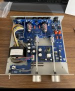
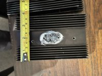
I was wondering if someone here might be able to assist with identifying the make and series (or type) of film capacitor that is used in the attached photo. The manufacturer of this device offers an upgrade to Evox capacitors but doesn't specify the series or type. I'm hoping that if I can establish more about the stock caps it will help me narrow down which Evox caps they use in the upgrade. So far I have not been able to get any internal pix of a unit with the "Evox upgrade", however at least one of their other products uses blue film caps that I suspect are Evox PFR. I can't justify paying for the cost of the upgrade when I know it's only a few $ of caps I can swap out myself.
Anyone have an opinion as to suitability of these Vishay MKP1839 caps when used as coupling caps both between stages or at the output of a pre-amp? https://www.vishay.com/docs/26022/mkp1839.pdf
Anything particularly good or bad stand out?
TIA
I need to make a 550 to 600 litre box as a test and locally I can get 1800 * 600 sheets of chipboard for $23 each but they are only 12mm thick.
3 sheets with a fourth for top and bottom make an enclosure that is close to 600 litres
A few of questions.
What's the easiest and cheapest way to get such a large box square and true?
What's the cheapest way to stiffen and deaden cheap chipboard?
I have some long and narrow scraps of MDF here but they are only 6mm thick
If the box works I can always add another layer of something on the outside.
I thought I could use chipboard flooring for the front baffle as it is both thicker and denser but it is a bit outside the budget for a test box
So where to begin...
Got this 3225PE free after it was damaged in transit and decided that it was worth saving but starting to having second thoughts now.
Long story made short, fixed the original fault (R437/R453/Q409/Q411/Q413/Q415/Q417 and Q401).
After setting idle current and offset (in both channels) and everything running sweet I power it down and proceeded to solder the 2 bridges that short the 1 Ohm resistors ( R455/R456 ) I had a very small spark on the Right channel R546 - 1 ohm resistor and after powering up I had 28Vdc on the output again ( original fault on the left channel)
After many checks found the new MJ2955 shorted but nothing else ( I checked every single active and passive component on that channel) and by checking I mean out of the circuit board.
So I powered it up again with in line light bulb protection and it worked but when I try to set up idle current for that channel I get over 30Vdc on the 1 Ohm resistor instead of the 25/30mV but output offset is normal at around 30mV
My problem is that I can't find any defective component, can't adjust idle current and I'm running out of talent...
Help please.
As a long time lurker and stupid question poser I thought I'd better put my £ where my mouth is.
So here are my Satorels.
SB SATori WO24P-4, mOREL Em1308 and ET448, xovers are with a Minidsp Nanodigi.
There is a load of info in the linked pictures but basically the aim was to have a xover scheme (active) that was as simple as possible with limited EQ so that I could try and replicate in passive components in the future.
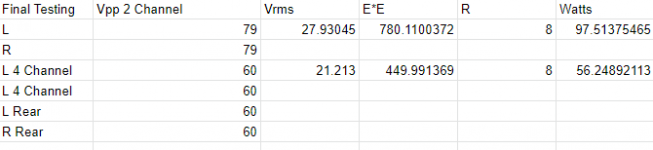
Caveat - measurements are in a small 9ft x 9ft room that has horrible reflections (below 300hz) so I did my best. Measurements taken with REW and Behringer UMC2002HD and ECM8000 (generic calibration file) at 85cm from baffle on centre line and at Tweeter height. Note dB scale is only indicative as I did not calibrate this but it was at the loud end of normal listening. I did try a spinorama for each driver but they were not good due to the room. A quick check showed good correlation with manufacturer data.
Xovers are - Woofer LR24 > Mid BW18 at approx 700hz and Mid LR24 > Tweeter LR24 at approx 3200hz, small notch in the woofer to cover baffle step and tweeter to save very high end. And that's it (plus delays and some gain adjustment).
The result is a pretty flat response with fairly low distortion at loud listening levels and I am getting a small amount of reverse nulls (probably room issues), not sure about the step response though.
I also knocked up some shaping curves to see which I likes most and will listen to these over the coming few weeks and decide which I like. I would also like to do a nominally 2nd order crossover to see what the difference is (with similar crossover points and flat response).
So, will now don my flack jacket and tin hat as I am very happy to have comments made as to what's good (hopefully) and what can be improved.
Raw driver measurements - Note protection capacitors on Mid 39uF and tweeter 12uF (also BW48 filters at 200hz and 700hz for protection)
Step response to develop delay - no idea if this is the correct methoid but seemed to work - result approx 0.3-0.4ms
Filters used in Mindsp and frequency response, distortion and full system Step response (not sure this look particularly good, comments please).
Shaping Filters and response
Manufacturer data checks (noting baffle step and room on Woofoer, a buit of diffraction and protection capacitor on mid, and I may have left a filter on for the tweeter, Doh ???)
..a friend ask me for a light PHONO-stage tunig on an Marantz 2245..
This is Number 3.
Origins: SiliconChip #07/2003, Sam YOSHIOKA.
..still beta-state.
NO! functionable Prototype..NO simulation, if anyone is interestet in, please do so.
We’re moving into a new house shortly and I have been thinking about subwoofer options, mainly for music (unfortunately I listen to a lot of pipe organ…)
Just wondering if anyone has ever tried a combination of Ripole style IB subwoofer, where the drivers are mounted in the ceiling, the slot between the drivers fires down into the room through the ceiling, and the back of the drivers fires into the ceiling space?
The ceiling is of timber joist/ sheet rock construction, and the face to face nature of the Ripole type construction would be force/vibration cancelling. This should reduce vibration issues. Hopefully the combined Fs will also end up lower than the driver spec although I’m not certain about this.
The back wave would naturally also be separated from the front wave - what is there not to like?
I’d anticipate using inexpensive pro drivers with paper cones and cloth surrounds to hopefully be resilient to the potentially high temperatures in the ceilings. I’d also anticipate using between two and four pairs of woofers to make the response throughout the room more uniform, although positioning is going to be next to impossible to test…
Woofer sizes I’d anticipate being between 12” and 18”.
MiniDSP would be used on the front end for XO/EQ.
I do currently have a pair of 12” Rythmik subs which are I love, but I’m thinking about trying to hide subwoofers entirely…
Does the Hi-Fi rack or mounting system have an effect on Hi-Fi performance? I have read some puzzling reviews in which the rack itself is promoted as being responsible for clearer sound or better definition.
Does damping out minute vibrations matter to quality of say a CD player?


 If anybody has build them silently and in secret, please stand up and share your experience.
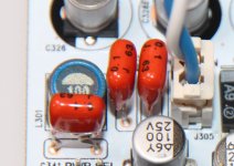


