A copy of Garry Pimm's Web Site

Hi,

Anyone have a complete copy of Garry Pimm's DIY web site?
Tried to download it from web.archive.org, but this backup is far from complete and much of stuff is being lost.
I have my own server so its not a problem to host a site of whatever meaningful size.

PS. Uploaded copy of Patrick Turner's site to my http://www.vacuum-tube.eu, red link from the front page (URL of a copy may change in the future because of site engine redesign, so please don't bookmark a link, only web site).

Code:
wget \
     --recursive \
     --no-clobber \
     --page-requisites \
     --html-extension \
     --convert-links \
     --restrict-file-names=windows \
     --timeout=5 --waitretry=0 --tries=3 --retry-connrefused \
     --domains web.archive.org \
     --no-parent \
         http://web.archive.org/web/20090416222321/http://www.pacifier.com/~gpimm

High Sensitivity HomeTheater Speaker Ideas?

Hi all,

I'm thinking of replacing my current commercial speakers, nothing special, but have been in service for over 10 years now, with a fun DIY project that also serves as an upgrade. They will be all three the same speaker ultimately to be the front main stage left, right and center, all three are vertical. No limit on size or weight. I'm happy with towers and I like to see them. But these will likely hide behind an acoustically transparent screen, but still, I will likely use birch and stain them.

I don't need them to do full range as I will crossover around 80hz maybe even down to 60hz depending on the speaker build, to the subs.

My main focus is to build something highly sensitive and efficient to take advantage of dynamic range and push them on peanuts of power, such as directly powered from a typical AVR. So I was mainly thinking of some larger sensitive woofers in the 12" range with 94~96db sensitivity and crossing over to a highly sensitive AMT ribbon tweeter or possibly a horn/compression driver. A 2 way should likely be fine as they will crossover with subs. I've never built a highly sensitive speaker before, so I'm curious what are some of the more popular options out there for folk doing this kind of thing. I would much rather spend to get high sensitivity now than to build lower and have to spend on more power down the road. Distance to seating will be anywhere from 12 to 16 feet max, so I'm just shooting for 105db peaks at 16 feet I think. I may not be able to get that on an AVR's power output, without resorting to extremely high sensitivity speakers like the 1099's or similar. But if I can at least get into the 100db range at 16 feet on AVR typical output's as peaks (obviously much lower when not transient peak) that would be great. If I absolutely have to just switch to using external amplification then I will. But for now I'd like to explore being able to potentially build sensitive enough speakers for an AVR to handle, if possible.

So two potential pathways, one being a 60hz to 20khz two way. The other being a 80hz to 20khz two way. I think it will be easier to do the 80hz and up option. But I'm curious if it's possible to get down to 60hz and be very efficient still.

Any obvious choices out there that are common from a driver perspective for this project?

I keep tossing between AMT/ribbons vs dome tweeters vs horn/compression driver options for the sake of horizontal dispersion. For stereo I would lean towards domes. But for home theater since there are lots of channels and more seats, I'm thinking of AMT/ribbons for the wider horizontal dispersion. I've just never built with one before.

Very best,
  • Like
Reactions: camplo

USB B on PC?

Hi, probably an impossibility, but here goes. I have a Volumio Primo streamer that outputs digital audio on a USB (A) port, the flat one. I want to connect that to a PC to do some DSP before going to a DAC.
But a regular USB cable has the USB B (the squarish one) at the output side of the cable, and a PC doesn't have such an input, as far as I know. Is there a way to do what I want?

Tia for any pointers,

Jan

AE Dimmerstat 8 D-1F Variac

Hi, i'm looking for a piece of ferrite that could fit into the bottom of varying output arm.
I contacted AE Dimmerstat in India, and they want to charge a fortune for a small piece of ferrite.
Ferrite is indicated with the yellow arrow with text to the right side

Attachments

  • AE Dimmerstat Label.jpg
    AE Dimmerstat Label.jpg
    298.4 KB · Views: 161
  • AE Dimmerstat Brush.jpg
    AE Dimmerstat Brush.jpg
    118.4 KB · Views: 119

Assistance in creating a ground in the trunk

Hi,
I used to have a screw that held down a few speaker ring terminals, acting as a ground in the trunk.
I needed some advice on how to secure a better ground in the trunk, ideally utilizing the existing hole, as the cables are cut to length.
I cannot access the other side as it appears to be in the wheel well.
The existing screw doesn't fully tighten.
It's the hole on the left that i used.

Attachments

  • Resized_20221115_092002.jpeg
    Resized_20221115_092002.jpeg
    288.6 KB · Views: 132

FS: HiVi DMB-A dome tweeters, pair

2” dome tweeters, like new, used in an experimental three way for a very short time.
$30 for the pair plus shipping from 28901.
Peter

Attachments

  • 9B2B0A11-6B9D-46DC-8BE9-E98E447B703A.jpeg
    9B2B0A11-6B9D-46DC-8BE9-E98E447B703A.jpeg
    533.1 KB · Views: 145
  • F3B3AFC8-1F02-4F89-9F08-3D38C29DEB14.jpeg
    F3B3AFC8-1F02-4F89-9F08-3D38C29DEB14.jpeg
    618.7 KB · Views: 134
  • D429DF42-CC2D-4968-8550-A17E0EA6F5A6.jpeg
    D429DF42-CC2D-4968-8550-A17E0EA6F5A6.jpeg
    336.8 KB · Views: 146
  • 98D64D07-6897-4FD1-A5F0-50CCC59C3948.jpeg
    98D64D07-6897-4FD1-A5F0-50CCC59C3948.jpeg
    556.5 KB · Views: 158

Vishay z-foil resistors - major sticker shock

so I just picked up a used wyred for sound preamp, and the mfg offers an upgrade of 24 Vishay z-foil resistors. so I say to myself, I'm a DIYer, I can do this myself.

but then.... digikey sells them, for something like $20 EACH. $20 for 1 resistor. this is digikey, not some boutique high end audio store.

I've never heard of anything so outrageous. (except prices for boutique cables)

New Amp - GU-50 Triode w 6N1P Cascode driver - Seeking advice

Hi, I'm interested in putting a new amp together. I've been accumulating old Soviet tubes via sellers in Ukraine and it's time to heat some of them up. In addition to the more common "guitar amp" tubes, I've picked up some oddballs like the GU-50, G-807 and its pal the 6P7S, many 6N1P, 6N2P, 6N6P noval tubes, as well as the octal preamp 6N8S (6SN7) and the 6N9S (6SL7) tubes. I would like to learn more about designing Single-Ended amplifiers and gain a more thorough understanding of preamp/driver stages.

So, based on some ideas about the GU-50 as a "Poor Man's 300b" I've hacked up a popular schematic for a 300b SET amplifier, and jammed the GU-50 in there:

6N1P-GU-50-Single-Ended-Tube-Amp-Schematic.jpg


Creating an Operating Point of 400v, 83mA with a 5K load calls for a 680ohm Cathode resistor, resulting in -56v btw Grid and Cathode according to this Vtaidy chart:

Screenshot (43).png


And while I can't test these tubes myself, one batch came with a hand-written note indicating the tubes had been tested at 400v on the plate, -60v on G1, with G2 and G3 connected to the plate, each tube had a value from 80-100mA written on the cap, so I feel confident powering the power tubes in this way.

Login to view embedded media
So, how do I determine the required drive signal for this power tube, and how do I increase the line level signal from my audio source (DAC or Phono pre) enough to do that? The schematic shown uses 2 gain stages, both sides of a 6SN7. Could I use the 6N1P in the same circuit? I I can easily find data on the 6SN7 as a resistance-coupled amplifier, but the data for the 6N1P is a little harder to come by. Any advice on how to proceed is welcome, thanks for taking a look.

Eico HF87 Rebuild, current source question

Greetings,

I'm rebuilding a HF87 to a configuration I put together back in the late 70's with the 6SN7 configured as a differential phase splitter. I'll followup this post with more on the history of the amp, but for now the question is what to use for a constant current source on the tail of the 6SN7 differential pair. I used a zener/NPN pair previously (schematic below), but was wondering if there's a better way to do this.


IMG_7477.jpg

Rotel + BHC Aerovox 10000uF 63V... worthwhile change?

I have a Rotel RB-870BX 100W power amp that is approximately 20 years old.
I can't find hardly any information on the 4 big 10000uF 63V capacitors that are in the unit... I originally misread them as 'Tawa' but now I've looked closer and noticed it's Towa which a Google later turned up as Fujitsu Towa.

3424785880_a283ca856f.jpg


Anyhow, I've been tinkering with the idea of replacing these 4 caps with something newer and perhaps better...

Obviously there are Nichicon KG Gold Tunes out there which seem like the ultimate, albeit with the price to go with it. Watching some on eBay, will see what happens.

JAPAN NICHICON KG audio Gold Tune 10000uF 63V 1PCS

But I've also had in my watch list for a long while these Aerovox caps which aren't too expensive (£30 for the 4 including postage from Hong Kong...:cannotbe: at current exchange rates) and I'm wondering, well is it worth changing the current caps for these?

Aerovox BHC Electrolytic Capacitor 10000uF / 63V

What are the benefits? Anyone had experience or knowledge with Towa capacitors? Other than the unit being 20 years old everything seems to work as it should just now if that should make any bearing on my decision to do the work (you know us modders, we just can't stop tinkering!!!)

829B tubes for audio?

Hi out there.

Recently i was offered some NOS RCA 829B tubes. It is a dual beam pover tube. Data comparable to kt88. I searched the net for some posible audio use and found that Cayin uses the tube in som rather nice looking amps. http://www.cayin.com/ (check the cayin 800MK) Has anny of you used this tube? I was thinking of building an pp triode amp inspired of the PP-1 amp http://www.vacuumstate.com/images/PP-1C_a.gif Anny coments on that. Anny advice is welcome.

Thanks Peter Jensen😎

SB Acoustics SB65WBAC25-4 - What to do?

I now have a pair of these really cute 2.5in drivers - they seem to have some nice specifications on paper. They look very well made and superb fit and finish - I am impressed by the quality from SB Acouatics. I have heard some great recommendations of this little guy - great HF extension almost aluminum dome tweeter like. Oh wait, it is about the size of an aluminum dome tweeter. 🙂

The neat thing is that with an xmax of 5.3mm and a moderate Qts, it can reach sub 100Hz in the right enclosure. Sure, if I run this in a FAST XO at 400Hz it would work very well. But given the huge xmax, I want to see what creative uses we can all come up with. Does anyone have experiences of good boxes that they have tried?

478303d1429445363-sb-acoustics-sb65wbac25-4-what-do-image.jpg


SB Acoustics :: 2 1/2" SB65WBAC25-4


My first thought is to make a small BLH for it. Maybe a hybrid BVR type BLH... Like a mini Decware DNA. 🙂

Attachments

  • image.jpg
    image.jpg
    87.3 KB · Views: 6,769

Help with 3-way PA system build and process (MTL-46 + MT-130)

Hi,

I'm looking to build a 3-way system for outdoor parties, with around 200 people, in Madeira island, PT.

The goal is to have a system with a hi-fi sound with PA characteristics. We mainly play vinil and the music is quite diverse. It can go from Ambient, Reggae and Disco to different styles of dance music like Acid, Electro and Jungle. So it's important for us that the system can play non-electronic music with detail and power.

Budget
5000€

So far I came across with the following solution for each stack:

2x Sub MTL-46
with RCF LF18G401
Would one sub be enough?

1x Mid-top MT-130
Precision Devices PD.121/2 8 Ohms
BMS 4554 8 Ohm
Eighteensound XT 1464
Are these drivers correct?

Crossover
What would be the best solution for crossover? A passive one inside the MT-130 and an active between the sub and the Mid-top? Could I do everything with a DBX DriveRack PA2 or a Behringer DCX2496?

Amp
I need 3 amplifiers. The power of each amp should be the same as the RMS of each driver? How do I balance the volume between the 3 drivers, on the amp or on a DSP?

EQ and final adjustments
After I have the speakers done, what kind of adjustments I need to do? Can someone help me with the process?

Sorry for such rookie questions but we all gotta start somewhere right? If someone is experienced enough and wants to help me with this within this budget I can happily pay for your work
:)


Thanks!

Attachments

Help with intermittent crackling noise in microphone preamp

Hi!

I'm turning to you for help finding a faulty component causing a "crackling" noise in a Presonus Studio Channel (Microphone preamp).
I've recorded the noise (link at the bottom) and my question is if any of you more experienced guys -based on the sound in the link- can give a good guess on what type of component is likley to cause this type of noise, if that even possible?
  • The noise emerges early in the circut (before the tube and input gain knob) and gets lounder/disappear when I turn the input pot.
  • It is not affected by any microphone connected/disconnected to the preamp
  • Sometimes it is audible directly on startup, other times it takes a few minutes before it appears.
  • It is not affected when I wiggle any components.
  • There are no visual indication of heat damage on any of the components, no bulging caps.
mp3 noise example »

What do you say? Does it point in any direction? Is it still likely to be a faulty cap? 🤔

Kartesian Acoustics Widebanders

Haven't seen much on these.

I recently bought a Wib100_vPA-S for testing and I'm quite impressed with it.

https://www.kartesian-acoustic.com/wib100-vpa-s

Handles a lot of power as a mid tweeter. Very clear neutral sound once the peak is taken care of. I think this would be a great candidate for a design like the LXmini.

Just wanted to throw my two cents in if anyone was curious about their quality. I'll probably try their highend model next.

AlNiCo magnet update

I get a lot of questions about the AlNiCo magnet Betsy's.

1. Yes, they sound much better than the standard Betsy.

2. They are still a "special" in that I don't typically stock them. More accurately, I can't source magnets fast enough to keep them in stock. There's currently both a trade war and a pandemic that is making this extremely difficult.

3. Email me at wildburroaudio using gmail.com and I can put you on the waiting list. The next batch of magnets could arrive Summer 2021.

4. Material costs are jumping all over. Prices will be going up for the next batch. I still see the AlNiCo Betsy as being a great value in comparison to other fullrange peers.

Best,

Douglas

Push pull transformer SPICE simulation from the spec

Let's take this one and for the moment put aside resistance, capacitance and leakage. The remaining spec:

Secondary Impedance4 and 8 Ω
Primary Impedance6,6 kΩ
Turns Ratio (Np:Ns)40,62:1(4Ω) , 28,72:1 (8Ω)
Primary Inductance Lp591 H

I assume the turns ratio and input impedance (corresponding to 8 Ohm load) are given relative to primary end points (cathode to cathode) (?). So the secondary inductance can be found as Ls = Lp*8/6600 and inductance of the one section of the primary would be Lp2 = Lp/4. Am I missing something?

Curved Baffles Lead to Narrower Beamwidth

While working on my current project I found that curving that baffle narrowed the beamwidth.

gTibaAW.jpg


This is counter-intuitive. When you look at baffle like this, I imagine that you would expect that this curvature would cause the sound to be scattered into a wider beam.

My measurements show that the *opposite* is the case: bending the baffle backwards NARROWS the beam, not broadens it.

Here's what I think is going on:

TMCgxn8.png


When you put a loudspeaker onto a flat baffle, the sound radiates into 180 degrees. Due to this, the sound off-axis is similar to the sound ON axis.

When you put a loudspeaker into a 90 degree waveguide, the sound is concentrated into a beam that's approximately 90 degrees wide. As long as the wavelengths are shorter than the waveguide, they will be louder than off-axis. Basically the conical waveguide is taking the energy radiated by the loudspeaker and it's concentrating it into a controlled beam. Because the same amount of energy is radiating into a narrower angle, it's louder when you're within it's beam.

The third case is a bit peculiar. If the wavelengths are shorter than the conical waveguide in the center, then the waves will largely behave as if they were radiating from a plain ol' conical waveguide.

Things get complex if the waves are as long as the baffle. This is because part of that wave (not the entire wave) is radiating into a larger angle.

For instance, let's say the baffle is 13.5" wide. The waveguide at the center of the baffle is 6.75" in diameter. If the wavelength is 2khz, then there's no issues, it is constrained by the waveguide in the center. (2khz is 6.75" long.)

But if the wavelength is 1khz, then the *center* of the wave is constrained, but the EDGES of the wave are radiating into a wider angle.

I believe that the net effect is that the edges of the wave are BENT and SHADED.

LAs.jpg

In concert venues, they do something very similar with arrays. They shape them into a "J" shape, and the elements at the bottom of the array are shaded. The idea is to reduce the volume going to the front of the room, with the intention of sending more sound to the BACK of the room than the front.

kefbladeone.jpg


If I am correct, then the shape of this baffle works on the same principle. The curvature at the edges is reducing the amount of sound that's radiated to the sidewalls.

OJkiOMK.jpg

Here is my current speaker project. I didn't curve the baffle because I'm A Galaxy Brain, I was just trying to make the box smaller. The change in beamwidth was accidental.

Af2fkIS.png


7q9Rq40.png


Here's the response of the loudspeaker with identical crossover, identical EQ settings, but one baffle is flat and 10.5" wide, while the other baffle is the one pictured above. IE, by extending the baffle an additional 8.5" and curving it back by 45 degrees, beamwidth control was extended a full octave.

Naturally, there's no free lunch:

1) the speaker is now radiating into a larger angle, and requires more power below 1000Hz

2) Curving the baffle backwards introduces peaks and dips into the response *above* 2khz

3) Curving the baffle backwards affects the consistency of the directivity above 2khz

In a nutshell, you'd want to use software to optimize the baffle shape *and* the waveguide shape. You can't just curve the baffle, you have to treat the whole thing as a single unit.

If I'm not mistaken, hornresp and Akabak can't simulate this, but axidriver and ABEC *can.*
  • Like
Reactions: jawen

Solutions to solve audio processing delay (ALSA/Linux)

Hi there,

The problem I am trying to solve is latency / audio delay for "lip sync" issues when playing video sources such as You Tube. That is - the video is ahead of the audio (so I need to either delay the video, or speed up audio).

I am constrained by the TV which only supports audio delay (I need video delay) and only for optical output.

I have a Raspberry Pi running Camilla DSP for an active crossover. This all works well.

Since the Pi (and Suptronics DAC) has no audio input, I have added a USB 5.1 soundcard - and using the line in (so I can connect to the TV). The Soundcard supports either RCA (analogue) line in or SPDIF

I need to loop the USB soundcard input - to the Camilla input device (currently using the loopback device loaded by snd-aloop).

I am using the alsaloop utility - with the lowest latency I can get away with without skipping complaints (50 usec) but the audio lag is still visible:

Code:
alsaloop -P dmix:1 -C hw:2,0 -S 5 -v -t 50000

The Camilla DSP source device is hw:Loopback,1 (dmix:1 above) and USB card is hw:2,0

I am using dmix since I want to have dual sources - both MPD playing locally stored audio AND "The TV" when I finally plug it in.

I have yet to try a simple arecord | aplay pipe (not at computer).

I do not have an A/V receiver with the smarts to do video buffering / delay.

I'm just wanting to know if I'm heading down a dead end, or possible solutions.

Searching for a DAC with SPDIF Input to USB

Hello,

Im in search of a DAC (well, a DDC i guess 😀)

Im not sure how to say in english but my plan looks like this:

I wanna connect a DAC to my Raspberry Pi with Moode BUT i wanna use this raspberry pi as DSP with CamillaDSP where i can route my Music from my PC over Toslink/Spdif to the Raspberry Pi, change the stream with CamillaDSP and output it via USB, is this possible with for example the Aune X8 ? or can such a device just switch the input from Toslink to USB without being able to "catch" the toslink stream over USB?

What would be my best option here? i actually have laying around a Hifi Digi I/O which was my first plan in combination with a USB DAC but i would rather prefer to have one USB Device that can handle both (toslink input to USB and USB output to analogue) since the Hifi Digi I/O is pretty cheap, so im not sure how Spdif will perform on it beside the problems that samplerate has to be set manually

I also wonder why this is such a uncommon thing, wouldnt this be a good alternative to a minidsp connected to my PC but much cheaper? (and probably with better dac)

I hope you guys understand my plan and thanks for any help in advance

Marantz PM75 DC Offset

Hi,

Some folks kindly helped me adjust the Idle current on this amplifier but now I'm struggling with the DC offset and have started new thread in hope of some help.

I have taken a few measurements already but really I don't know what I'm doing! The DC offset is around 87mv once its settled down but as high as 100mv initially give or take a few mv.

The measurements in the attached give or take a few mv. I do know already the DC is supposed to be 60mv and I'm trying to reduce it as much possible to that figure. Any help appreciated. Thank you

Attachments

  • Untitled.jpg
    Untitled.jpg
    556.5 KB · Views: 327

"Floating" DC HV regulator

A few days ago I came across a circuit on tubelab, interesting in my opinion, dating back to about twenty years ago. It relies on an opamp as a voltage reference using a certain feedback (error opamp). The resulting circuit is claimed to have low noise and output Z, and stability regarding output voltage drift.
The opamp in question then is fed directly from the AC voltage of the filaments as a voltage doubler (DC floating voltage). There's to say that, according to the author, it must have certain requirements: OP27 is mentioned (unity gain stable at operating conditions) but other cheaper ones I think can be used (NE5534?).
I tried a simulation and gave excellent results, but you know there is half a sea between saying and doing... so I was wondering if it could respond to real needs for powering a pre/phono.

Attachments

  • sim.jpg
    sim.jpg
    57.7 KB · Views: 451

What to Ask When Ordering an Output Transformer?

Hi all,
Help will be much appreciated to determine what I should ask to the transformer builder for an OPT to a hi-fi Single Ended Triode tube amp and a power transformer.

Such as electric insulation, lamination thickness, core type and shape, electrostatic shield, wire thickness etc

Core shape desired is C core for OPT, output expected are 4Ω and 8Ω 30W RMS.
For Power Transformer EI are better than C core?

For best cooling I will ask open air transformer, no encapsulation or poted.
Gracias

Frugel-Horn Mk3

Simplier, smoother, more versatile, a bit taller... discontinuation of FE126e had us starting over, hence FH Mk3.

After a couple iterations and a failed alpha build, we trialled a design at the recent VI diyFEST we are happy with. The alphas were built with removable drivers and we tried it with FE126En, CHR-70, EL70, and Alpair7,

Now we are ready for some beta builds.

FH3-vi7.jpg


FHMK3-3D-GS.gif


dave


Frugel-Horn Mk3 Builds & Build Questions (current plans posted here, see post 1 for where the most current are)
FH3 Picture Gallery

Short cut to the plans: http://www.frugal-horn.com/downloads/frugel-hornMk3-1v0-060518.pdf
  • Like
Reactions: LeifB60

First Audio Project, one mid/bass two tweeters

Hello all

I have been reading various posts and watching YT videos for a while now to start getting fundamentals on speakers. My first project is to "recycle" an old tube radio and put a mid/bass and two tweeters in it, and put a BT module in it also. Something like a marshal acton or similar. I decided to use components already used in popular designs like c-note or overnight sensations (and make things simpler). I believe that the only way to do this is by using two amps, one for the tweeters and one for the mid/bass and active XOs before the amps (and combine low outputs with 5k resistors before the low amp). Is this correct? Is there any other way to combine the outputs from original c-notes or overnights XO's to single mid/bass?

Thanks in advance

For Sale First Watt M2 clone

First Watt M2 DIY clone FS, $750 + shipping. Based on Grimberg's boards in a modushop case. Oversized transformer with custom cover (stainless steel saucepan), CLC filtered power supply, Siemens Sikorel power caps, inrush limiters bypassed after 20 sec or so by hospital grade relays, Nelson's favorite 2SK1530 & 2SJ201 output devices (some resistor values were changed to accommodate these). In-progress pics here. There's a small mark on the top right of the front panel that I couldn't get rid of.
4158945-8f1823b2-first-watt-m2-clone-power-amplifier.jpg
4158946-b26c6a6c-first-watt-m2-clone-power-amplifier.jpg

Skunkie modifications to PCB version of Reisong A10 / A12 / BRZHIFI A20

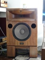
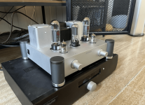
About two months ago, I got my hands on what has become my first tube amplifier.
It is a BRZHIFI A20. Ik got it fairly cheap second hand and simply wanted to get a taste of wat tubes could give me. At that time I was not aware of the rabbit hole I would get myself into haha. I also had no real experience with how amplifiers work. It truned out to be a rather fun journey and I learned how tube amps work along the way. It took me around two months from getting the amp to finishing the last mod.

Once I got the BRZHIFI A20, I was "amazed" at how it sounded for the given price point. Bear in mind I had ZERO expectations of the product. Still I missed something to the audio. My reference is a Thule IA60 amp, combined with Piega P4L speakers. Compared to the Thule, dynamics, low- and high-end extension were missing quite a lot. Also the voice sounded a bit metallic at times. Yet wat was clear to me is the "opennes" of the voices the BRZHFI A20 managed to render surpassed that of the Thule.

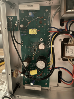
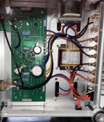
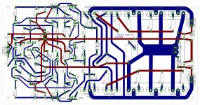
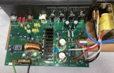
While looking up video's on cheap Chinese tube amps, I noticed the Reisong / Boyuurange A10 and A12 looking VERY similair to the BRZHIFI A20. When taking a look at the PCB's I noticed they were almost identical to each other, indicating they would use the same basic design for their products as most Chinese manufacturers do. Same thing happens in the Chinese watch industry, where majority of watches are based on the same movement.

While working on the BRZHIFI A20, I have learned the Reisong A10 was initially designed for 6v6 tubes. Link to forum
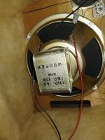
The EL34 Cathode resistors were already lowered to 330 Ohm/3w to accomodate a better dissipation in the BRZHIFI A20.
I also stumbled upon Skunkie's mods for the A10. Since the BRZHIFI A20 is practically identical to the Reisong, I decided to include all the mods in the end.

Starting out, the EL34's are running at about 60% plate dissipation which is very cold for what the tube is capable of.


Modifications I have done in the chronological order:

1)
Replace coupling caps
I have replaced the stock 220nf with Auricap XO 220nf versions.
The sound cleared up dramatically and the frequency response and sustain below 100Hz got resolved better, as also the higher frequencies became better audible. It sounds super smooth, but something also went missing!
It became clear the amp had some more flaws to adress.
While the dynamics had been restored partially, the amp now sounded lifeless. As if the soul was drained by some dementors. Also I noticed a lot of unpleasant distortion going on in the upper ranges (above 10khz). It also became clear the engineer at BRZHIFI matched all the parts in such a way to get the most out of the amp voice wise without stressing the components. The stock coupling caps provided the "soul" to the voices which was now gone. Also the stock caps were more rolled of the in the lower and higher frequency band, masking flaws and high distortion in the amp.

It is this single mod that opened the rabbit hole of improving this amp 😉

2) Bypassing EL34 cathode resistor
I read that bypassing the cathode resistor increases gain and can deliver better sound. I installed some 2000uf Cambridge Audio (probably rebranded Nichicon) caps. Immediately the soundstage came more to life due to 2nd harmonic distortion. It was about a 15% improvement.

3) Experimenting with different cathode resistor values on the chinese 6n2 's
I read that the Reisong A10 is using a probably too high value in it's pre-amp stage running the 6n2's quite cold. The Reisong A10 uses 2k resistors, the BRZHIFI uses 4k resistors which are bypassed.
I experimented with different values: 840 Ohm, 1k and 2k.
Based on this article I installed the 840 Ohm resistor. While I noticed an improvement in the 2nd harmonic, it became VERY clear the 6n2's are the limiting factor in further upgrading the sound. While the 2nd harmonic had increase, also have all the other distortions resulting in an even more muddy sound and more distortion in the higher end of the spectrum.
I reverted back to the original value of 4k.

3) Replacing the Chinese 6n2 with Voskhod 6n2-ev
While working on this amp, I ordered some NOS Voskhod 6n2-ev 's. I read that they should improve the soundstage and give better treble. Both things that the stock ones are missing.
When I finally received them, I noticed the immense difference in the build quality. The Voskhod is built way better overal. This looks promising!
In installed them, using the stock 4k cathode resistor. Wow! What a difference that made! Not only did the holographic image improve, also did indeed the higher end of the frequency spectrum have less distortion albeit it subtle. It is clear there are more limiting factors elsewhere in the amp.

4) Replacing the diodes with Ultra Fast ones
No audible difference

5) Lowering cathode resistor value on the Voskhod 6n2-ev
Now with better tubes installed, I decided to lower the cathode resistor values once again.
I decided to go for 1k as skunkie uses this in her A10 / A12 modification.
And wow did this improve the sound enormously! The voices are really singing like they are in my room.
The holographic image improved a little also. And best of all: No added unpleasant distortion. The sound is very clear.

6) Lowering cathode resistor on EL34 from 330 Ohm to 250 Ohm
I learned that lowering the cathode resistor does increase the bias. Therefore I tried to lower the values more on the amp.
This gave a noticeable improvement, but not still quite there yet. But I started to see where this was going to.
I noticed lower distortion and better low- and high-end extension. Also the dynamics improved a bit and distortion became less.

7) Replacing Voshkhod 5Z4P with Sovtek 5AR4 rectifier
While going lower on the cathode resistor, the moment would come that the stock recitifer tube would not be able to keep up with the increased demand of current.
I decided to go for the 5AR4 rectifier as this one had a slow startup, could handle the increase in powerd demand and had lower sag.
Difference in sound was more power overall. It sounded less mushy, but not by a great margin.

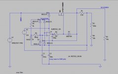
8) Shade (shunt / plate-to-plate) feedback resistor 840k
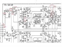
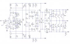
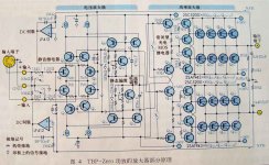
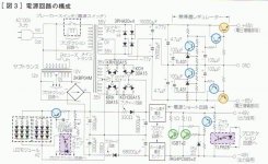
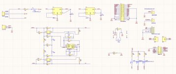
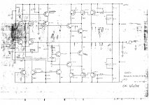
I first read on plate-to-plate feedback in a forum posst by Skunkie while working on the Reisong A10. I was already aware of the schematics her design for the Reisong A10.
I decided to experiment with the local feedback and give up on the zero feedback approach.

By far I can say this has made the biggest improvement in my opinion. The distortion got substantially lower and the sound cleared up dramatically. Metal and hardrock was now beginning to become bearable.

9) Complete skunkie overhaul as describerd in her Reisong A10 mod guide.
After installing the Shade feedback and finally understanding the design of the amp, I decided to go all the way and do all the Skunkie mods to the BRZHIFI A20.
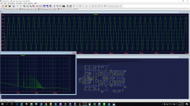
I also learned how to measure the voltages in the amp. So I had enough confidence to make it a succes.

And wow did it lower the distortion even more! I could complete all the mods except for the cathode resistors on the EL34. I measured different plate-to-cathode voltages and lower voltages on the resistor thank Skunkie does. According to my calculations I would get around 70% dissipation with the current 250Ohm resistor in place. So I knew the final touch would be getting the dissipation to around 90% which should not be an issue with Class A amplification.

10) Replacing bypass caps by different values
Nothing much, simply replacing the installed 6n2 cathode bypass and replacing the old Cambridge bypass caps on the EL34 cathode bypass.
I cannot say I noticed an improvement over the old capacitors I had installed, they were prety decent already.

11) Final lowering of the EL34 cathode resistor to 150 Ohm
Moving from the higher 330 Ohm resistor to a 250 Ohm one, I noticed a voltage drop accros the cathode resistor which I did not anticipate. The 250 Ohm resistor with the measured voltages at 330 Ohm should give me between 80% and 90% dissipation. With the new values this was around 70%, which still was an inprovement.

Based on the amount of voltage drop, I would have multiple scenario's. The lowest I would dare to go was a 150 Ohm resistor.
I ordered a 180 Ohm and 150 Ohm resistor and some 10 Ohm resistors to add in series to get a gigher resitance if needed.
I first attached the 180 Ohm resistor and measured 85% dissipation, not quite where I wanted it to be.
I settled on a 150 Ohm resistor in my case. This gives me a 92% dissipation which leaves me in the safe range when accounting for tolerances.

The final lowering of the resistor (together with the Schade feedback) is what I would say made the biggest impact in the system overall.
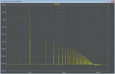
The dynamics are now restored and I could even lower the volume. Distortion seems almost gone (cannot measure it unfortunately).
The sound is very clear and open. I am amazed at what a staggering difference the mods make.

12) Install Gold Lion KT77
The last thing I wanted to try is to place some "respected" tubes in the amp as a replacement to the Psvane El34c that come with the amp.
The effect is there, but subtle.
Low- and high-end extension is better on the Gold Lion KT77, however the EL34 renders voices a tad bit better. This is a matter of preference and fine tuning.

Overall impressions in retrospect:
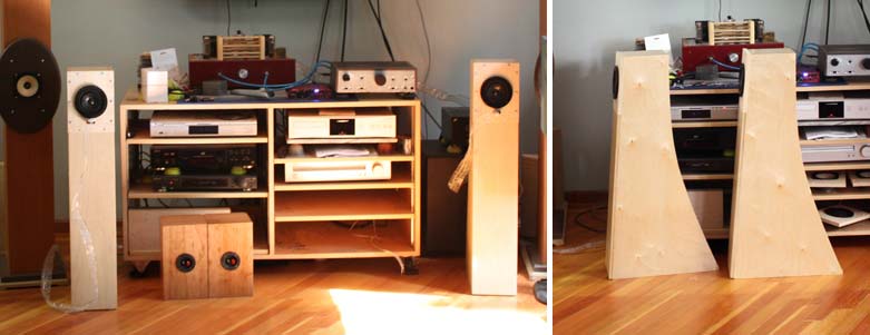
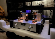
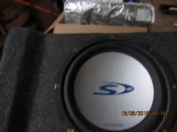
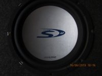
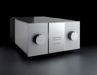
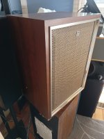
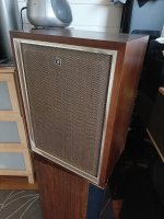
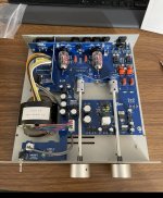
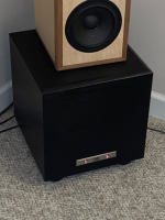
I'd say this is a nice amp to learn the basics of tube amp design. It was at least for me. As you can see in the pictures I also own a Thule Spirit IA60. Great solid-state amp which I use as a reference. With the mods done I am very impressed of that the BRZHIFI A20 can deliver. When I first got the amp, I could not decide which one to keep. I decided to keep the BRZHFI A20 to see if it would grow on me. But something still was missing.

After doing the mods I might sell the Thule. I have not reverted back since doing the mods. The Thulse of course still wins in terms of sheer power, dynamics and distortion figures, but the BRZHIFI A20 with the mods sound better in the other cases now.

What I also noticed is the perceived volume level changed completely with the mods.
My neighbours started complaing about hearing my music when I first got the amp, and I did not understand why. To me the perceived volume was the same as on the Thule IA60 amp. I decided to measure my dB and got to the shocking conlusion I had to crank up the BRZHIFI more than the Thule at around 8dB to get to the same perceived volume.
After doing the mods I can lower the volume again! I usually settle around the same volume or a little bit ( 1dB) higher than the Thule since doing the mods. No more complaints from the nieghbours. How crazy is that!

I want to give Skunkie a big digital hug for sharing the mods with us. It made the amp go from hot garbage to a very pleasant listening experience.
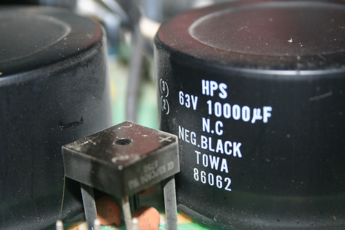
Attachments

  • 2022-12-06 12_19_31-Persoonlijke Album.png
    2022-12-06 12_19_31-Persoonlijke Album.png
    900.5 KB · Views: 402
  • 2022-12-06 12_18_31-Persoonlijke Album.png
    2022-12-06 12_18_31-Persoonlijke Album.png
    533.1 KB · Views: 347
  • 2022-12-06 12_20_49-Persoonlijke Album.png
    2022-12-06 12_20_49-Persoonlijke Album.png
    389.5 KB · Views: 369
  • 2022-12-06 12_19_13-Persoonlijke Album.png
    2022-12-06 12_19_13-Persoonlijke Album.png
    562 KB · Views: 350
  • Like
Reactions: AudioFanMan

Cheapskate dumpster diving speaker

OK not quite dumpster diving
Landlord across the road was cleaning out the house across the road and just now put this on the verge. I haven't pulled the driver out of the box but it seems to be in reasonable but dirty condition and is not open circuit by a battery test
Not yet sure what the exact model is yet
Shocking shonky box
Worth playing with or straight to the recycle bin or trading post?
I don't have a sub with my computer speakers yet
Anybody give me the model or data from a quick eyeball?

Attachments

  • IMG_0977.JPG
    IMG_0977.JPG
    95.3 KB · Views: 465
  • IMG_0978.JPG
    IMG_0978.JPG
    86 KB · Views: 470

Eico HF-81 C23 C24 Value change

Hello all, It's my first post here!

C23 and C24 in the Eico HF-81 in question here. Schematic found here: https://www.thetubestore.com/lib/thetubestore/schematics/Eico/Eico-HF-81-Owner-Manual-Schematic.pdf

It looks like these are local negative feedback coupling caps (150pf). One of these is physically damaged and I would like to replace them. The issue is that I don't have the proper value and voltage rating on hand but I do have 430 pf 630v polystyrene caps on hand so I'm wondering how this will impact the performance of this stage. I'm getting different results from online calculators for this circuit. One is showing me it's essentially flat with the 150 pf cap and the other shows that the -3 dB is around 120 Hz. I'm assuming a load impedance of 5M for the grid of the 12ax7 (V5b, V6b). If the circuit is already fairly flat, then I'd assume raising the cap value shouldn't effect the response in a way to be sonically noticeable or detrimental in any way.

Thanks for any help!

JENSEN LS-2b Two Way Bookshelf Speakers, no crossovers?

Hi All.
A very nice gentleman dropped off a pair of Jensen LS-2b Loudspeakers for free today.
The first thing I noticed was the foam surrounds were toast and need replacing.
I then removed the driver to find the complete absence of a crossover or any parts (capacitors, inductors, nor resistors).
The cabinets are in walnut vinyl wrap.
The one of the main drivers is stamped JI050 31285 NUMBER 2207938
The one of the tweeter drivers is stamped C9972 31114 NUMBER 2207938
The thin internal cabling is soldered directly to rear of the cable terminal plate.

Were there cheaper versions of this speaker model progressively over time?
Is there a factory specified crossover (values etc) .
I'm happy to build crossovers to improve these speakers.
thanks cliff

FullRange 2 way Tang Band 1808 and LB12 suggestion

I have a Pair of TB 1808 8" FR drivers and a pair 12" Eminence Lab12 driver Looking for suggestion to make system thats 2.2 so FR will be seperate box and subs will be seperate box Also I have a Pair of peerless STW 350 15" sub drivers so incase you feel lab cannot do and STW can I have no issue

have Hypex amps and miniDSP 2x4HD no skils to calculate box or make passive crossover.
Room Size is 15ft wide 28ft depth and 10ft height
I listen to various music like techno electronic and pop also I like loud.
regards
anand

TBP-Zero Class A: Research and build

Hi folks,

Not sure if this is the first BUILD thread, but I am sure there's very limited discussion about this power amp.

TBP-zero is a class A amp design without emitter resistors, fully-balanced architecture, and looks very complex to build. I've never build class A without emitter resistors, this is a new challenge.

Thanks to my friends, D.L. and Luke Chu, they help with simplifying the design, making it easier to build and more DIY-friendly. The fully-balanced symmetrical design is modified into single-ended, that means half of materials and cost!

The project will be open-sourced, and Eagle sch and .brd files would be published later for further discussion.

Please be noted that some details on the magazines will conflicted.

Any suggestions are welcomed. 😉

Attachments

  • TBP-Zero-clone-S_DC-srv_LIM.asc
    TBP-Zero-clone-S_DC-srv_LIM.asc
    22.1 KB · Views: 232
  • Single.jpg
    Single.jpg
    96.3 KB · Views: 1,408
  • post-69184-0-34216000-1372316455.jpg
    post-69184-0-34216000-1372316455.jpg
    98.1 KB · Views: 1,371
  • FFT.jpg
    FFT.jpg
    74.2 KB · Views: 1,157
  • 22154273_1972378102778403_7300731344173834352_n.jpg
    22154273_1972378102778403_7300731344173834352_n.jpg
    70.7 KB · Views: 1,149
  • LT1.png
    LT1.png
    221.3 KB · Views: 1,280
  • tb_zero_int_01.jpg
    tb_zero_int_01.jpg
    23.8 KB · Views: 631
  • BRD1.jpg
    BRD1.jpg
    1.1 MB · Views: 738
  • 22135729_1972375122778701_1497850650095998450_o.jpg
    22135729_1972375122778701_1497850650095998450_o.jpg
    79.9 KB · Views: 851

Amplifier with Buzz & sensitivity at Line-IN - What to do?

I have an issue with an active speaker: a B&O BeoLab 8000 with built-in amp.

It has an RCA plug for line-in that I want to use. And it has an Auto stand-by function which means: the amp & speaker switch On when audio signal is coming in, and it (normally) switches Off/stand-by within 3 minutes after the audio signal has ended. I have a kind of distortion that causes buzzing noise. The noise is too loud for the amp to switch to Off permanently. It does try to switch Off, but it then immediately switches back On again, and then tries to switch Off gain. This process repeats continuously.

This happens both when I have nothing connected to the RCA connector for Line-in, as well as when I have an audio source connected to the Line-in. Though the buzz is a little bit less when I plug an iPhone as an audio source to the RCA line-in connector. But even with a source connected to the RCA, there still is a lot of sensitivity. Because when I touch the cable that connects the RCA connector to the AMP, it immediately switches On again.

PCB with RCA Line-in connector: Left = bottom side, right = top side:

PCB05 - Top view Close-up.jpg
PCB05 - Dismantled.jpg


Next I put a 10K resistor across signal input & ground input. Without an audio source connected, it even increased the buzzing noise. With an audio source connected, the resistor makes no difference.

So I am confused, what is going on?
Anyone with help/suggestions/instructions?

Freshen up pair of AKAI SW-130 Loudspeakers

Hi All.
I acquired a pair of AKAI SW-130 Loudspeakers the other week.
They feature Japanese 12" Woofers, 3 1/2" Tweeters, iron core Inductors, & 4μF omats branded electrolytic capacitors.
These speakers have a reasonable sound.
I haven't removed to test the caps, but they are more than 50 years old.
Polypropylene would be nice, but is there a recommended electrolytic capacitor which could do the job at an economical price?
Also the fabric covering the baffles is marked and appearing a little tired.
Is there a fabric cleaner which is recommended?

Attachments

  • Akai Speakers 1.jpg
    Akai Speakers 1.jpg
    406 KB · Views: 1,122
  • Akai Speakers 2.jpg
    Akai Speakers 2.jpg
    417.1 KB · Views: 772
  • Akai Speakers 3.jpg
    Akai Speakers 3.jpg
    353.5 KB · Views: 533
  • Akai Speakers 4.jpg
    Akai Speakers 4.jpg
    444.8 KB · Views: 621
  • Akai Speakers 6.jpg
    Akai Speakers 6.jpg
    391.7 KB · Views: 568
  • Akai Speakers 10.jpg
    Akai Speakers 10.jpg
    408.6 KB · Views: 479
  • Akai Speakers 11.jpg
    Akai Speakers 11.jpg
    519.8 KB · Views: 742

Amount of hornloading in a Synergy horn

As the title suggests: how much hornloading can we expect a synergy to have for the sub 500hz frequencies? I guess it depends on the horn used?

I will be using a large biradial horn, with a 108x75cm (42,5"x29,5") mouth. I will be converting it into a 2-way with a 500hz crossover point, so off axis ports at 17cm (6,7"). I was planning on using 2x 15" drivers.

Question is:
- is there a ballpark estimation / rule of thumb to knowing how much hornloading this wooferpair will be able to get. Lets say over a 80-500hz range.
- Or should I model this? I'm not at home in all this software (like hornresp) so I dont really know how to do this.
- also, would this be a good range to use 18" drivers for? Or is this counterproductive?

Preamp recommended for Elekit TU-8800 SET Amp? Suggestions for my audio setup?

Did anyone try any preamp to pair with ELEKIT TU-8800? What's outcome? Worth the efforts or money? How about tube buffer (another rabbit hole or snake oil? LOL)?

My setup:
Digital source: Raspberry Pi 4B (running Volumio + Qobuz HiRes streaming & FLAC/DSD local files on a USB hard drive) + iancanada FIFO reclocker & HDMI I2S output
DAC: Denafrips PONTUS II using HDMI I2S input
Amp: Elekit TU 8800 SET tube amp with KT-88, transformer/resistor/pod upgrade, (still debating about the capacitor upgrade)
Speakers: DIY version of Decware ZF15L with Lii Audio F-15 drivers (https://www.decwareproducts.com/zms), plus a solid-state sub-woofer plate amp to drive a Lii Audio W-15 woofer driver to compensate for bass frequencies below 60Hz
Room size: Width 12 ft, Length 20 ft, Height 7ft
Room treatment: some DIY diffuser and absorber panels on 4 walls, floor is concrete with carpet, drop ceiling
Listening position: 4~5 ft from backwall
Speaker position: 4 ft from front wall, 1 ft from side walls

Listening Impression: with good recordings, I can hear wall of music coming towards me with instrument separations and some depth behind the speakers. The soundstage does not extend beyond the left or right of the speakers (except for 1 or 2 live concert songs). The vocal is at eye level (driver level), kind of low for me. Just wondering if there is any room for improvement and how.

Thanks for sharing your experience or thoughts in advance.

DIY project: acoustic upgrades to an existing speaker (horns & cabinet design)

Hello everybody: here I am to propose my first diy audio project. I am very intrigued in the acoustic amplification of sound and want to check out for myself if I can make an upgrade to a system I already have. Some background information: I am an engineer-architecture student with good carpentry skills (furniture-making), a very basic knowledge about electronics and a low budget 🙂. I am equally concerned about the looks of the project as I am concerned about its performance (that's just how architects are... 🙂 ).
As I am on a low budget, I want to work with the things I already have in my posession
-Amplifier: American Audio VLP1500 2x500W RMS into 8 Ohm
-Equalizer: Behringer
-Speakers: JBL JRX125 passive speakers (2.5-way system; Frequency Range (-10 dB):2 35 Hz - 16 kHz; Frequency Response (±3 dB):2 45 Hz - 12 kHz)

So what I plan to do is upgrading this setup by only working on the cabinets (I will keep and use all drivers and the crossover), and I would want to do this by introducing acoustic horns into the cabinets. The JRX125 design is super basic, it is just the compression driver and woofers mounted in a hollow cabinet that fits al three.
Here are some things that I think you should know:
-size doesn't matter (I will make multiplex cabinets from scratch and they can be as big as they need to be)
-I have an equalizer so the system itself doesn't need to be tuned perfectly
-I want the system to be LOUD, not especially good sounding; the components I have available are not high quality so I don't expect them to be super loud or good sounding but I want to see how far I can take it with the cabinet design

The speakers are a 2-way, almost 3-way design; in the images I included a scheme of the crossover which is basically a HP filter @ 2kHz for the compression driver, a LP filter @ 2kHz for the first woofer and a LP filter @ about 350Hz for the second woofer (JBL doesn't give exact values in their spec sheet so I tested this just by hearing).
-the compression driver is a JBL 2412, 1" exit compression driver (mounted on a JBL Progressive Transition™ Waveguide)
-the woofers are both JBL M115-8A 15" woofers

So I think I would design this setup as a three-way system with
-one 15" JBL M115-8A woofer LP filtered at 350 for the bass cabinet
-one 15" JBL M115-8A woofer LP filtered at 2 kHz as a midbass cabinet
-the 1" JBL 2412 compression driver for the high notes
In the image in the attachment I suggest how this could look like (note: this is just a quick sketch I made on top of a cubo15 sketchup file, nothing serious), I have been inspired by DIY soundsystems for dub and reggae music as they also have to be cheap and loud with a lot of bass.

Now come my specific questions:
-BASS: can I just download a cabinet design for a 15" folded horn bass cabinet and use this for my M115 driver? https://freespeakerplans.com/plans offers these free building plans with some suggested drivers, I dont find any specifically made for my cheap driver so I would have to use a plan not specifically made for mine. If not, which values of my driver should I compare to the driver used in the example project? Could I lower the frequency output of my speakers by using a more efficient cabinet design than the standard 'dumb box'?
-MIDBASS: as the frequency of the second driver goes from about 40Hz up to 2kHz I was looking to make a frontloaded horn with bass-reflex, similar to that one of the ALTEC 816. Is this a good idea? By the way how comes that these front loaded horns partially cover the driver (see in picture)?
-HIGH: the JBL 2412 compression driver comes with a standard JBL Progressive Transition™ Waveguide, can I make an upgrade for this? Is there a DIY way or another waveguide that I could buy that would make the electricity-to-sound efficiency even higher than it is with the standard? A bigger waveguide, or an exponential horn? Maybe a multicell horn?

I hope my intentions are clear, any replies would be of great help!

Attachments

  • Schermafbeelding 2022-12-03 om 19.04.39.png
    Schermafbeelding 2022-12-03 om 19.04.39.png
    24.2 KB · Views: 207
  • 816A_1.jpg
    816A_1.jpg
    232 KB · Views: 196
  • JBL_JRX125.v1.pdf
    JBL_JRX125.v1.pdf
    174.2 KB · Views: 172
  • preview.jpg
    preview.jpg
    54.4 KB · Views: 172

How to control Peak LED sensitivity in this circuit?

Hello,
I got a fully working VU meter module from Tascam 112 tape deck.

Analog meters sensitivity can be controlled indenpendently by potentiometers R103/R203 and this settings does not affect the peak leds.
My question is how to change the peak leds sensitivity? For now they lights up when signal on input is about 0.480V. I want to be able to adjust it so they will light up on any other level, for example +3dB (1.094V).
My first shot was to manipulate with R107 and making it a bigger value. This negatively affects whole circuit sensitivity, which is not acceptable 🙁
Is there an easy way to do that? I assume the resistors R108 and R109 determines the input voltage for Q101 transistor (2SC6203F).

Here's the complete schematic diagram of the circuit.
Any help is appreciated 🙂
4593615600_1669985934.jpg

HP339A distortion analyser

I have managed to make a total donkey of myself and damage a HP339A distortion analyser that I have no documentation for. I inadvertently plugged it into 220V instead of 110V. Naturally the external fuse didn't blow before it damaged internal components. I live in Saudi Arabia so don't have a good repair shop here. The damaged components are diode bridges D301 and D302 and diodes D303 and D304. If someone has a parts list and ideally schematic I can access via PDF or via other internet means (or knows where I can find such information on line) I would be most grateful as I could then source bits for a repair. The parts don't have identifiable markings on them.
The instrument's owner will be coming back in 4 days and I'll be one dead donkey if it's not working.
Hoping someone can help ...EEE AWWW!:dunno:

Headphones

Hello to everyone!

I have just built up a very simple headphone amp with two NE5532. It works very well and I just would like to know ,

if I've made some cardinal faults in the schem, for example if I did some "Don'ts" or forgot some "Do's".

Please have a look at the attached schem and tell me what You think about it.

A little problem I have is the popping sound in the headphone when I turn on or off the power supply - especially when the positive and negative supply voltages don't raise or fall exactly at the same time.

Does anyone know a good way to avoid this?

Any hints would be appreciated!

Attachments

  • 418864E5-1EC0-4395-98B1-1DF62BD2844B.png
    418864E5-1EC0-4395-98B1-1DF62BD2844B.png
    3.1 KB · Views: 243

NAD 216 red protection problem

I'am using two NAD216 in bridge mode with soft clipping off, and one night one of my amps just turned off without any reason, just hade the tv on so there was no loud volume involved.


When i try to start the amp it never switches from red to green as it suppose to and the red protection lamp constantly lights.


I've scooped the internet for every clue but no really luck, iam no electrical engineer so what to measure and how isnt my strong side but soldering is more like me. So ive read up on the web and swapped a few parts but no luck so far.


Things i have changed are as follow...


R243, R244
R203, R204
R201, R202
R236, R238, R239
C218, C219
and the output realy RL 201

Attachments

  • leftchannel.PNG
    leftchannel.PNG
    340.7 KB · Views: 675
  • rightchannel.PNG
    rightchannel.PNG
    319.6 KB · Views: 671
  • powersupply.PNG
    powersupply.PNG
    310.9 KB · Views: 633
  • mains.PNG
    mains.PNG
    72.7 KB · Views: 659

For Sale Miscellaneous tubes, parts, bunch of sleeving

I have a bunch of stuff I don't need, including tubes, parts, and a bunch of spools of expandable sleeving of various sizes and types. They're currently listed on eBay, but I would be happy to entertain any offers. Pics can bee seen on eBay or I can send them if you want.

Matched pair NOS Mullard GZ37 CV378 rectifier tube WB (P3)

Full 500' spool - 1/2" PET expandable sleeving, white - Techflex FRN0.5TW

Partial 250' (~200’ remaining) spool - 1/2" nylon expandable sleeving, copper- Techflex NMN0.5CP

Partial 500' (~200’ remaining) spool - 3/8" nylon expandable sleeving, black- Techflex CCP0.38BK

Partial spool - ~50' 3/4" PET expandable sleeving, carbon - Techflex PTN0.75CB

Full 250' spool - 1/2" nylon expandable sleeving, silver- Techflex NMN0.50SV

Partial 500' spool (~250’ remaining) - 3/8" PET expandable sleeving, carbon - Techflex PTN0.38CB

Partial 250' spool (~200’ remaining) - 1/2" nylon expandable sleeving, silver- Techflex NMN0.50SV

Partial spool - ~100' 3/8" nylon expandable sleeving, blue - Techflex PTN0.38BL

Enormous 120V:120V toroidal isolation transformers, 2500VA and 5000VA, 50 pounds or more!

JBL PB10 Help - Transformer getting hot

The HT sub started to act crazy, it would work ok for a couple of hours, but then the bass would eventually disappear.
I pulled the amp out and noticed a pair of caps were swollen, replaced them easily with the same value and it started working again.
That was encouraging but soon noticed the transformer was getting hot, very hot and this plate amp wasn't even back in the enclosure; which is a sealed plastic box inside the speaker box. I left it out on purpose just in case of something like this.
Not a lot of components on the plate amp, and they all look in good shape.

Since the plate amp is not in the box, I didn't reconnect the LEDs - Con3a1

Would hate throwing it away, any hope with this?

Thanks for looking!

Attachments

  • PB10.jpg
    PB10.jpg
    500.9 KB · Views: 426
  • JBL.png
    JBL.png
    1.4 MB · Views: 238

Capacitor hardware sources

I‘ll appreciate help with finding clamps (at a good price) and “capacitor terminal screws“ at the Mouse where I usually get my parts.

1. Clamps for 13/8 multi-section capacitors (50+50 uF). I found these for a lot of money. https://www.mouser.com/ProductDetail/Cornell-Dubilier-CDE/125565-06?qs=0uhOF6wYX64NvonUFAHLJg==
Is it really priced at $8.10 for one clamp? Am I looking at the wrong type. Why are these so expensive?

2. I bought these caps at Mouser with screw terminal like that arrived without screws. I can’t seem to find them in the Mouser website. https://www.mouser.com/ProductDetail/80-ALS70A681DE500

Threshold CAS-1 Capacitors

See the attached schematics

I want to replace the tantalums as the Mr. Pass has suggested in some other topics discussing Threshold products.
In particular this amplifier has 2x 47uf/20v tantalum caps at the power stage, 1x 47uf/20v tantalum coupling cap at the line stage and not-sure-what-that-part-does stage 220uf/10v.

My plan is to use some well known caps such as elna silmic 2 but I am wondering if I can swap the input coupling cap for a better one - polypropylene film cap. 47uf film caps are really expensive, I wonder if I can replace it with lower nominal caps... For instance it does not have to be rated for such high voltage - 20v. If I am going to solder in a bipolar cap. I could do with 5v max - as far as I know the amp input sensitivity is bellow 2 volts.

What about its capacitance? My almost-non-existant electronics knowledge tells me that a cap and the input impedance form a high pass filter. I am not entirely sure what's the input impedance, but on some booklet I've seen it stating 75k. Hell, I believe we can agree that 10k would be the absolute minimum. With a 10k input impedance and 10 times lower capacitance 4.7uf cap I will have an f3 of ~4hz. And in case the impedance is actually 75k, f3 is even lower.

I am wondering if all this my rambling make any sense about swapping the input capacitor for a lower value polypropylene capacitor instead of maintaining the same nominal 47uf electrolytic.
Do you think it is safe to conduct this experiment in practice?
Thanks!

Attachments

  • CAS1.jpg
    CAS1.jpg
    372.1 KB · Views: 132

For Sale Richard Marsh Headphone amp Kit + power supply

==Sold==

Richard Marsh Headphone amp Kit by TechDIY. Board and complete kit of parts including matched parts as recommended by Mr Marsh. This is a kit to build the amp boards themselves.
Build/Info Thread
I will also provide the copy of Linear Audio article that I purchased.

Also, 4.17UV ultralow noise power supply regulator +-12/15V 1A from diyinhk.
Link to shop

Any reasonable offer accepted.

For Sale Tang Band W8-2145

Selling 1x pair of Tang Band W8-2145

Fullrange, 8" drivers

They have about 40hrs on them and are like new in the original packaging
Used to test an open baffle setup (which was great btw!). For people closeby the baffles are available free of charge (18mm baltic birch). Located in Eindhout, Belgium

SOLD

Will ship worldwide

Attachments

  • IMG_3119.jpeg
    IMG_3119.jpeg
    504 KB · Views: 196
  • IMG_3120.jpeg
    IMG_3120.jpeg
    395.3 KB · Views: 151
  • IMG_3121.jpeg
    IMG_3121.jpeg
    398.3 KB · Views: 149
  • IMG_3122.jpeg
    IMG_3122.jpeg
    321 KB · Views: 197

For Sale Sunvalley SV-EQ1616D for sale

Sunvalley adjustable equalization phono stage for sale; low hours. I bought this as a kit and assembled it but have decided to go another direction. A set of tubes will be included, not including a rectifier tube, but the pictured diode bridge will be included. Requires 120V wall voltage. I built this per spec except that I included some extra shielding around the head amp; this is easily removeable. This unit has the optional Vcap upgrade. Tube guards, which aren't in some of the pictures, will be included (I don't use them). Asking $1100; free shipping to the continental US, at cost elsewhere. This phono stage has fabulous reviews! Look them up!
DSC03677.JPG

DSC03676.JPG

DSC03663.JPG

DSC03672.JPG

DSC03673.JPG

DSC03674.JPG

IMG_20220901_204753.jpg

QUAD 303 bias diode question / mystery ??

Hi all.

Hope somebody can help.
I have a Quad 303 which was faulty but i've fixed the fault ( open cct resistor on one of the driver boards ) and I intend to make 2 new amplifier boards and PSU board from scratch with HQ components throughout. Im puzzled by the schematic for the 303 and the actual board ? - The schematic shows 4 diodes around transistors tr103 and 104, but the actual amplifier has only 2 diodes ? I havent as yet verified why there are only 2 diodes fitted , but I will trace the tracks - any ideas what s going on with just the 2 diodes. Thanks . attached is a portion of the schematic im talking about

Attachments

  • quad 303.jpg
    quad 303.jpg
    19.7 KB · Views: 141

MarkAudio CHP-90 mica + DDVP-12.5-ML [TQWT]

I installed CHP90 in a small TQWT.
CHP90 is high quality and powerful in all band.

Login to view embedded media

Attachments

  • CHP90-01.jpg
    CHP90-01.jpg
    90.4 KB · Views: 474
  • CHP90-02.jpg
    CHP90-02.jpg
    99.3 KB · Views: 602
  • CHP-90mica-01.jpg
    CHP-90mica-01.jpg
    111.9 KB · Views: 850
  • DDVP-12.5-ML-01.jpg
    DDVP-12.5-ML-01.jpg
    153 KB · Views: 937
  • DDVP-12.5-ML-02.jpg
    DDVP-12.5-ML-02.jpg
    95.3 KB · Views: 746
  • DDVP-12.5-ML-03.jpg
    DDVP-12.5-ML-03.jpg
    112.8 KB · Views: 552
  • easy-ladder-cable-05.jpg
    easy-ladder-cable-05.jpg
    138.8 KB · Views: 478
Projects by fanatics, for fanatics
Get answers and advice for everyone wanting to learn the art of audio.
Join the Community
507,506
Members
7,875,064
Messages

Filter

Forum Statistics

Threads
405,623
Messages
7,875,064
Members
507,506
Latest member
Marcinpditty