Scratchy pots and hum - Roland Cube 60 bass

Hi,

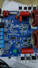
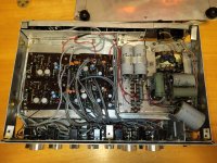
I have Roland Cube 60 bass (orange, older version) on my bench.
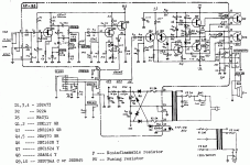
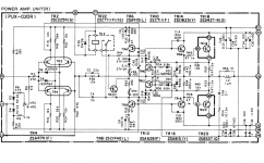
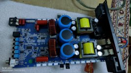
Power amp is good, no noise, healthy.
Power supply caps are replaced with new, all voltages are correct.

Problems are located in preamp, scratchy pots and hum of around 150Hz.
Hum dissapear if I switch preamp off and use power amp only.
Hum is not Volume pot related, it is there after amp is ON.

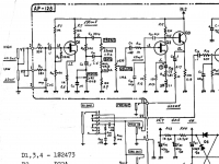
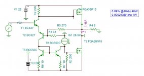
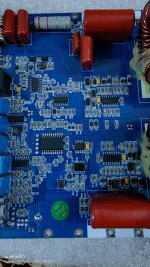
Preamp is built around three transistors (Q1,2,3).
-voltages in preamp on Q1 (2SK117) are OK
-all 4 pots in tonestack are replaced- new -no change, no DC anywhere.
(Vol pot is especially scratchy then treble and Mid + Bass less)
-all tonestack capacitors and resistors arround Q2,Q3 are new
(Q2 is 2SK117, Q3 is 2SC2240)
-voltages on Q2+Q3 are not OK, according to schematics
(Q2: G= close to 0, D= 28,2V, S= 0,33V; Q3: B= 28,2V, E=29,6V, C=37V)
-it seems there is also problem with L1 (measured 10H and 270ohm DCR)
-Q2+3 were tested outside PCB (no shorts or leakeage)
-grounding is tested and checked a few times, all OK

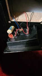
There isn’t any data about L1, it is marked on the body: 5R.
It looks L1 is part of series filter with R16 (1,8k) and C8 (1uF).
L1 is tied to ground with one end.
If I ground the other leg of L1, hum dissapear, sound is a bit changed.
If I ground it at the input, hum is completely gone.

Any ideas regarding scratchy pots, L1 and voltages on Q2+3?
I don’t have spare transistor Q2+3 to try, must be ordered.
What would be value of inductor at this location for bass amp?

Thanks in advance!

Attachments

  • rolandcube60bass.gif
    rolandcube60bass.gif
    95.1 KB · Views: 203
  • E48D20B3-FAC2-4197-AA52-FF2C0D572EFE.png
    E48D20B3-FAC2-4197-AA52-FF2C0D572EFE.png
    559.7 KB · Views: 141

Implications of cap value on input.

Im trying to understand the implications of the first cap on input to pre-amp.
Have purchased all the el-cheapo preamps being sold in my country.
Im comparing them to study differences.
Today is a bad day with brain fog. So apologies in advance if some of you consider this a stupid question.
The two caps in question are C1 and C2. If I remember right these are called input decoupling caps.
Their purpose is to remove any DC from the input signal right ?. As the input signal is off a MM turn table. I see no reason for any d/c being present on the line.
Long story short. All the other boards I have use a 1 UF cap for C1 and C2.
This particular board uses 10 Uf. In a lot of places where the other boards use 1Uf.
What are the implications of using a 10Uf cap vs a 1Uf cap on the input line ?. And can I / should I just by-pass it
Is there a s/w that can simulate the impact of changing this cap or a web page calculator where I can change this value and see the impact ?.

Attachments

  • vasp-preamp.jpg
    vasp-preamp.jpg
    62.2 KB · Views: 240

Wavetek Rockland 5380a Spectrum Analyzer

Wavetek Rockland 5830a FFT Spectrum Analyzer , .005hz to 100 Khz single channel , 0.01 hz to 50 Khz dual channel . Can do Nyquist plots , Internal Tracking generator source . Auto-Calibration feature , zero's inputs. 110 dB signal to noise ratio. Ideal for Audio work . Waterfall plots .This is an excellent analyzer . Extra chassis available for parts . Comes with both user and service manuals .
Price $550 Cdn OBO
Second complete chassis available , but needs service.
An externally hosted image should be here but it was not working when we last tested it.


Shipping from Calgary Alberta Canada Postal Code T3C2A1
Weight is around 30 lbs
Note; Second chassis is available ,needs a new crystal in sampling card , otherwise it's all there. Best offers on it only please !

Old non-working Velodyne Servo sub and new sub amp?

I found an old non-working Velodyne F Series Servo sub and and wonder if, after removing its internal amplifier, whether I can power the woofer in ints enclosure with an exterior sub amplifier that has both volume and crossover controls. This is the THIRD Velodyne sub that I've found and carried home to test. The speaker looks great - the speaker and amp only respond when the volume control is touched or turned - and then only for a second each time. I have yet to breach the cabinet to remove the amplifier... I assume I'll need to remove the speaker for access. AT now 71, this will be the last Velodyne I carry home!

For Sale Parts for a Neurochrome balanced preamp

For sale are parts for building a balanced Neurochrome preamp --
1x input buffer
1x preamp power supply
2x input selector boards
1x input selector board

The cost for new is $407+shipping for the Neurochrome parts alone,
I am asking $380 shipped including the BOM (which includes the relays, lorlin switch, IC's, terminals, LEDs etc).

Other parts I have for this project if interested:
  • New/unused DIY audio store Galaxy 1U w/Aluminum Covers / 230mm x 170mm. Store price $79, asking price: $55
  • Neutrik XLR connectors and Bulgin anti-vandal switch
  • 2x relay based volume control units, controllable by either rotary encoder or remote control - $100

Attachments

  • 2022-09-30 13.47.44.jpg
    2022-09-30 13.47.44.jpg
    431.8 KB · Views: 291

WTB: HA9P5002-5z or HA9P5002-9z - Op Amps

Any chance someone has (2) HA9P5002-5z or HA9P5002-9z Ops Amps (SOIC-8) they would sell? Trying to build the Norwood IPS for the M2x DiyA amplifier?
I have looked everywhere and actually ordered both from Win Source who said they had 10,000+ of each version. After getting confirmation of my order from Win Source I ordered all the other parts needed from Mouser - only to get an email 24 hours later advising that Win Source is sold out. Mouser and Digi-Key both say Mid to Late 2023 to get some stock. Here I am hoping that someone bought a couple extras over the past few years.

PM me and we can work out the details. Thanks.

DTQWT with Altec 515 not JA8008

Summoning planet10

While horn enclosure build of altec 515 is almost done to death and is huge,
I am thinking is it possible to compact the whole enclosure by using troels Dtqwt design.

So my idea is having the 288 compression drive ,mid woofer 515 , and a bass woofer (have not decide which yet)at the back. This combo should be relative compact than the traditionsl build but also compensate the lack of bass extension of 515 woofer.

however I don’t know how to estimate the relative size or whether this idea is correct

I believe the crossover section are the usual suspects, 500hz and 50hz.

I am not requesting a fish but just want to know the feasibility and is their a reduction in size.

Harman Kardon HK640 broken left channel

Hello,

Quite a while ago I asked my dad for his old HK640 that we used to have at home. I remembered it having some problems and was interested in fixing it up and using it. I have made some progress, but am currently somewhat stuck. I've been working on it off and on for quite a while, so I can't remember the whole timeline 100% anymore, but I will try to sum it up as accurately as possible. (service manual is quite easy to find, for instance here)

I remember the amplifier being in use until about 10 years ago. I do not know since when, but for a few years before it being replaced, there was an issue with either one of the left/right channels, or one of the two speaker groups. I think it just did not sound right but it might have not worked at all.
Fast forward to a year ago when I got it from my dad. When I got it I think the left channel did not work at all. I opened it up and noticed C419 looked broken. I also retouched some solder points that looked particularly crappy and cleaned the pcb up a bit. After this, the left channel worked again, although it was slightly more quiet than the right channel. Did not have much time to continue working on it then, but used it for about half a year without much issue. Sometimes the left channel would get very quiet, but this was usually fixed by wiggling the balance pot a bit. A few months ago I left town for about 2 months, and when I got back the amplifier would not work at all. After some investigating, I noticed that one of the output transistors, as well as R445 were broken. I replaced all of the output transistors, as well as R447 and R445. I also cleaned all of the pots. After this, the right channel is completely fine, but the left channel is still broken. I do some testing and find that R449 is broken, and I also accidentally break the idling current adjust trimpot (woops). Replace both of these, still no left channel. I find R407 to be broken and also check most other resistors, who all seem fine. So I replace R407, still no left channel.

Currently, the status is that the right channel is fine, but there is a few volts across the left channel speaker output, while there is no voltage across TP401 and TP403 (the measure points while adjusting the idling current). I am new to audio equipment and have only done a few small repairs of other electrical equipment. However, I can solder (although not the best) and know about components and how to use a DMM. I have checked all transistors with the continuity mode of my DMM for shorts, but have not pulled them out to test them properly. I have also checked most capacitors with the resistance mode while on the pcb but have not found anything obviously faulty so far. I am afraid I am going to have to pull out all of the transistors and possibly capacitors to test them, which with my soldering skills will be a very big task, so I was hoping there might be some other things I could still try beforehand which I might be missing.

Sorry for the long messy story, I wanted to give as much info as possible. Any help would be appreciated.

Mundorf Silver Gold 10uf pair

I sell a pair of Mundorf Supreme Silver Gold 10uf matched pair caps. I buy this some 2 years ago for my crossovers by Hifi Collective in Uk. Caps are in verry good condition only the legs were cut and are now 3-4 cm long. This are verry big caps 110mm X 50mm, but with verry god sound. Price would be 150eu plus shipping inside EU. I pay for new over 400eu with shipping.

Attachments

  • m86122853844_3.jpg
    m86122853844_3.jpg
    50.2 KB · Views: 151

DENON PMA 830 2SA815 Transistor Sub

Hi All,

I have a dead 2SA815 driver transistor in my Denon PMA 830 Power amp. I have some MJE172 and 182 that I'm hoping to use a sub or the 2SA815 and 2SA915. On paper they have good specs that exceed the original in many ways. Although they have a lower max Vce, they should be well within their limits in this circuit so I don't see a problem there. One area that is lacking in my knowledge is how different Vbeon and Vcesat specs will operate in this circuit. The MJE have about 20mV higher Vbeon and 5mV or so lower Vcesat readings on my Atlas DCA so I'm trying to determine if this will be an issue. The base voltages are pretty small in this circuit so I was concerned that a difference in those specs may make a difference.

Power amp schematic is attached

Attachments

  • PMA-830 Power Amp Schematic.png
    PMA-830 Power Amp Schematic.png
    58.4 KB · Views: 172

Pioneer SA 7800 négative voltage on base and Emitter of power output transistors

Hello.
Need help for reanimated one PIONEER SA 7800.
All 4 output transistors are dead.
I replaced all burn resistors,4 drivers q23....q26,and tested all parts on power amplifier board.Voltages +&-46v...ok+&-48v...ok
But now on output transistors I have negative voltage.
I know,Its NSA Amplifier and need very strict control,but I don't understand where is problem.

Q1. B -14.5v E. -12.9v
Q3. B. -18v. E. -13.3v
Q4. B. -9.4v E -3.7v
Q2. B. -4.3v. E. -3v
On 4 collector's +...-46v....ok

Thank you

Service manual
https://www.manualslib.com/manual/940262/Pioneer-Sa-7800.html

Help needed - broken coil of Koss pro-4aa

Hello friends, and i wish you and your significant others my best for Xmas.

Well, i received an original 1974 headphone, with the plus that it's non working.

I guessed someone else put their hands on it, since the coil threads are broken to the pins, and it seems I'm not able to find where the two threads start on the coil...
How can I solve this misters?

Yes i know about the lifetime guarantee etc., But i really don't know whether this works also here in Europe.

So, the question is, how do I take out two threads at the two ends of the coil?

I try to attach some pictures, hope to clarify how things are.

Thank you again and my best wishes!

Attachments

  • 16720007776728015705998379304460.jpg
    16720007776728015705998379304460.jpg
    104 KB · Views: 119
  • 16720008109668896528760998311944.jpg
    16720008109668896528760998311944.jpg
    54.5 KB · Views: 109
  • 16720008385818494327552142993860.jpg
    16720008385818494327552142993860.jpg
    70.2 KB · Views: 102

A small driver problem

I have a nice pair of Sansui floorstanding speakers here that I wish to convert from a 2-Way into a 3-Way.
The Sansui has dual 8" woofers in a tall box
I have a pair of the Hi-Vi TN28 given to me by rabbitz a while ago to top mount.
I intend to use the existing tweeter position in the top of the box to place a small midrange.
What I am looking for is a driver with an integrated can type assembly that will fit in the existing tweeter hole position,
I have a pair of Foster drivers here but they are 5.5" and too large.
Before I start mucking about with coffee cans and mounting from the rear does anybody know of an existing 100mm midrange with a can of about a litre or so that isn't your typical sealed back mid?
I don't know of any sealed back mid that sounds good crossed over as low as 400Hz, if you do I may be interested if you could post a link
  • Like
Reactions: ginetto61

Hi from Belgium!

Hi all!

I've been a member for a couple of years now, it occured to me i havent introduced myself yet 🙂

I dont have much electronical knowledge, but i do love thinkering alot and love to take stuff apart and improve it! Mostly i search this forum for diy solutions and upgrades.
i now own a cute little chinese tube amp, the audioromy FU29, which use the russian GU29 tubes. i've replaced most of the capacitors and did some tube rolling.

For speakers i currently own the cabasse sloop M4 speakers, with upgraded capacitors in the XO. these are 94db efficient and have a really nice balanced sound. they have a 12 inch woofer, and a sealed enclosure and the bass reproduction is extremely clean, detailed and fast. They do really well on jazz and blues recordings, not so great on modern day bass heavy music, but i will take that trade off any day of the week!

I mostly stream my music form an iFi zenstream to a nice chinese dac, the xiangsheng DAC 05B, which uses dual AKM 4495's, has a tube buffer and sounds alot better then its 500$ pricetag might suggest. i replaced the opamps with descrete opamps from korea, the audiofeel OPA 401. I also changed the voltage regulators to linear low noise ones and replaced the PS and signal capacitors, aswell as the coupling caps.

I also own a Thorens TD125 MK2 turntable, completely stock, with a hagerman bugle phonoamp.

i have made all my interconnects myself, and now am looking into the world of AC filtering and try to learn more about that 🙂

I am always looking for the next thing to improve or adjust in my system, but also try to keep it low budget, as i have some other hobbies that are expensive and time consuming, but i would to built my own DIY speakers someday.

hearing loss in stereo setups

am i normal? i have noticed for some time that i hear top octave frequencies muted when i have my speakers setup in a standard stereo triangle, but when i rearange the speakers so they stand much wider, so they are positionend more to the my sides then in front of me, then i hear the missing top octave again, is it possible to have hearing loss that is angle depentent for incomming frequencies?
for pure tonality i could stay with this very wide angle setup but the stereo phantom image suffers badly.
i have also tried with some reflectors slightly behind and above my head in listening position which gives back some air and atmospheric to the music, but maybe i need a hi end solution like a hearing aid? or do i need to re-configure my listening room?

For Sale RPI4 & IanCanada Stuff

The whole set sells for $350, including PayPal and shipping to worldwide.

  • Raspberry Pi4B 2G
    Heat sink and SD card extension board installed
  • Filter capacitor board
    Function similar to ConditionerPi, you can provide 5v power supply for the whole system from this board through DC 2.1 Jack
  • Ian FifoPi Q3 Ultimate
    Crystal has been upgraded to Accusilicon AS318B
  • Ian ReClockPi
  • Ian HDMIpi MkII
  • Some extra stainless standoffs and U.FL cable

Attachments

  • R0020784_exposure.JPG
    R0020784_exposure.JPG
    194.9 KB · Views: 142
  • R0020774_exposure.JPG
    R0020774_exposure.JPG
    166 KB · Views: 153

KEF Cantata T52 tweeters dull sounding even after recap

I purchased a pair of 1977's Cantatas in very good shape for a very attractive price. The set had been already recapped with a Falcon kit. With this, they sounded good but strangely dull. The highest sparkle was somehow not there. Or it was there but squashed flat. I did a simple frequency check and could hear both tweeters up to 12000 Hz (above this I think my aging ears are limiting).

The treble became a bit better after I put low loss caps into the tweeter section (WIMA MKP10 0.1uF, Mundorf polys 3.3uF and 6.8uF and Mundorf E-caps plain 4.7uF) . But in comparison to the 105.1 which I also have it is still dull. It is even dull with the +2 db setting. The highest frequencies are not really there.

I don't have measuring equipment. What could be the cause of this? Aging T52s? Both with the same aging defects? The T52s in the 105.1s are still great. Same vintage. T52s don't use ferrofluid. I will check the 2R2 resistor R5 in the naB network next time I open them up and will change the 3.3uF to an even better quality cap. But according to my experiences with lots of vintage KEF speakers the Cantatas should sound fantastic even after a recap with electrolytics.

What could be amiss? I cleaned the switches and all connectors already. I did not look a the bass crossover, as I need to take out the bass driver to access it.
Any more ideas? Thank you!

crossover schematics here:
http://www.hifiloudspeakers.info/Anatomy/Crossovers/Cantata/CantataCrossoverIndex.html

Bookshelf / Desk Speakers

Hi, I want to build a pair of speakers for my desk ( PC ) , Size is not a factor . ( kind of on a budget )
First I found the Dayton's TCP 115 , with many people using them and then I found SB Acoustics who have great drivers ( satori , ceramic etc . )

I dont know what to chose between Dayton and SB Acoustics, these are the drivers I was looking into buying.

The Dayton's seem to roll of at about 2.7khz , and also bass not so great .
The SB Acoustic's have higher sensitivity , great bass but I dont know that dip at around 50hz and from 4khz they have a spike to around 7khz
idk take a look please. at the PDF's .

For Tweeters I'll get something not to expensive, textile or silk . Dayton or Monacor maybe.

Attachments

So many dead links

Sigh! So many dead links.

Serious question: why are external links still allowed? I would like to understand that because some of the older threads are not very useful with all the broken links. I understand the exception where a file is simply to large to be accommodated on diyaudio. But in most cases the dead links are to jpg files of schematics that could not have been be very large.

Here is an example: https://www.diyaudio.com/community/threads/6p36s-push-pull-hifi-amp.251395/#post-3822908 BTW, does “IMGHTTPDEAD” mean and how does it get inserted?

In my view an external link to a personal webpage or data storage is unacceptable on diyaudio, because it will be a dead link in a few short years.
  • Like
Reactions: Osvaldo de Banfield

Perf9rmance teknique 2000 falla no prende

Tengo este performance teknique 2000 cual falla no prende ,pero note que falta una resistencia si alguien tiene uno paresido y me ayudara con el valor se lo agradeseria..Rp5
:cop: translation:
I have this performance teknique 2000 which fails, it doesn't turn on, but I noticed that a resistor is missing. If someone has a similar one and could help me with the value, I would appreciate it. Rp5

:cop: Please post a translation. you can use traanslate.google.com
Por favor, publique una traducción. puedes usar traanslate.google.com
20221228_153830.jpg

Attachments

  • 20221228_153847.jpg
    20221228_153847.jpg
    587.8 KB · Views: 94

NEC CD-730 with a finicky laser

I recently picked up a dirty, but good condition NEC CD-730. It does not play discs (and the drawer is misbehaving but I think I have that sorted). It has the same KSS-150A as my Sony CDP-207ESD so I've been using that one to try and diagnose this NEC.

Upon putting a disc in, the spindle motor will spin it about the same amount as the Sony to read the track listing but [DISC] keeps flashing on the display while the laser constantly raises and lowers. The laser continues to do this after the disc stops spinning at least once more (with a faint but familiar click when it drops). On occasion the spindle motor will spin the disc backwards too, but I'm not really sure what that's about.

The laser sled seems to work okay - I've manually retracted it and when loading a disc it will return to its home position fine.

My current guess is that the laser itself is weak. Letting both the NEC and Sony load no disc with a white reflector above the laser, the Sony appears to be significantly brighter.

Would this behavior be in line with a laser that's weak and can't get a focus on the disc?

Thanks in advance!

Replacing Be diaphragms with Radian in TAD compression drivers

We all know that replacement original Berilium diaphragms are pretty much unavailable and if you're lucky enough to find them the price is astronomical. But I also read about replacing original Be parts with Radian diaphragms with some success. I'm particularly interested in hearing about this procedure done to TAD-4002 drivers. Can you hear/measure much difference compared to the originals?

Musical Fidelity A100 PCB replica project

Hey guys, I picked up a faulty A100 recently, a couple issues which should be fixed soon

Unfortunately as a couple resistors and zeners got incredibly hot, not only has this visually burned the board but also the solder pads have either snapped off or are peeling, I wouldn't be happy with the amp even if it were working knowing that I've had to bridge legs to nearby pads or had to solder directly to a trace after scratching off the insulation

So, as any sane and rational human being would do, I'm replicating the board 1:1 in PCB software and I am having a new board printed, minimum order is 5 boards so I'll be stuck with 4 spares

Just wanted to show you what I had done so far, I'm keeping it to the original but I am moving some components over a little bit to make the layout more symmetrical and visually pleasing, I'm also straightening up the trace tracks as I do prefer the look of right angle traces

I'm hoping to get this done within a week, so far I have physically measured the board and all the holes so that I have a solid base to work on and I've laid out the preamp

If anyone has any recommendations for mods and upgrades that are within my technical knowledge then please let me know!
I'm sure there's been advancements in audio components over the years which come with a different footprint/leg spacings, so if there are any go to upgrades of components then please let me know as I can incorporate the footprint of the components directly into the amplifier for native support

I'll have the boards printed in matte black to give it that premium look 😉

IMG_20210318_040647.jpg


unknown.png

Nostromo with a Front Vent?

Which would not, strictly speaking, be a Nostromo. I like my two small Nostromos very much, but I am considering building a third for use as a center channel which will need to be close to the back wall. Can you build one with the same port on the front or is some modification of the port specs or its location needed to make this match well with the true Nostromos? I suppose, a sealed box with the same external dimensions as the small Nostromo might be a good way out, as this system will have three subwoofers (all mono signal). No need to get the lowest 20-35 hz out of the center channel.

I'll read your responses with gratitude.

Skip

Musical Fidelity A1 capacitors, resistors ect

Hey guys, I've just purchased a Musical Fidelity A1 from eBay on a whim and I'd like to order some parts whilst it's in the post

I've looked around the internet and either haven't found much, or I've found contradicting statements, I was wondering if anyone could tell me what they'd recommend me replacing?

I'd like to replace the power capacitors but cannot decide what specifications to use, I do a lot of soldering but this is my first amplifier referb so I don't want to buy any incorrect parts!

So I suppose my questions are:
•What capacitors should I replace and what spec capacitors should I install in place of them
•Are there any upgrades I should make whilst I am inside the amp


I have placed an order for a 47nf 250v Polyester capacitor for the AC in and some 10A10 Rectifier Diodes to replace the stock ones, hoping they are all fine and correct!

Rushed F5

attachment.php


I am experimenting to transform the single front-end into push pull. I came upon this type of circuit. Note that the power mosfets can be VAS stage. The lower current of the Rush is inverted by current mirror subtracting a fixed CCS which adjusts the bias current 1.48A. As the same current of the rush subtracts itself , the distortion goes very low 0.0002% @1khz 1W , in worst case 0.09% @10khz 40W. The power mosfets work in square law bias they are thermally stabilized by LM334 mounted upon . This circuit is designed in less than an hour, To morrow , I 'll post with Single Floating Supply to take care of the offset.
Hayk

Attachments

  • RUSHED F5.JPG
    RUSHED F5.JPG
    79.1 KB · Views: 1,666

Sennheiser hd 420 600 ohms refoam

I had a shock today while listening some headphones I intended to give as a gift to a friend.The mids of these headphones are Godly...base just the right amount, highs indeed lower than my Bayerdynamic, but for midrange Jazz and probably all laptops following a V shaped reproduction will sound really cool if amplified a bit. Saxophone, tubas, female voices are like from another world ...and they seem to be more linear in the mids than my Bayerdynamic if they measure like the SL version presented here:
https://diyaudioheaven.wordpress.com/headphones/measurements/brands-s-se/hd420-sl/
I refoamed them and I already regret I promissed to give them away...I never realised that my DT880PRO were so clinical and rich in the highs before I listened to these 38 years old Sennheisers.I can't say they are the best there can be, but they seem to be perfect for long listening sessions.Such a relaxed sound...by the way I listened them to my completely refurbished Denon drm-700A.They're probably best for some ecc88 based amplifier...

Attachments

  • 20221219_030609.jpg
    20221219_030609.jpg
    349.8 KB · Views: 190
  • 20221219_030623.jpg
    20221219_030623.jpg
    393.3 KB · Views: 224
  • 20221219_030636.jpg
    20221219_030636.jpg
    441.3 KB · Views: 221
  • 20221219_030652.jpg
    20221219_030652.jpg
    656.1 KB · Views: 181
  • 20221219_030706.jpg
    20221219_030706.jpg
    475 KB · Views: 178
  • 20221219_030840.jpg
    20221219_030840.jpg
    661.1 KB · Views: 183
  • 20221219_030857.jpg
    20221219_030857.jpg
    600.2 KB · Views: 182
  • 20221219_030929.jpg
    20221219_030929.jpg
    645.9 KB · Views: 183
  • 20221219_031119.jpg
    20221219_031119.jpg
    609 KB · Views: 193

Whats a good preamp match for a VFET lottery amp?

I'm current using an APT Holman preamp, which I like. But it's the time of the year to do some window shopping. Budget is under $1000, much less like $500 is more reasonable.

I may end up keeping the Apt and doing some mods to it, please dont be offernded if i dont actually purchase anything - your thoughts on a replacement are appreciated.

DIY, used OK of course. But if DIY, I'd need to be able to purchase a good looking chassis since my mechanical skills are near zero.

Nice to have but NOT necesary:
Tubes - never really had a tube amp, wouldn't mind trying
Remote volume
quality phono stage
tape loops
many inputs (I only need maybe 3, depends if it has built in phono)

Deafbounce aab 4900.1d clip light fully on

Hii im reparing deafbounce aab 4900.1 amplifier i have repaired it's ps and output section but clipping light is fully on with blue light i have checked all output Ic's pwn ic, driving ics with its buffer ics all are ok. Can someone help me please

Attachments

  • IMG20221228205937.jpg
    IMG20221228205937.jpg
    417.4 KB · Views: 135
  • IMG20221118192725.jpg
    IMG20221118192725.jpg
    450.6 KB · Views: 131
  • IMG20221118192747.jpg
    IMG20221118192747.jpg
    417.8 KB · Views: 131

For Sale NEXO GEO S1210 2-Way Passive Loudspeaker (PAIR) (church owned) CG00N92

NEXO GEO S1210 2-Way Passive Loudspeaker (PAIR) (church owned) CG00N92

  • Very Good condition (A few small marks and light wear. No major damage.)
  • Works perfectly. No functional issues.
  • ested & Approved Gear – Each piece of gear is fully tested and approved by our ChurchGear techs.
  • Fast Shipping – We ship within one business day and provide you with the tracking number.
  • World Wide Shipping – We ship anywhere on the planet. Please contact us for a quote.
  • Easy Returns – 30-day returns for any reason, no restocking fees!*
  • Giving Back – Donations are made from a portion of every purchase to aid global and local mission organizations.
  • Virtual Demos – Live virtual demos are available for the item via Facetime or Skype. Please contact us for details.
  • PRICE:1100$ free shipping

Attachments

  • s-l1600 - 2022-12-28T184451.941.jpg
    s-l1600 - 2022-12-28T184451.941.jpg
    144.2 KB · Views: 63
  • s-l1600 - 2022-12-28T184447.283.jpg
    s-l1600 - 2022-12-28T184447.283.jpg
    119.6 KB · Views: 53
  • s-l1600 - 2022-12-28T184443.452.jpg
    s-l1600 - 2022-12-28T184443.452.jpg
    129.5 KB · Views: 65
  • s-l1600 - 2022-12-28T184439.919.jpg
    s-l1600 - 2022-12-28T184439.919.jpg
    234.6 KB · Views: 52
  • s-l1600 - 2022-12-28T184435.785.jpg
    s-l1600 - 2022-12-28T184435.785.jpg
    268.3 KB · Views: 52
  • s-l1600 - 2022-12-28T184431.788.jpg
    s-l1600 - 2022-12-28T184431.788.jpg
    290.6 KB · Views: 51
  • s-l1600 - 2022-12-28T184427.581.jpg
    s-l1600 - 2022-12-28T184427.581.jpg
    138.3 KB · Views: 59
  • s-l1600 - 2022-12-28T184423.652.jpg
    s-l1600 - 2022-12-28T184423.652.jpg
    199.1 KB · Views: 53

SBA 16 MTM Sealed Variation Build

Hi All,

I’m probably a couple days away from a first listen on a new build so I thought I’d post some random photos so everyone can tell me all the things I did wrong that I can’t undo 😱

As per the title this is Troels’ SBA 16 MTM. My priority is midrange clarity so, after some discussion in the forums here and a quick double check with Troels I decided to go sealed and reduce the size a bit for ~.7 qtc with a -3db at 60ish hertz. Parts are from Jantzen (naturally).

I’m quite a poor carpenter so box building is typically one disaster after another. This build has been no different but I’m confident I’ll get to the finish line this weekend. I just have to make the crossover, glue in the back, make an access door for the crossover, and mount the drivers. They won’t be pretty unless I try my hands at veneering down the road. Frankly this project has been dragging on since Christmas so I have full tunnel vision on getting them hooked up in my living room regardless of what they look like. I’ll start uploading pictures in my next post.


Brian

6DJ8 for Tone Stack?

Would it be acceptable to drive a Baxandall passive/active tone stack via a 6DJ8? I have mostly finalized a headphone amp design that is driving 6GC5 SE pentodes via a 6DJ8 (1/2) per channel, and have enough physical space and current headroom on the PSU to add another tube to the design. I've got several other 6DJ8's and Soviet 6N23P's on hand, and would like to use one to drive a tone stack in-between the preamp and power amp section, if that would be an appropriate tube to use for that. I've mainly seen high mu triodes like the 12AX7 used in that role, however. B+ here is 240v. It makes more than enough gain as is, but I'd like to keep that headroom in case I want to turn the volume up on particularly quiet tracks. Worth doing or would I be better suited to use a high mu triode?

About the importance of measurements in audio

Hi !
I apologize right away if this topic has already been debated ad nauseam
But in the world of audio reviews I see that measurements have less and less space than subjective listening
Not only that ... the few who try to find a correlation between laboratory measurements and performance are rather mistreated and the comments are even mocking
Instead, I was struck, in a positive way, by this statement that can be found in this review
https://www.stereophile.com/floorloudspeakers/99dun4/index.html
"DAL firmly believes that a full set of credible measurements, made by qualified engineering staff using state-of-the-art equipment and facilities, can reliably predict the potential of a loudspeaker to accurately reproduce the complex sounds of music."—Dunlavy Audio labs
It is known that immediately afterwards the journalist adds a lot to create some doubt and confusion
"Yet it must be said that, no matter how good the theory, how impeccable the designer's credentials, and how impressive the measurements, a speaker may still disappoint in subjective terms. The proof, as always, is in the listening"
Another interesting interview here https://www.stereophile.com/interviews/163
"John Dunlavy: Oh, no. Listening comes later. Because if you stop to think about it, no loudspeaker can sound more accurate than it measures. It may sound worse, or it may sound sweeter, prettier, but if we're talking about absolute accuracy—the ability of the speaker to reproduce as perfectly as possible whatever's fed to it—such a system can never sound more accurate than it first measures. So we try to get the greatest accuracy we can achieve from measurements. Then we begin doing what some people might call "voicing," because the best set of measurements are still open to interpretation."
I tend to believe to Mr Dunlavy
And you ?
Kind regards, gino
  • Like
Reactions: HalFoster

make a cell phone antenna booster repeater

i live in a ural area and have limited cell coverage i have tried a couple of ideas on youtube but no help i am considering trying another one but would like to get some feed back and a better design mybe i dont have much money so i am trying to use materials i have a home one question is they use a steel clothes hanger i have a bunch of copper ground wire why not use copper for the antenna

Fosi Audio buzzing noise problem

Hey, I know there are some threads about noise problems here but I couldn't find the right answer.
I am building an amp out of an Fosi Audio ZK-502T Bluetooth 5.0 Amplifier Board (TPA3116D2 Chip).

...and I have some Issues with noise. Please hear this video for demonstration.
Login to view embedded media
For some context:
The 1 khz Sinus sound you hear is on purpose, I needed some input signal because otherwise there is a noise gate turning on. So ignore this one.
First there is this white noise like sound in the background, might be normal is not that wild. Only audible at very high volume.
But then there is also this incredible loud buzzing sound. When I touch somewhere on the circuit (ground) it gets way more silent and when I come near the cables it gets louder, even before touching.

I am connected over bluetooth, so no input device is connected.

This is the board.
2_144d8765-f6be-4041-901c-34d1f2.jpeg


I modified it a bit to build it into my casing.

685cbfa7-dbfc-4955-832b-9903c4e65b68.png


I desoldered all 3 potentiometers.
The volume poti also works as an on/off switch, so I bridged these two paths to have it always on. (Red small wire)
The other connectors I wired back to the potis to have them somewhere else in the case.

Before I desoldered the potis I think there was no problem of this sort. Only tested it shortly once before so not 100% sure. My guess would be some problem with the cables or the ON/OFF shorting.

Can you please help me figure out where my problem is?
Thank you!

Harman Kardon 3.4. Schematic Error

Hello Everyone

I got a Harman Kardon Schematic from an online source which is of a 240 - 9240 Mosfet Based amplifier.

When I tried to create a board out of it, I faced a few problems. Initially it wasn't powering/switching and I found I chose the wrong preset of 1k. I changed to same per schema, now it is giving 51 volt AC output.u

Can you please look at the schematic and let me know what's wrong with it? Also, what could be the best corrections/modifications required in this schematic so that it can operate smoothly with good results?

Thanks in advance.

Attachments

  • HM.jpg
    HM.jpg
    144.8 KB · Views: 75

Heybrook HB100

Hi.

I received a pair of these speakers at a belated birthday present over the weekend. My friend thought it would be an interesting project for making some improvements on.

Unfortunately, my web searches didn't produce much useful information. One post on the World Designs forum mention a simple crossover of a 3.3uF capacitor and a 2R7 resistor. On opening the back of my units, I have 3.7uF of capacitance and a 15R resistor (plus an, as yet, unidentified component buried in hot glue).

My first change is to replace the internal wiring which is pitifully thin. It seems an odd choice, given that they spent some extra pennies on film caps instead of electrolytics.

Does anyone have any information regarding this speaker please? An owner's manual perhaps?

Attachments

  • IMG-20221211-WA0000.jpeg
    IMG-20221211-WA0000.jpeg
    295.6 KB · Views: 155

Hacks and rules of thumb.

How about a collection of hacks and rules of thumb for audio.
It could be a simple chart showing you what range of volume your sealed speaker should use based on speaker size. You can do the complex math. And they just for fun see if the size you came up with matches the rule of thumb chart.
It could be a hack to help you pick the best transistor from a pile of possible transistors you could use for a project.
My guru says there is nothing as perfect every ear has its own preference. So why not pick a transistor my ear likes.

Let me get the ball rolling with my idea. (It could be a brain fart). So humor me.

The number one problem today with all parts is fake or substandard parts. Or picking the right part.

So I have this pile of transistors and we need to find the one type which will sound best.
Was looking at some videos on youtube where they explain how to build an amp with one transistor. A cap and a resistor.
What if I were to build a bread board where a single transistor is replaced one after the other. Power supply used is based on where in the amp the transistor is being used.
And I play some test tunes. or music and then swap out the transistors one by one. And just listen to the music. I could also use a spectrum analyser on my phone to get an idea of freq response off each transistor.
Do you think the idea has merit or do you have a better idea to quickly pick from a pile of similar transistors. The test rig could work with a single transistor or you could make one which works with PNP / NPN pairs. Im not chasing perfection just a quick and dirty test rig. Instead of a speaker we could use an audio jack and feed the signal to a scope or the mic in of your laptop. Also if its a fake it pops on the board. Worst case taking out a resistor or cap vs taking out a complete board and many other components with it.
Im still trying to understand how to pick the best transistor from a pile. With my component tester i.e. is HFE important as in higher HFE= Better. Or a certain pf value or its speed from the datasheet.

Please help identify these caps/mods in my Musical Fidelity A308 integrated amp

I recently purchased a used, nice condition Musical Fidelity A308 integrated amp. It works well and sounds great. I opened the top and I did notice what looks like significant modifications of the original factory capacitors throughout the unit. Below are hi res photos. Note the banks of caps sitting on wood blocks on top of the power transformers... and there seems to be replaced silver colored caps all over the main circuit board as well. The caps are not marked with branding, also no values can be seen. Below the pics of my unit are a link to an old for sale ad of a stock unit... the pics in it are not great but one can see the black original caps...

I am curious to know, if knowledgeable people here can tell me, what these modded caps are and any other thoughts or comments you might have. I will repeat, the amp is dead quiet and sounds great.

And FWIW - here is the link to photos of the innards of what should be a stock unit:

https://www.hifi4sale.net/t73965-musical-fidelity-a308-integrated-amplifiersold

20220703_191800.jpg
20220703_191823.jpg
20220703_191839.jpg

20220703_191808.jpg
20220703_191908.jpg

Akitika Building

I am building the Akitika Z4 Power Amplifier kit.
It is based on LM3886 - I hope they will be in stock again.
The kit has been sitting for 6 months due to work, but now I started. I think I am somewhat 60% done.
You can read about the kit here - it comes with everything except solder 🙂
I am building the 4 ohm version. It is actually easier than I thought.

There are 3 major modules, the Power Supply Board, and tho Amplifier Boards. Here a quick status.

The manual quite clearly writes how to get started, and what bags to find stuff in.
I never thought I should write it - but the PCB is quite nice. Thick and solid.
IMG_20221222_003805.jpg


It does seem a bit scary , but it is not that bad.... I even cannot really solder. But I found the key trick is to heat up pin a few seconds before adding solder.

1672206962866.jpeg


Within a few hours I actually made progress.....

IMG_20221222_025332.jpg


The board is soldered on the back....


IMG_20221227_200231.jpg


Done.....
Next, Amp board.....

IMG_20221227_234757.jpg


Image below of finished Amp board and power supply board. I just need to finish one more.
And install it all with power supply, and a bit more stuff.

IMG_20221228_060635.jpg


Here it will all go....

IMG_20221228_060621.jpg


More is coming... happy for any suggestions or questions..

RCA Grounding Question

I'm working on a LM3886 amplifier, and I have it working and it sounds mostly great. But when I put my ears up against the speaker, I can hear a little bit of what sounds like faint power supply noise.

I've been messing with the grounding, but I can't seem to nail it.

Right now for testing I have two RCA inputs that are isolated from the chassis (verified with a multimeter). These go to two different PCBs representing the right and left channel. These are connected by two 2-wire twisted pairs. If I don't tie these to ground within the amplifier, it doesn't sound good at all. If I tie them to ground at the power supply caps, it sounds good, but it has the faint hum with my ear up close (this is the current configuration). If I take one channel and ground it instead at the speaker gnd of the appropriate channel the hum goes away and it's totally quiet. If I do the same with the other channel though, the sound gets worse. The RCA cable source is my iPad using a mini audio connector cable that splits into RCA.

Another question is should the INPUT GND be totally separate from the SIGNAL GND/ I read the Taming the LM3886 article, and it seems the consensus is to tie the SIGNAL ground into the speaker negative terminal, but it doesn't really mention what happens to the INPUT GND.

Thanks.

For Sale Audio Research Reference 6

Item: Audio Research Reference 6
Location: Georgio.Decatur
Item Condition: MINT.
Reason for selling: Not used after upgrade to audio research reference 9
Price: US$6100+ postage.
Payment Method: Paypal buyer portection
Extra Info:

Bought from a specialist dealer in April 2020. First owner.
Condition: like new. Only 1639 engine hours.
Age: 2 years 7 months.
It is not the SE version.
Including 6 tube dampers from EAT (Cooldamper) for € 180.00.
Including 3 fine fuses Supreme 3 from Hifi-Tuning for € 135,-.
For a surcharge with LEVAR Resonance Magnetic Absorber Leveling Feet LR7-HA (SP € 899,- for € 650,-.
New price Ref 6: € 17,900.00. The Ref 6 SE even costs €20,900.
Invoice, original packaging, all accessories available.
No replacement.

Test results :

"The Reference 6 high-level preamp is a monument of current tube technology and an enrichment of the top class. It impresses with crystal-clear, spacious and highly dynamic sound performance, which, paired with excellent precision, leaves nothing to be desired. With its typical design, it proudly shows its origins , the workmanship is flawless, as you would expect from Audio Research."

" Somehow Audio Research manages to outdo itself on every occasion – at least in the last few generations of Reference series preamplifiers. The Reference 5 SE was among the very best preamps on the market, yet the Reference 6 takes it to another level.

To qualify this, the Ref 6 is substantially more transparent than its predecessor – you really hear into the recording (as an enthusiast and reader of these pages, I'm sure you know what I mean) – and thoroughly overshadows it when it comes to macro-dynamic expression and bass power and control.

By having the Audio Research Reference 6 preamplifier within the context of your system you'll feel well confident that it will never be the bottleneck inhibiting your stereo's full musical expression.

For Sale A Pair of DIY Sound Group Fusion 12 speakers

These speakers are heavy, and are minimally packaged.

-Kit of parts https://www.diysoundgroup.com/tempest-12.html
-Flat pack cabinet kit https://web.archive.org/web/2015031...speaker-kits/fusion-12/tempest-flat-pack.html
-Other necessaries purchased: glue, lining, binding posts, paint, boxes for (external) crossovers.

You can see from the response curve shown on the Fusion 12 page that there is a rising low frequency response. This makes the speakers sound as if the response goes lower than it actually does, but this rise also makes it difficult to integrate a powered sub. I put together 6 fabric covered styrofoam balls to experiment with raising the F3 of the speakers. I found that 2 worked best for me. The purchaser of the speakers gets the 6 plugs, and also a schematic of the crossover.

Finish is black Duratex. Lining is 1” thick adhesive backed acoustical foam. Two sets of binding posts on back of cabinet, one set to each driver. Crossover capacitors upgraded to SoniCap Gen 1, and Cornell Dubilier bypass capacitors added across each.

Subs shown NLA.

Attachments

  • 3000122-681ac2da-a-pair-of-diy-sound-group-fusion-12-speakers.jpg
    3000122-681ac2da-a-pair-of-diy-sound-group-fusion-12-speakers.jpg
    87.8 KB · Views: 172
  • 3000121-df39ffde-a-pair-of-diy-sound-group-fusion-12-speakers.jpg
    3000121-df39ffde-a-pair-of-diy-sound-group-fusion-12-speakers.jpg
    67.2 KB · Views: 147
  • 3000120-df103f64-a-pair-of-diy-sound-group-fusion-12-speakers.jpg
    3000120-df103f64-a-pair-of-diy-sound-group-fusion-12-speakers.jpg
    60.4 KB · Views: 179
  • 3000119-c917a07f-a-pair-of-diy-sound-group-fusion-12-speakers.jpg
    3000119-c917a07f-a-pair-of-diy-sound-group-fusion-12-speakers.jpg
    52.5 KB · Views: 159

Bug in latest PSUD 2.20.0

When simulating a center-tap full-wave rectifier circuit, the transformer current is high by a factor of 1.414 (should be same as diode current) and waveform shows positive and negative pulses (should be positive only). Both occur only with latest version. And the table formatting is awful - need to resize every column each time I use it.

I've been using version 2.0.04 and will continue to... it works fine in Win10. I'd tell the author if I could find a contact.

Help with Dynaco 120 (SS)

Hello,

I'm slowly introducing myself to the world of diy audio and so far it's been great ... untill i met the dynaco 120 🙂
After an easy repair (2 transistors and a capacitor) it played really good for a while.
Then one day it blew up 🙂
After trying to repair it like i did last time, it failed again with more smoke ...
I decided to change all the electronics on one channel and still nothing 🙁

I am using MJ802 as replacement for 2N3772 as that part is not available here.
In fact the amp used to work with MJ802 for a while so I guess they should do the job.

The power supply gives a steady 71.6V when the B+ of both channels are disconnected.
When I connect the right channel I get 71.6V across both collectors of Q5 and Q6. I know that 1 should be 71.6 and the other around 36V ... half the supply voltage.

With the left channel connected, the supply outputs around 10V and readings on the pins of the PCB get really weird -72 and such.

Hope someone can shed some light on whats going on.

Thanks for your help,

Ilan

Heathkit AA-1800 Stereo Power Amplifier

Hello,

I wanted to start this thread to discuss the Heathkit AA-1800 Stereo Power Amplifier.

So, I guess my first question would be:

Does anyone know what the voltage ratings are for the power transformer? I can not find it in my manuals nor is it located on the unit itself.

I was considering perhaps making separate power supplies for each channel and locating the supplies in a separate chasis.

My Capacitors need to be replaced as they are original and I am sure are out of tolerances. So, I figured I would considerably increase the uF values ( ie, larger and/or more caps). That got me to thinking about separate supplies, basically for a project to do.

I am sure I would have to have a transformer made if I where to go with the same size. So, I was considering a new pair of toroids??? I would hate to gut a working amplifier to get a transformer from it. I own 3 now and just don't have the heart!

Recommendations/Suggestions?

Thanks!

Ed

Circuit Diagram for one DIY preamplifier bid from Japan

The kit was bid from Japan, labelled that it was made by 1986, imaged with Pioneer AU-999. I think it is a pre-amplifier, but cannot get a circuit diagram from the internet websites. As enclosed with the pictures for searching the circuit diagram if having. Thanks a lot.

Attachments

  • 20221213_214813.jpg
    20221213_214813.jpg
    367 KB · Views: 200
  • 20221213_214829.jpg
    20221213_214829.jpg
    386.7 KB · Views: 200
  • 20221213_214944.jpg
    20221213_214944.jpg
    420.1 KB · Views: 214
  • 20221213_215147.jpg
    20221213_215147.jpg
    584 KB · Views: 202

What a market for stomp boxes!

Having trouble selling you're conflagulator box? You're simply marketing in the wrong place!

At "ShopGoodwill", you dont even have to say what the box does, or what any of the controls do, nor mention those pesky power requirements - and folks will open their wallets wide for you!

SGW.png


Not that the commercial stuff goes any cheaper;

Rockman.png


I watch this stuff for my own amusement. Volume, bass treble gain. I think you can do that. It's just a matter of where you market your creation! Stomp boxes are alive and well. Now, where's that log-amp schematic?

Setton Rs 440 Receiver - Pop On| Pop Off

Greetings All!

I just finished a recap on this very nice vintage receiver and all appears to work well except...

I get a sizable pop out of the speakers when the protection relay kicks in and when it clicks off. The volume pot has no affect.

The recap was done to the entire amp board and anywhere I could reach that didn't require the chassis to be disassembled. The filter caps were left alone and the power supply board has no other caps. The amplifier coupling caps were replaced with Wimas.

Like I said, other than the pop on/off everything else appears normal. DC offset is reasonable ~ 20mv. I can provide images of the manual if you like.

I did run this inquiry by the folks at AK but didn't get a solution.

Best Regards,
Mike

How to star ground a circuit for lower noise?

Even if a similar question specifically applied to a phono preamp, I think the question on how to better star ground a schematic when you design the pcb is a much larger issue.
On analog audio it applies to all types of circuits, be it low noise or not. Power amplifiers are certainly not low noise designs, but you have be careful with the input stage, where signals are more susceptible to different type of interference.
Star grounding is relatively new concept, which was very talked about and discussed in the late '80s and '90s, probably when DIY became more demanding and sophisticated.
Perhaps people can come to this thread and tell about what worked for them, and how it was implemented to cure hum and RFI, which became a problem when cell phones got popular. Local decoupling became almost an art, complementing star grounding when it existed or solving the noise problem when it did not.
I will google about this matter and look here in DIYAudio a bit too.
Let's hope people get interested.

Amp Camp Amp no output right channel

Finished assembling the amp, LEDs light up both channel, I was able to set the DC balance, but extremely low output from the right. My knowledge of electronics is very limited, this is the 3rd amp kit ( Hafler and Akitika) I have built and the others work fine. I checked the back side of the board and can`t find any cold joints or solder bridges. If anyone has time to look at the pics and advise me, I would be grateful. I`m hoping it is something simple. Thanks.

Class A bias help

Hi,
I'm building a class a amplifier similar to the design in this wesite:
https://sound-au.com/tcaas/jlhupdate.htm

This is my first class a build, and I have never do biasing before. I've searched online on how to bias a class a, and this is what I found:
  • to set the bias voltage: no input, no load, connect the multimeter to the output and V+, using the vr set the voltage to 18v (I'm using 18v symmetrical power supply)
  • to set the quiescent current: no input, no load, connect the multimeter between the (+) input voltage and power supply, using the vr to set the current to 2.8 amps as stated in the website

Please correct me if I'm wrong. I've seen some videos where they biasing with load (speakers) connected, and I don't know which one is correct

Thanks

Sealed stand mount rethink.

I made some small sealed box stand mount speakers with Markaudio CHN40 drivers for my PC and they turned out great, but I'm toying with the idea of making a new box for the drivers which would improve the bass and not require stands. I have a plan for the box as file but wondered if I could reduce the height to 420mm, and if so what other changes would be required like port slot size. Thank you in advance, just feeling my way at the moment.

Attachments

  • CHN40-Compact-series-multichamber.png
    CHN40-Compact-series-multichamber.png
    22.3 KB · Views: 134

Yamaha A700, protection mode, relay not engaging.

I have a question to those who are familiar with the Yamaha A-700 / A-1000 line.

I've been working on an A-700 on and off for a few weeks now, which was going in and out of protection. It was also not balancing correctly in tape monitor mode / only working in Mono mode. On first looks, I saw the glue had corroded a bunch of resistors and diodes around the 2 680uf caps, so my first instinct was to pull those, test them, and either replace or reinstall. I opted to replace the resistors since that's a nominal cost, and I replaced the caps as well. Left the diodes alone as they measured out fine. Once I powered it back up I had no power to the LED boards on the front panel. Screwed around with it for a while, back-tracing my work, and could not find anything obvious. Then I started seeing all the dry solder joints and literally moving transistors. So I went through the board, re-soldered all the transistors that felt wiggly and also some just because, might as well. I now have power to the front panel, but still no relay. I am getting voltage at the hot side of the relay (51V -on the dim bulb) but something is preventing the relay from engaging.

I have attached the section of the schematic I am concentrating on, which revolves around the relay itself. I am getting 51-52v at the collectors of TR151 and TR152, but I'm not getting the supposed 4.4v at the base of TR151. TR150 I get nothing, and I wouldn't expect to. Logic would tell me the transistor is bad or the solder joint is bad, but I removed and tested the transistors (all 3) on my Peak meter and they all check out with no shorts.

If anyone has any insight on this, please let me know. I am getting B+ voltages at other parts of the board where noted, so there shouldn't be any issue with the supply.
Protection.PNG

Fender Blues Deluxe Reissue Mods

Good evening folks,

I received a kit to mod my Fender Blues Deluxe Reissue Guitar Amp and what I was supposed to receive and what I received are different primarily for the tone stack and volume and drive pots.

I'll list what I think I should have received based on the ad and what I received, for those that mod tell me what you think of the substitutions:

C5 - .1 Orange Drop (received .1 Wima MKS 4)
C6 - .015 Orange Drop (received .015 Wima MKS 4)
C7 - 250 Silver Mica (received 270 MLCC)
Across pins 1 and 2 of the volume and drive pots 100 Silver Micas (received 100 MLCCs)

Your thoughts?

1176 Clone VU Meter

Hi,
somebody can tell me if this meter work with this build?

https://www.gyraf.dk/gy_pd/1176/1176.htm

Description:
Panel-VU-Meter with Frame
Part-Nr. : SD-740 -B
Dual-dB: -20~+3dB
with 12V Color=Amber Bulb lamp
with black plastic mounting frame
DC 500uA Full Scale, DCR=650Ω
(Item is only for a display meter, design the driver board by yourself, not included, please understand)
Thanks!

Attachments

  • s-l1600.jpg
    s-l1600.jpg
    78.8 KB · Views: 180

Hybrid ESL using ML Quest panels

Hello everybody and Merry Christmas

I have had this project in the works for about 6 months but really haven't had much to show so I waited until now to really post anything. I am both envious and intimidated with the amount of knowledge people on this forum have, most of you have forgotten more than I will ever know.

I have a set of almost new panels from a Martin Logan Quest including power supplies that I purchased from a user on the Martin Logan forums. I am going to build a hybrid ESL using the panels, custom stands and woofer enclosures.

I chose to use Fane Sovereign Pro 12" woofers for bass support. These have good response out past 500hz and have very low moving mass so integration with the panel will hopefully be pretty good.
Screenshot_20221227-133153.png


I'm using the OEM Martin Logan power supplies with a pair of MULTICOMP PRO VTX-146-050-106 toroidal transformers wired together to get the correct winding ratio. Original transformers from Martin Logan are no longer available for this panel but other people have used these smaller toroidal transformer with good success.

The entire speaker will be ran off a Dayton 4X8 DSP unit, I will not be using any form of passive crossovers on the woofer or the panel. I will probably be crossing the ELS panel over with a 350HZ highpass @ 24BD/octave and the woofer will be bandpassed at 350hz and 60hz. The lower bass extension from 60hz and down will be handled by subwoofers. This seems to be a good starting point when looking at other hybrid electrostatic speakers.

The main construction of this speaker will be laser cut 3/16" steel, including the woofer enclosure. I am proficient in AutoCAD and routinely send large parts order out to a laser cutting company so for me this is actually an easy and cost effective option. I am not a good woodworker and my entire shop is setup for metalworking.

I plan on getting all the fabrication completed before the new year so more updates to come soon. I have included pictures of the progress so far below, I'm interested to here what everyone thinks.

Attachments

  • PXL_20221223_162357701.jpg
    PXL_20221223_162357701.jpg
    597.5 KB · Views: 92
  • PXL_20221226_175745946.jpg
    PXL_20221226_175745946.jpg
    444.3 KB · Views: 86
  • PXL_20221226_175730728.jpg
    PXL_20221226_175730728.jpg
    477.5 KB · Views: 89
  • PXL_20221226_181455283.jpg
    PXL_20221226_181455283.jpg
    503.1 KB · Views: 84
  • PXL_20221226_181440760.jpg
    PXL_20221226_181440760.jpg
    489 KB · Views: 88
  • PXL_20221223_162411834.jpg
    PXL_20221223_162411834.jpg
    462.1 KB · Views: 89
  • PXL_20221223_162406207.jpg
    PXL_20221223_162406207.jpg
    510.6 KB · Views: 82
Projects by fanatics, for fanatics
Get answers and advice for everyone wanting to learn the art of audio.
Join the Community
507,484
Members
7,873,811
Messages

Filter

Forum Statistics

Threads
405,560
Messages
7,873,811
Members
507,484
Latest member
Giuseppe1971