Each book is $20.00.
"The Recording and Reproduction of Sound" by Oliver Read, 1949, 1st Edition - 1st Printing, Sams & Co. Shows light wear, pages clean.
"Radio Engineering" by Frederick Terman, 1947, 3rd edition, McGraw Hill Electrical & Electronic Engineering Series, 969 pp. Shows light wear, pages clean.
"F-M Simplified" Third Edition, by Milton Kiver, 1960, Van Nostrand, 376 pp. Shows light wear, pages clean.
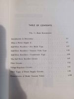
"Frequency Modulation Receivers" by A.B. Cook & A.A. Liff, 1968, 2nd printing, Prentice Hall, 527 pp. Shows light wear, pages clean, ex libris, never checked out.
"Radio and Television Receiver Troubleshooting and Repair" by Alfred Ghirardi & J. Richard Johnson, 1957, 8th printing, Rinehart & Co., 822 pp. Shows wear on hard cover, pages clean.
"Radio and Television Receiver Circuitry and Operation" by Alfred Ghirardi & J. Richard Johnson, 1957, 6th printing, Rinehart & Co., 669 pp. Shows wear on hard cover, pages clean.
"Radio and Television Receiver Circuitry and Operation" by Alfred Ghirardi & J. Richard Johnson, 1956, 5th printing, Rinehart & Co., 669 pp. Shows significant wear and fading on hard cover, pages clean.
"Basic Electricity/Electronics" Books 1 & 2, edited by Seymour Uslan, 1970, 1st edition 7th printing, Howard Sams & Bobbs-Merrill, Book 1 - 314 pp, Book 2 - 224 pp. Shows wear on hard cover, pages clean, ex libris.
$15.00 "Tube Substitution Guidebook" Antique Electronic Supply, 89 pages. Cover shows wear, pages are clean.
$15.00 "Newnes Audio and HI-FI Engineer's Pocket Book" by Vivian Capel, Heinemann Newnes Books, First edition, 1988, 190 pages. Shows little wear, pages clean.
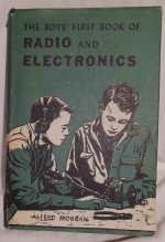
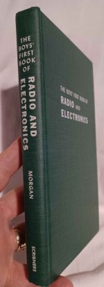
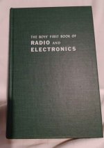
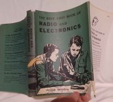
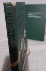
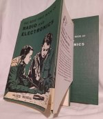
$50.00 "The Boys' First Book of Radio and Electronics" Alfred Morgan, Thirteenth Printing 1966. 230 pages. Shows light wear, dust jacket has few tears and wear, see images.
SOLD SOLD SOLD SOLD "Basic Electronics" Vols 1-6, by Van Nooger & Neville, Hayden Books, 1953, presumed 1st ed. Shows light wear, tear to dj, pages clean. SOLD SOLD SOLD
$6.00 USPS Media Mail shipping to USA
$12.00 Priority/UPS shipping to USA. Shipping fee covers any amount of books purchased. Will be packed with bubble wrap on all sides to immobilize in box and sufficient to prevent any damage from occuring during shipping. Shipped promptly, tracking shared, safely packed.
To make purchase message me with your email address and I’ll send you an invoice from PayPal, Venmo or Cash App. ]
Pick up in person welcome, no shipping charge. Litchfield IL