Pentode nonlinearity at low levels of drive voltage

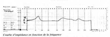
Datasheet plots of input voltage, current, distortion and power output have a curious nonlinearity at the origen of the input voltage curve. The plot usually rises steeply and then bends slowly to form a (somewhat) straight line for most of the graph. This implies that power output is not linear for very low input levels, becoming (more) linear only at higher input voltages.

What is the reason for this behavior? It is present for different tubes, different manufacturers, so seems intrinsic. But I don't recall reading any mention of this effect.

It would seem to imply a kind of compression for very small signals.
Charging up a capacitance comes to mind, since there is linearity at higher levels.

Am I just not using the right words and search terms?
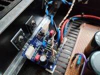
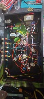
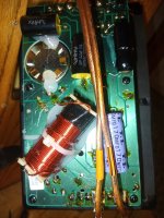
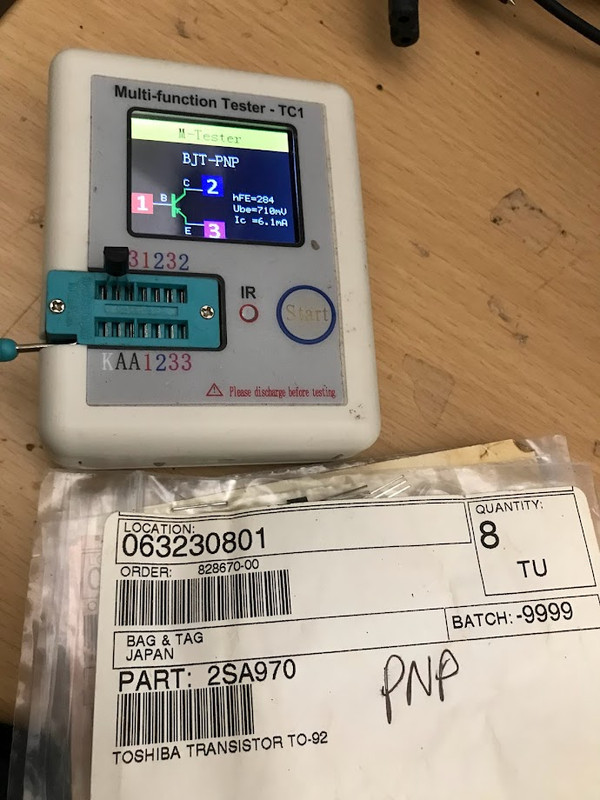
Sony TA-1010 motorboating

This is my first post here and as Dutch is my primary language I want to apologize in advance for my Dunglish 😉

I'm busy with a Sony TA-1010 that had several problems and by now is driving me mad. When I got it there was a loud buzz so I didn’t test it thoroughly as most of the time the basic things like replacing bad caps and cleaning already solve a lot of the problems.

Some of the things I have done already:
  • Cleaned switches and pots
  • Replaced the volume pot as the old one was too far gone.
  • Replaced all electrolytic caps with Nichicon FG caps except the main power supply cap C135 (1000µF/63v) as this measured fine. Most other caps were on their way out with either a high dissipation factor or a high ESR.
  • Replaced C120/C220 .02µF tantalum caps for 0.22µF Nichicon FG caps
  • Replaced the trimpots with Piher PT15 ones as the old ones were fluctuating a lot. The pots are set at approximately the same settings as the old ones (measured them before adjusting them).
  • Replaced R152 (6800 ohm's) as it was cracked and the resistance varied

The problem I have is that the left channel is motorboating. It seems to be coming from something on the amplifier board. When I take away the left input and short it with a 1K ohm resistor the problem still persists. Probing around it looked like C125 was leaking as it measured around 600 ohms in circuit . I didn't have 370pF laying around so I replaced it with a 330pF but this didn’t solve the problem. The 600 ohms measurement is gone... As the right channel plays as it’s supposed to do I don't expect it to be a power supply problem.

Does anyone have suggestions where to look?

The smell of your hobby

22 years ago I let go this familly inherited hobby for electronics , but I realized that the thing that I like the most about diy electronics is the smell of old solder with old tree resin which is very different than today's solder, feeling almost like a religious church ceremony where the priest makes fumes burning all sorts of resins and it's not like burning aromating sticks...It's very different first because it happens once a week and only for 4 or 5 times during a 5..6 hours religious ceremony..Well I barelly attended one or two in a decade , but from time to time I desolder some components from 40...60 years old pcb's and I realize how good that old resin smell feels, almost like a lost religion habit, almost like real leather, unlike today's solder or flux.If I'd do a shoe once again I'd do it for the leather smell...well the glues are pretty toxic and bad smelling, but if you ever had around at least a few meters of real leather you know what I mean.Some like contact glue though... 🙂
I should've probably been a perfume maker...As I'm mostly single for two decades now I can only remember my mother's perfumes...they were cheap and never riveled my first girlfriend perfume that was about 300 bucks for 50ml cause she had rich parents...but I wonder why I never got involved with the perfume industry.I didn't like chemistry too much yet It would have been a feast every day, unless there's a danger of getting acoustomed and saturated with those smells too...I don't see myself a seller or user of anything expensive...mostly a manufacturer and experiment addicted guy so there wasn't much chance to get into this expensive smelly bussiness...Probably the real secret in life is the scarcity of very fine essences yet If I'd be a billionaire , I could buy all the most expensive shoes in the world, but once finished they don't smell much, could have some ladies using the most expensive perfumes though...I probably need to be a billionaire cause I'd need to pay for those damn perfumes...or I could just enjoy the smell of old good solder and real tree resin...cause I don't even wear leather shoes these days...although I have a pair of Church leather shoes for very rare ocasions...
Login to view embedded media

Recommend me a sweet 10-20W design

A plea to all you wise tube heads... I'm a constructor (not designer) looking for a design to build but am punch drunk at the number of choices out there. I need 10-20w into 4ohms. It must have great resolution, excellent transparency in the treble especially, and throw a nice walk in soundstage. The rest can take a back seat. I have experience of a KT88 PP amp which was a bit brash, also a triode strapped EL34 which was very good. The rest? No idea. I am willing to spend medium money on parts and take my time. Based in the UK. Thank you in advance for any words of wisdom.

Spice model for 811a A2 Grid

Hi!

Glad to be back after almost a decade, any one has a good spice model for the grid circuit of a 811A?

I'm using this at the moment and the grid current draw in A2 mode doesnt seem right.

At 430v @ 100ma, Vg +22, the model only draws 3ma, I believe from reading tubelabs comments in 2007, Ig should be like 20ma or there abouts.

any help is greatly appreciated


.subckt 811a 1 2 3 ;
+ params: mu=160 ex=1.317 kg1=1350 kp=100 kvb=1400 rgi=2000
+ ccg=2.3p cgp=2.4p ccp=.9p
+ a=1.6667e-10 b=-.0000002875 c=0.0001758333 d=1.275
e1 7 0 value=
+{v(1,3)/kp*log(1+exp(kp*(1/mu+v(2,3)/sqrt(kvb+v(1,3)*v(1,3)))))}
re1 7 0 1g
e2 8 0 value=
+{a*v(1,3)*v(1,3)*v(1,3)+b*v(1,3)*v(1,3)+c*v(1,3)+d}
re2 8 0 1g
e3 9 0 table {v(2,3)} =
+ (-1 1.1e-16)
+ (0, .6e-4) (20, 5.38e-4)
+ (40, 6.25e-4) (60, 7.41e-4)
re3 9 0 1g
g1 1 3 value= {(pwr(v(7),v(8))+pwrs(v(7),v(8)))*v(9)}
rcp 1 3 100k
c1 2 3 {ccg}
c2 1 2 {cgp}
c3 1 3 {ccp}
r1 2 5 {rgi}
d3 5 3 dx
.model dx d(is=70u rs=1 cjo=1pf N=180)
.ends

Ice power 200asc output problem

Hello i have an problem. I have 8 ice power 200asc amplifiers and only one have 100%output, next one have 70% , rest of them 5-20%. I have change all fouly tht capacitors, nothing have change. Measured for short all transistors, capacitors, diodes. Everythnik looks okey. Power supply section work properly and have 47vdc , +-12vdc. Where is the problem? Very thanks.
20230131_210334.jpg
20230131_210343.jpg

What are these drivers worth?

Should I purchase? These are for sale locally for 950.00.
Looks like a DIY Jensen bass reflex cab with JBL drivers and crossover.

Attachments

  • 306413848_6153566684659441_8680936155200139235_n.jpg
    306413848_6153566684659441_8680936155200139235_n.jpg
    140.7 KB · Views: 166
  • 328527436_882430189627606_4023857935650631680_n.jpg
    328527436_882430189627606_4023857935650631680_n.jpg
    420.9 KB · Views: 167
  • 328622994_870039080881615_3690498757863175902_n.jpg
    328622994_870039080881615_3690498757863175902_n.jpg
    565.9 KB · Views: 157

Vintage Magnevox turned new again

Hello all, thought I'd share my current project. I had some old magnevox speakers lying around, very old stuff and sounded quite poor (looking at the picture now I realize how funny that might sound). I've had a lot of parts lying around waiting to be used and figured I could save myself a bit of time building a new cabinet, and use the old junk magnevox. The exterior and construction of the cabinet are fine, so it just needed a new baffle.

20221231_131832.jpg

A new baffle was cut from fairly cheap plywood I had lying around. It seemed to machine fine enough and I wanted to keep costs low on this one given the cabinets cheap chipboard.
I have a DX25 inside a WG300, and some Peerless 160f25pro01, wg adapters were printed by a friend for free. Next up is mostly waiting on PE to get back to me on a potentially bad measurement mic, hopefully things will be warm by then and I can get some nice measurements to start working on the crossover.
Not sure about keeping the cabinet ported or sealed, will have to see what this driver likes in winisd.

20230103_123416.jpg

Recommend me: Optical(SPDIF) in, 20W stereo out, Class D IC

My desktop powered monitors have developed mains leakage on their ground and it's time they (or at least their PSU and amp) went.

I figured I might do some DIY on it. I really like the look of the automotive style ICs like these:
https://www.infineon.com/cms/en/pro...grated-class-d-audio-amplifier-ics/ma2304dns/

However, it would be awfully cool if I can expand my options and then narrow them back down to something I can pick up in "dev module" or "eval board" format to... well evaluate it. Initially skipping PCB dev and starting breadboards.

I know all the main manufacturers make these chips so there is a wide range. I'm just trying to pick a few options to start on. If I search for this area on Amazon or AliExpress (where I would usually look for eval boards) I obviously get all manor of snake oil rubbish... where it seems that the colour of the capacitors has more value to the buyer than the actual facts.

I know that TI, infineon et. al. produce their own "Evaluation boards", but they are prohibitively expensive if you are only making a one/two off device for home use. Chinese dev boards are fine for this purpose.

Actual requirements:
Input: Ideally Optical SPDIF. Less ideally, I2S, not really helpful Analogue line in.
I only need 1 input but if two or three come with the IC, I might wire em up.

Output: 20W RMS a side would do. I'll have it drive the existing monitors initially and maybe upgrade to a 2:1 later. So an output channel capable of "sub out" would be ideal (line level or amplified at 20W)
I only need 2 (+1 sub) channel output. If the chip comes with 4, I might never hook them up or I might add them as surround (which opens a kettle of fish on the input formats, so lets leave that for now!).

Power supply. I have up to 10 Amps of battery power DC 12-14V range. When that isn't available I can use a quiet DC brick.

Idea: Using resolution imaging techniques to recover signal buried 32bit ADC noise.

In imaging it's possible to recover information (and increase resolution) by using multiple images that are aligned and stacked. It also means an object (a signal) can be recovered from below the noise floor of a standard image.

1520233808578.jpeg


Here's one of my astro images. Note the four dots - they are stuck camera sensor pixels. The image object (a galaxy) is used as the reference point to align each of the images that exist slightly offset from each other.

This means you end up with a set of pixel (ie samples) in a grid that are aligned on top of each other. Not aligned by the grid but the central point (and image) of the galaxy (our signal of interest).

So in the same form, it should be able to have a low jitter generated signal, say 1kHz and then sample the FFT. Next move the 1kHz a small amount to the left and to the right, taking FFTs each time.
Next you create a FFT 10X the size, then take each FFT and scale it up 10X and stack (add the bins ) the central points of the generated signal right over the top of each other on the bin that represents the 1kHz bin. The dynamic and static noise will then shift around.

The result would be a more detailed FFT that has a lower noise floor. In theory you could calculate how many images it would take to get below the noise floor by a predictable amount (treating the random noise as gaussian).

A 24bit ADC could, in theory, recover more than 21bits. Although this is more of a long measurement thus subject to temperature drift etc.

Thoughts?

Furysub, Apache H15, or Jbell 2' cube

EDIT . The thread still goes
But the PRV 15SW2000 driver was choosen
Now is matter of time to set on a cabinet design.

Guys ,
I am still considering different options that I am learning along the way.

Just one thing
I don't need any extension above 100hz
And I don't care strange dips above 100 that's will shaved of by the drive rack.

3015LF is my choosen driver
Cause I can drive 3 cabinets per channel at around 2.5 ohms
So 6 cabinets total , 3 each amp side
With my current amplification

I have 2 options
Screamers furysub
jbell SS15

Love Jbell stadium horn...but 150lbs of ply and the size is deal breaker for my mobile gigs.
I want
1/2" ply for weight easiness and transportation

Since screamerusa site is down
I could not able to pull the last revision of the furysub , somebody build a box beside screamer and says it have some freq discrepancies so he build the apache instead.

Idk if somebody have a working drawing for the furysub.

So kapalite 3015LF 8 ohm will be used on all boxes.
What you guys can advice.

Pros and cons please.

Next will be the tops to complement the subs
What screamer used was the jbell top box? With the arrayed piezos?

Anyway i want to attack the sub cabinet 1st
Best.
Max.

Enclosure for Philips AD1255/M7

Hi' Everybody. I hope you all are having a great day.

I think my search for full range speakers have come to an end when I purchase my friend's "Philips AD1255/M7" speaker pair. Previously I bought a pair of Philips AD80800 and ended up with disappointment. However, I wanted to buy something that sounds closer to the AD1255/M7 because he gave them to me just to listen to them. I ended up buying them,

They came in a home built enclosures which seems pretty old and not in very good shape. I am thinking of either building a new enclosure or getting them back in good shape for the time being.

Any recommendations for an enclosure build that suits a 12 inch Philips full range speakers...? I'll be glad to look into them, get them built.

Tomorrow i will try to post some photos of the enclosures I currently have so I can get an Idea from you.

The current enclosures look a little like the one in the photo Which I have attached.

The large boxes have two extra drivers "Highs and Mids" with a crossover inside, They were in bad shape so i disabled the crossover and put a direct wire. Box doesn't have a bass port as well.

I don't know much about speaker enclosure building, but I do have a person who can do modifications or build them, Should I add a bass port to the bottom? Will it improve the sound or having a sealed box is better for them?

Attachments

  • Lorenz-LP-312-12-full-range-speakers-in-_1.jpg
    Lorenz-LP-312-12-full-range-speakers-in-_1.jpg
    33.7 KB · Views: 856

Plitron toroidal part number deciphering

Hi, I have a busted Plitron toroidal transformer in my Furman ri-1220 power conditioner (unit dropped in shipping, ceramic center ring broke). I’m trying to find a replacement, but with Plitron having been acquired by Noratel years ago, figuring out the specs is a real challenge. Can anyone help me decipher?

7930-X0-05 #200430 F:60
Input: 120 VAC CLASS F (155degC)
P/N 500259-3314 Rev.E

Or is there a cross reference Noratel part? (Already emailed Noratel US sales office to ask)

Thanks!
EB

Attachments

  • B451D9F3-1F03-4C36-92FD-D159051B2FB8.jpeg
    B451D9F3-1F03-4C36-92FD-D159051B2FB8.jpeg
    350.9 KB · Views: 86
  • 6507DBDC-2911-4532-A8FE-566CA8F33088.jpeg
    6507DBDC-2911-4532-A8FE-566CA8F33088.jpeg
    681 KB · Views: 89

In search of a Y throat adapter

Hi,

currently I'm converting a 770 transistor Leslie cabinet into a tube powered 160 W one. As I didn't find any mid-range compression driver that could cope with this power, I decided to install two Monacor KU-516's. These drivers feature a 1 3/8" thread. Are there any adapters that allow connecting a pair of them to the rotating Leslie horn? Four bolt flange mounting to the spindle plate would be preferred.

Best regards!

Ampeg 300W SVT. Can I run it on 2 6550 tubes (instead of 6)? With mods.

https://ampeg.com/support/files/Schematics/S Series/SVT (1972, 6550 tube)/SVT 1971 6550 Schematics.pdf

I see two problems...
1. The plates will be running even higher than the already high 695VDC due to less tubes pulling the voltage down. No idea how tubes would fair at say 750+ VDC but probably pushing it.
2. The OT's impedance will be mismatched.

The possible problem solutions I see here are:
1. Plate voltage
a. use a separate power transformer for the plate voltage on the power tubes. This will also mean the bias will need to be different. I have no idea what kind of current the grid bias draw is, but I'd think this could be dealt with by divider resistors being adjusted to alter that voltage.
b. maybe an easier or cheaper solution than a. could the original power transformer be used, but voltage dropped somehow? Maybe a solid state relay with PWM.
c. I have no idea here but one other thought... tube rectifier(s). I seriously doubt there's any tube rectifier that could deal with this kind of power... but maybe one other alternative?? EDIT: forgot about the rectifier heater supplies. Possible maybe, but not at all practical.
2. OT Impedance mismatch
a. change the wiring of the speaker cab to get the impedance up to 3x what it originally calls for since we'd have 1/3 of the tubes and roughly 3x impedance on the output transformer's primary side.

Probably a little crazy to consider this, but it'd have a few advantages:
1. Less cost (and abuse) on the power tubes over the life of the amp.
2. Crank an actual SVT without having to be at crazy power and volume levels.
3. Still owning an SVT that could be put back to stock power later if needed.

400V on triode wired EF86 during startup?

Hi,

I´m about to rebuild an old PC86/6AV5GA SE amp to use more commonly available tubes like EF86 and 6L6GB/C/whatever. The raw B+ is around 400V during startup and I want to replace the messy Mosfet capacitance multiplier in the PSU with a simple choke. Adding an IDH tube rectifier to get delayed B+ is unfortunately not an option.
I'm sure the output tubes can handle 400V without any stress but I'm a little nervous about EF86 in triode connection.
I'm planning to sell the amp so I want it to be quite reliable.

Best regards,
Daniel

Help putting an old tube tester back into service

Hello,

Found a tube tester hidden away and covered with dust, its probably not been touched in 15 years or so when it was moved there and put away. I was really happy to find it because i have a lot of unknown tubes that id like to know if they are good or not.

Is there anything i should be careful of when trying to put it into service again? It seems to be pretty much just a network of switches, with a few resistors and a coupple of caps. Should i do anything more than test the caps and give the switches some electronics cleaner? Can i use it to find "matched sets" somehow?

Here is the model of tester i found: https://www.vintageradio.nl/Diversen/tech_tc2_tube_tester_engels.htm
The schematic is on that website, i am unsure if i could repost it here so ill just link the page.

edit
And what about testing tubes that are not in the manual? Like the 6DJ8/ECC88?

Thanks for any help 😀

V = 2,9*At*R, R and V are unknown

Been sick with influenza, pretty much stuck in bed for eight days, so been researching and attempting to design a BLH subwoofer. Having done so much research, looking at and reading so many pages, I am forgetting where information has come from. Being I have a Macintosh without VMWare and don't want to take time and space for a one time need, doing the calculations by hand; I love mathematics so it is fun. At this point, I am trying to calculate the volume using:

V = 2,9*At*R, where R is the distance where throat area has doubled.

At=(2pi*Fs*Qts*Vas)/c
I found this paper: https://www.passdiy.com/pdf/KleinHorn.pdf. It gives the formula:

Area at x (which I will simplify to Ax)=At*e^(4π*x/λ).

I graduated High School almost 27 years ago, so took me too much time to find how to bring down the exponent, spent an hour solving for x, however, the value is clearly not right. Can someone please help?

My solution for x is as follows:
Ax=At*e^(4π*x/λ).
Divide by At, giving:
Ax/At=e^(4π*x/λ)
According to this: https://www.wtamu.edu/academic/anns/mps/math/mathlab/col_algebra/col_alg_tut45_expeq.htm, we are to take the natural log.
ln(Ax/At)=ln(e)*(4π*x/λ)
But this: https://mathinsight.org/logarithm_basics says to take the log.

Neither resolves the conflict.

Since ln(e) = 1, provides more beautiful and elegant formula, so use that until know which is correct, giving:
ln(Ax/At)=4π*x/λ
Times by λ gives:
x=(ln(Ax/At))λ
Divide by 4π:
x=((ln(Ax/At))*λ)/4π

Since R is the distance x where Ax = 2*At, therefore:
R=((ln(2))*λ)/4π

Therefore
V = 2,9*At((ln(2))*λ)/4π)

Let us use a Faital Pro 12FH500.
At=(2π*Fs*Qts*Vas)/c
=(2(3,14159265359)*45cm*0,0873)/343
=0,07196353784m^2
=719,635378cm^2

Then assume a tune of λ=40Hz, so the wavelength is 858,04cm.

Therefore

V = 2,9*719,635378((ln(2))*858,04)/4π)
V = 98771,9515445cm which is clearly incorrect.

So then where did I mess up, please?

Anyone happen to know the formula for calculating volume?

Thanks in advance! 🙂


PS This is an example of my obsessive personality, I should have been in bed over three and a half hours ago... 🙄

Power limitations for LLC-smps for amplifier

Hi.

I'm a newbie at SMPS and LLC in particular, but with the aid of the app-note An1160 I have managed to get a simple LLC prototype running. I don´t claim to understand every calculation in the PDF, but I put it all into a spreadsheet and it puts out values that are similar to the values calculated in the example.

https://www.infineon.com/dgdl/an-1160.pdf?fileId=5546d462533600a40153559a85df1115

The target is to power a bridged amp with +/-30V driving a single 8Ohm speaker to around 150W (100Vpp).
So peak-current is around 7A, and average is like 1A for music

I'm using a L6599 controller in a standard setup, IRFP450 (overkill, but I had them), and a ATX-transformer-core with a airgap in the center-leg.
Transformer x-section is around 1cm2 and prim-sec windings are side-by-side to integrate all magnetics into one. I have tried dual, triple and littze-wire for primary and although it changed the internal heating a little it does not affect the output power

The LLC works great up until approx 60V into a 22Ohm dummy-load (60^2/22 = 160W).

But when its loaded with 12Ohm (60V/12Ohm = 5A) for just 10mS the voltage drops to around 40-45V and it struggles to maintain soft switching.

Now the ATX-core and the windings will probably never supply 60V@7A for more than short pulses before the heat rises, but it needs to supply the peaks in the sine.

I have tried different resonant-caps and different airgaps. This result in different minimum switch-freq to maintain soft-switching, but it dos not affect maximum output current by much. Also tried to add more sc-windings with little luck.

Depending on the airgap the prim inductance is around 500uH (250uH with shorted sec). Prim-inductance can go from 1500uH to 250uH with airgaps from 0.1 to 1mm with around 50 prim turns.

So, any ideas?

Kind regards TroelsM

For Sale Lazarus Cascade Classic Tube Preamplifier - $629

This is a very cool valve-based preamplifier, with lots of inputs and outputs, all in a low-profile rack-mountable form factor. It uses 12AX7 tubes throughout.

As shown in the photo, it has dedicated Tape, Aux, Phono, CD, Video, Tuner and Phono inputs, with Main and Tape Outputs.

The only odd thing about it is that the standby feature is a bit counter-intuitive, but it all works. Sounds great too!

$629 + freight. Shipped in original carton. Check or money order preferred.

Attachments

  • Lazarus front.PNG
    Lazarus front.PNG
    476.2 KB · Views: 134
  • Lazarus top.PNG
    Lazarus top.PNG
    1,010.3 KB · Views: 140
  • Lazarus rearPNG.PNG
    Lazarus rearPNG.PNG
    622.6 KB · Views: 135

SEAS A26 in oversize cabinet

I ordered the SEAS A26 kit (mid woofer and tweeter) and am about to build the cabinet (aperiodic) which is specified at 28 l. volume.
I'm mostly after the above 80Hz spectrum as the bottom two octaves are taken care of by my distributed bass system.
I've been thinking of increasing the cabinet volume but mostly for the soundstage enlargement sake, not bass.
I will appreciate any thoughts, opinions, advice on this idea.
Real life experience cases also appreciated.

Pro-Ject Phonobox MkII - no sound

This is probably a shot in the dark and/or a vague and unhelpful question but -

I recently got a Pro-Ject phono box to hook up a turntable to my focusrite soundcard and monitors, to listen to and record vinyl.

Bought it second hand (perhaps my first mistake) and it didnt come with a power supply. I tried an adapter I had that said it did a range (15-22v or something IIRC) and the phono box wants 16V so i thought it might work but it didnt. Bought a power supply new that is sold as being correct spec specifically for the preamp, still no signal coming through.

My question is whether i fried it with the first PSU or whether there are any other simple things i might be missing or components to poke inside with a multimeter that might diagnose the issue, dont want to chuck it but not exactly where to start with fixing it, aside from taking it to a repair person.

NB - when its all hooked up, theres a slight pop through the monitors when i plug in or unplug the sound, so there is something getting through, just not my music! 🙁

Any leads most welcome 🙂

High Quality Passive PA Speakers?

My reference speakers used to be Gedlee Summas. I sold them a few years back, they were just too big. Great sound, huge speaker.

A few years later, I bought some Yamaha DXR12s. The DXR 12 is a prosound two-way with a 12" woofer and a very nice waveguide. The Yamaha uses the same compression driver as my Waslo Cosynes. So it's been nice to be able to do A/B comparisons of the two, and get some inkling of how a wooden unity horn compares to a plastic waveguide.

My wife has banished all of these speakers, because they really don't work with the decor in our living room. (The Cosynes are for sale in the swap meet here.)

I've been buried in work for two straight years now, and probably spend 5X less time on DIY than I used to.

So....

Are there any good prosound speakers that are passive?

I came THIS close to buying a set of DXR10s this morning. The cabinet is about half the size as the DXR 12. Compression driver is the same, I think the amp is the same too.

I don't have any real complaints about the SOUND of the Yamahas. But they don't fit in the decor.

If I could find something passive, there are two advantages:

1) I may be able to remove the guts of them and put them into a knock down plywood cabinet from Parts Express, a cabinet that I could veneer and make it look nice.

2) My DXR12s have a nasty hum that's really distracting. Not a huge deal for a nightmare or club, super annoying for a living room. I know that I could run balanced connections instead, but my living room already has a mess of distracting cables and I don't have the time or energy to route everything through the walls.

Teac V-5000 cassette deck's take up spindle (the fwd spindle) stops rotating randomly in the middle of play

Hi,
I purchased this casette deck used on ebay, but in excellent condition. It has this problem.
Cassettes play and record satisfactorily. However I have this annoying problem.
Usually in the middle of play, the take up spindle stops rotating in the middle of the play and then
deck stops playing. I turn off the deck, or even fast fwd or rewind the cassette. Then when pressing play, the playing starts, then shortly after that, the take up spindle stops rotating and the play stops. I don't have a service manual of it, but I have good understanding and technical skills. I am an engineer.
It appears it has 3 motors and 2 belts. I havent opened the case yet. Could this be a worn belt problem, which may be easy to replace,
or more of a logic control issue? Has anyone experienced such thing?
Thank you in advance for any help.
Dinu

Tapped Port Modelling in Hornresp

Hi Folks,

I am intrigued by a few cabinets available for the bass guitar player that are more or less conventional shelf ported designs that have the woofer mounted in the port firing from one side to the other.

One such example is the Bill Fitzmaurice Omni 15. I own one of these and the bottom end is quite spectacular. The port is flared, and the space behind the baffle is completely open (that is to say that its just a reflex box with a flared port and the woofer mounted in the port

1675127889533.png


There are other examples, such as the Boom Bass Cabinets that have a second woofer firing downwards into the slot port.

1675128565675.png


I believe that the two woofers in this box share the same airspace, But for the sake of this post, lets assume the front facing speaker is a sealed back midrange.

How would I model such a beast in Hornresp? I've tried modelling them as a tapped horn but can't seem to get anything approaching a normal looking output.

The BFM Omni 15 is a great box in the low end (it has a pretty undesirable midrange), so I would like to understand how to model these beasts to see if I can tailor them to drivers I own.


Can anybody help?

FS: Hiraga LeMonstre clone Class A

Selling in excellent conditions hiraga amp clone. See pictures . Ship to Europe only. 350eur or best offer. Smooth and warm sounding amp in classe A.

Attachments

  • IMG_20221226_113036.jpg
    IMG_20221226_113036.jpg
    203.5 KB · Views: 400
  • IMG20221222132341.jpg
    IMG20221222132341.jpg
    129.6 KB · Views: 422
  • IMG20221222132236.jpg
    IMG20221222132236.jpg
    253.8 KB · Views: 432
  • IMG20221222132308.jpg
    IMG20221222132308.jpg
    367.8 KB · Views: 435
  • IMG20221222132316.jpg
    IMG20221222132316.jpg
    220.7 KB · Views: 392
  • IMG20221222132610.jpg
    IMG20221222132610.jpg
    123.5 KB · Views: 404
  • IMG20221222132215.jpg
    IMG20221222132215.jpg
    234.6 KB · Views: 392
  • IMG20221222132231.jpg
    IMG20221222132231.jpg
    374 KB · Views: 410
  • Like
Reactions: Pano

KEF Reference Model Three Schematic

I am looking to do a complete crossover rebuild for my late 90s Model Three.
Was wondering if anyone has or knows where I can obtain schematics with component values. I want to build a fresh pair of x overs with poly caps, better overall parts quality using point to point ect, Then keep the originals untouched I can put back in if I ever decide to sell. The speakers are the original versions not the three two with boundary compensation.

Thanks in advance.

PCL82 Amp Build

I have been busy building a PCL82 based amp with EM84 dancing indicator valves.

Based on stephe's 6BM8 amp design.

Reusing parts so didn't have the option to ultralinear the output. Nevertheless the result is rather nice sounding, especially combined with a little subwoofer I have rebuilt using a cheap Chinese plate amplifier.

A little cheapie passive tone board provides volume, bass and treble control and seems to operate really well for very little effort 0 money.

Currently using shade feedback resistor of 220k not sure if I should up this given the lack of ultralinear.

Cheers

Attachments

  • IMG_20230120_055549.jpg
    IMG_20230120_055549.jpg
    235.1 KB · Views: 173
  • IMG_20230122_143150.jpg
    IMG_20230122_143150.jpg
    290.2 KB · Views: 168
  • Like
Reactions: Fuling and decramer

For Sale Some nice stuff. HP audio equipment, Semisouth, vFETs

Hi guys. I have reached to end of my diy audio path and I sell some nice things. So, I have one HP3580 in good state, working; one HP 8903B working too. And I offer two nice sets of transistors... four vfet sony 2sk82 tested and one 2sj28 (tested but I have not data when I did it). And I add to batch two 2sk183V. On the other hand, I offer four SJEP120R063 (fantastic for clonning of J2 or F2J).

vfets set ...... 250 eur + shipping + fees
SJEP120R063 ..... 240 eur + shipping + fees
HP3580 ..... 300 eur + shipping + fees
HP8903B ...... 300 eur + shipping + fees

hp1.jpg
hp3.jpg


hp4.jpg


vfet1.jpg


vgs.jpg


SJEP120R063.png

Grounding vintage amplifier to mains

Old vintage 1976(?) Harman Kardon 900+.

Just got done doing a very comprehensive restoration - all the caps, nearly every transistor, etc. Plays wonderfully, but still has a bit of annoying mains hum that comes through the speakers. Not very loud - don't even notice it when music is playing - but it is considerably louder than just about any other vintage gear I have owned.

I can power this thing using my bench supply and it is dead-quiet. I been looking around and it seems these old HK receivers were prone to humming noise.

One guy - who seemed to be a former HK repair tech in the 70's and 80's had mentioned some of this was eliminated by re-routing a ground wire that runs by the tone board - but he has seemingly been offline since before the pandemic (gulp).

Another person (maybe it was here) somewhere had mentioned also having a 900+ that always had a bit of hum when the bottom cover is installed. I do notice the hum slightly more when the cover is on mine, too.

But the real reason for this discussion is: I notice that there is a 2.2M ohm resistor that connects one side of the AC power cord directly to the chassis ground.

For those who do not know... on this particular model, ground is ground is ground. Signal ground, power ground, chassis ground... is all one ground. Also seem to be a couple potential areas for ground loops from what I see and understand of the schematics.

Since the ac plug on this stereo is non-polarized... it seems to reason that the "ground" on this unit could be connected to either side of the AC line (nuetral or hot).

Would there be any harm in removing this 2.2M resistor bridge? If not, you think it is likely to help any of the hum feedback I am getting?

If I unplug this unit while powered on, the humming stops instantly. Keep in mind: it will continue to play music for 3-4 seconds after unplugged due to the large PSU caps. So the hum is certainly coming from the AC line.

Another thought: would it be of any advantage to install a grounded plug on thus unit? Or is connecting chassis ground to earth ground not a good idea?

-Dean

Deoxit???

I'm building a pair of loudspeakers that are intended as heritage cabinets which I hope will outlive me (at least as furniture). I'm paying great attention to crossover assembly, internal wiring, etc., but at some point I'll be sealing up the boxes (although access will still be available by pulling the drivers). I've heard that Deoxit can be helpful in deterring corrosion. I'm not familiar with Deoxit other than as a spray-on contact cleaner...does anyone have any experience with it as a corrosion preventative, and are we talking about Deoxit Gold or something else?
Thanks!

thermistors in crossover

I have a pair of Triangle Celius 202 (vers 1) that has two thermistors per speaker on the crossover pc board.

I rebuilt them using better parts (caps). At that point I thought the thermistors were just their way of having a fuse in circuit to protect the drivers. I read in one place to leave them and in another to pull them and replace with wire. So of course I measured the resistance at 72F and replaced with mills 5w of those values (.62 & .75 ohms). So everything was good except one of the caps I added failed after a few years, so when I opened up I figured, hey try the straight wire change on one.

It's very different, very bold and louder sounding (that's a lot resistance taken out), but the depth seems gone - the other way they sound like very stately dipoles. Coherent, flat, good depth, clean taut bass, but maybe too tame.

I know now the thermistors were to change resistance if the crossover got heated to a certain temp to keep the behavior of the drivers/xover in sync with the change. I dont know what the original values were, and Triangle is legendary for not dealing with products that are no longer made.

I don't listen loudly so the change over feature of the thermistor isn't a big deal, not enough to deal with it. So what's my recommended move here? I don't think an SPL meter will clue me in. Given no input I'll go back to the resistors back in.

Efficient Home Theatre Systems

Almost everything electrical in my house boasts its A+Energy Star rating except for the audio systems. If I take a typical big-box system: the JVC NX-F7 offer an SPL of 76db. Simply changing the speakers would reduce the power consumption at any given listening level.

Energy prices have doubled in my country. Throwing gazillions of watts at tiny speakers doesn't seem to be the best way forward. It seems bizarre that, when cranked-up, my sub consumes more power than every light-bulb in the house.
Has anybody considered efficiency as a primary design concern?

Hopefully, I want to build something in the Spring.

Any ideas?

need some help for testing my Sony TA4650 vFETs

Hello ,

Sorry for my Englisch.

I Have / had a nice working sony ta 4650.
I did the diode mod.
And after this mod my sony did not work any more.
So i have test the vfet 2sj18 and 2sk60.
did remove them from the Amp.

i have test them with a vom meter
i think the 2sk60 are not good any more
how can i test them ?
housing to G is 60 ohm
housing to S OL
G to S OL

Are they defekt ?

Thanks for help ore info.

Bart Wolters.

Extreme Outdoor Speakers

I am looking to upgrade my backyard system. I currently have Apollo MTMs that are not cutting it. My plan is to have four 18s for subs and 12” tops (either coaxial or waveguide). These are not just party speakers as I would like to do critical listing so sound quality is #1 But of course I want the ability to crank it. My budget is around $250 per sub driver and $500 per top. I have two NU6000‘s to power the subs and a XLS2500 for the tops. I would rather go passive for the tops but I have not found a kit that will work for my application and I am not good at crossovers. All drivers will need weatherproof cones. They will be out of direct rain. I have a front yard system that has four PA380’s and two HTM10s that sounds very good but I want better for the back yard. Listing to music out in the open with no walls or reflections is as good as it gets. I’m in the county so neighbors are not an issue. Please given recommendations. I am leaning towards Faital drivers as they are mostly waterproof.

F5 Turbo self-oscillation in low frequency

I'm finishing assembling my second F5 Turbo in a hybrid version, a V2 with transistor V3 driving.
the power rail increased to 39V with mosfet stabilized power supply.
During the tests I noticed a self-oscillation on my analog instrument connected to an 8ohm load when injecting a sine wave signal below 120Hz.
The blocking capacitor (C3 C4) for the self-oscillations I have tried various values from 560pF to 1.5nF the self-oscillation remains. Has anyone noticed a similar thing on their F5? Thanks to all who want to participate. Sorry in advance for my english google translate

Question about Lundahl transformers from a complete noob

I want to build my first ribbon mic and I have everything except the transformer.
I don't know anything about transformers but I do have a friend that told me he can make any transformer from scratch as long as I give him every technical detail required.
During my research from years ago I kept hearing about Lundahl transformers being some of the best for this job (like the LL2912).

My question is, why are transformers like these so expensive in particular?
Additionally, I cannot find any information online such as number of turns and wire gauge/materials to attempt to replicate them (a.k.a. buy the materials and throw them at my friend).

Is achieving the quality of these transformers virtually impossible without spending close to €80-90? Should I start experimenting with cheaper builds?

Orion HCCA5000.1D

This amp came with shorted outputs so I replaced them and the IR2110S. With the outputs in the amp I have rail to rail oscillation but it goes from 140volts to 40 volts and starts to draw 9 amps. With the outputs out I don’t get any low side drive unless I short pins 6&7 on the TL072.

Attachments

  • 6F0C4634-2066-45BF-970A-495D4538945C.jpeg
    6F0C4634-2066-45BF-970A-495D4538945C.jpeg
    732.6 KB · Views: 106
  • D7A6A5ED-E8AA-4AEE-9446-5F15FC5FB1C3.jpeg
    D7A6A5ED-E8AA-4AEE-9446-5F15FC5FB1C3.jpeg
    501.8 KB · Views: 94
  • 1CF4C9C4-8C8F-4E4F-94F4-EC1289F7437A.jpeg
    1CF4C9C4-8C8F-4E4F-94F4-EC1289F7437A.jpeg
    517.8 KB · Views: 96

Optical to Coaxial digital out-how to? (Denon CD player dcd-700AE)

Hi all,

I am in a position to get used CD player Denon DCD-700AE in fantastic condition for cheap. Only problem is it has optical out instead of coaxial S/PDIF that my DAC has.

Looking at the attached schematic I`m a bit confused. I can see digital out from the DSP chip TC94A14FA and then to 74WHC157 multiplexer before it meets TC7SHU04 (inverter/unbuffer-powering led diode?).

At what point (and if it`s even possible) to tap a spdif signal and route it through 75Ohm coax? I actually want to use BNC connectors for this, but that is beside point here.

Unfortunately I am not an expert in digital electronics or S/PDIF protocol so your help would be greatly appreciated, thanks!

DENON DCD700-.png

Help with these speakers

Yesterday i came across these speakers which immediately bought because they are full range drivers ans i was looking for a pair to build a set of speaker boxes. It says dew dortmund and that's all. Does anyone have information about these speakers? How good are they...?

They sounds wonderful when i hooked them up to my sansui au-alpha 999. However one speaker still needs some repair i think, i better take it to a professional speaker repairman to get it done right.

Any suggestions on how to fix it? You can see it in the photos, the one with damage gives a strange rattle.

Attachments

  • IMG20210322101714.jpg
    IMG20210322101714.jpg
    623.8 KB · Views: 696
  • IMG20210322101653.jpg
    IMG20210322101653.jpg
    609.9 KB · Views: 612
  • IMG20210322101648.jpg
    IMG20210322101648.jpg
    690.6 KB · Views: 629
  • IMG20210322101724.jpg
    IMG20210322101724.jpg
    582.4 KB · Views: 607

oversizing an enclosure; à la Le Petit

does anyone any insights on designing oversized enclosures for single driver speakers?

as i understand it, when he made Le Petit, Hiraga used a big port to boost frequencies below that of the resonant frequency of the little fostex but i dont understand his reasoning behind the size of the enclosure, and i read the original L'Audiophile article.

please no critique of the design itself (dave 😉 but i would like to hear how people approach making oversized enclosures for single drivers.

  • Locked
Forum suggestiion/question - repository for manuals

Is there an easy way for the admins/designers to create a repository for manuals or links to them? this has probably been asked before. seems like there are many threads with manuals attached, sometimes deep within the thread. now that hifiengine won't allow downloads for a lot of people, just see the thread What is going on with HifiEngine ?

https://www.diyaudio.com/community/threads/what-is-going-on-with-hifiengine.385444/latest

On upgrading Infinity Kappa's 9.2i

I have been thinking about doing some upgrades to ma Kappa's 9.2i.
Then I looked at the crossover and had a second thought! It just seems very well made. The speaker cables also look descent.
Many other Infinity speakers have a back placed tweeter. I once had a pair of Sigma's and always liked the highs on them. I think it was because the tweeter on the back. It just filled the room in a nice way. So maybe doing the same on the Kappa's? Installing a back mounted tweeter?

Have some of you here ever done any modifications and improvements on those speakers?

Attachments

  • IMG_20230131_181816_798_1.jpg
    IMG_20230131_181816_798_1.jpg
    511.2 KB · Views: 578
  • IMG_20230131_181836_565_1.jpg
    IMG_20230131_181836_565_1.jpg
    499.7 KB · Views: 296
  • IMG_20230131_181854_754_1.jpg
    IMG_20230131_181854_754_1.jpg
    414.6 KB · Views: 560
  • IMG_20230131_181909_176_1.jpg
    IMG_20230131_181909_176_1.jpg
    417.9 KB · Views: 362

Alternative USB to I2S DAC similar PCM2706 ?

Hello Forum,

I'm trying to build my own IcePower 2.1 amplifier setup with a self designed DSP board at it's center. So far, I'm progressing well. My first test setup is working and I have identified some points I would like to improve. One point from this list is an USB input. So my amplifier should be wokring as a simple USB soundcard under windows. Should not be a problem. I could use a PCM2706 chip form TI to archive this goal. But the PCM2706 seems to be outdated. Yes it supports 48 kHz, but as a Hifi enthusiast my heart is screeming for 192 kHz sample rate. You know for reasons.

Any suggestions which IC I could use a a simple USB to I2C DAC / Bridge? USB goes in, I2C comes out and is routed to my DSP IC. That would be all the functionality I need from it.

My first amp build. Need some guidance. Icepower 1500S PSU + 400A (x4)

Hello everyone.

I recently decided to build some high end 3 way floor standers using the SB Acoustics Santori Textream series drivers (tweeter/midrange) and SB Acoustics 8" SB23MFCL45-4 (woofer x2). I will post that build in the multi way speaker part of the forum in the coming days. I have always designed my own passive X-overs for the speakers I have built in the past but this time I decided to go active after purchasing the Dayton Audio DSP-408 and giving it a listen and liking it. So this meant I would be needing separate amplifiers of course and rather then hobble together something from the hodgepodge of different amps I currently own, some good some not so good, I decided I would try my hand at building a class D amp using amp modules. Simple right?

So after doing a ton of research on what's available and what I could afford I decided I would go with IcePower. They have a good reputation for quality products and they aren't exorbitantly expensive like the Purify offerings. After going through their catalog I decided on the 1500S PSU and the 300A amp modules. After ordering them I was informed that the 47 volt version of the PSU needed to power the 300A modules was out of stock and It might be a while before they got any more and they suggested I use the 69 volt version and the 400A modules all of which they had in stock and could sell me for the same price. I went with their suggestion and that is what I now have 1- 69 volt1500S PSU and 4- 400A amp modules. (I will attach the data sheets below) So I have a lot more power then I will ever use when driving these speakers but the extra head room is welcome.

So now on to the build. I picked up a new case from the DIY store here. It's a pretty nice case made in Italy and should suit my needs just fine. I also ordered all of the necessary wiring from IcePower when I ordered the other stuff so I have that. I ordered a power switch for the front of the case along with some LED's. I ordered some RCA's for the inputs, (I'm going single ended for inputs because that is what my source and DSP unit have.) The rest of the things I already have.

After thinking about it for a while I decided on the layout of the components. I plan on putting the DSP unit inside the case to cut down on the amount of interconnects that otherwise make for an unsightly mess outside. So far, as of the writing of this post I have the PSU and all four of the modules mounted in the case along with the DSP and some shielding to separate the back side of the PSU from the wiring coming from the DSP as it is mounted above the PSU. I also have all of the wiring going to the 69 volt +/- rails hooked up. I have drilled out the back plate of case for most of the connections I will be using and have installed the speaker binding posts, in this case they are sockets for banana plugs. It is here that I find my self needing some answers to some questions that I have.

1- So first question relates to Vdrive. The PSU shows it as an out put and the modules show it as an input so I assume these two connect together correct?

2- Next has to do with DVDD/DVSS and VDD/VSS. The data sheet says to only hook one or the other up but not both. I believe that VDD/VSS are +/- 5V supplies and DVDD/DVSS are +/- 12V supplies. I have no idea which one of these supplies I should hook up. Is there anything needed in between? (resisters, capacitors, ect for current limiting and ripple)

3- Then there is some confusion with how the PSU starts up. The data sheet says:

ICEpower 1500S will start operating in disabled mode when mains power is applied to the module with only DVDD,
AVDD, AVSS and Vdrive running. Thus, to enable the main converter an external enable signal is required, or a pull-up
from DVDD to PSU_Enable. For more advanced applications, a wide set of control, status and monitoring inputs and
outputs are available.

My assumption is that you need the signal from DVDD out to jumper to the PSU_Enable input to start the unit? This also brings up how to incorporate the DSP power up function into the amp. It has 4 pins. 12 volt power, ground, 12volt trigger in and 12volt trigger out. I want to use the 12 volt trigger to enable the DSP as opposed to RCA sense as it is to flaky. So do I use the DVDD or VDrive to power the unit. I assume that I hook the 12 volt power and the 12volt trigger in to the same source or is there a better way of hooking this up?

4- This has to do with bridging one of the amp modules (BTL). The data sheet says:

12.4.2 BTLselect input
The BTL mode synchronizes the two SE channels to avoid idle tones and to improve the performance when driving the
two channels in BTL. To enable the BTL mode the BTLselect, pin 8 on connector P7, needs to be pulled high.
In BTL mode invert the polarity of channel 2 relative to channel 1, as illustrated in Figure 28.

There is a PullUpTo5V pin on the P7 connector. Do I just connect that to the BTLselect pin on the same P7 connector to enable BTL operation along with the audio input connections which I understand?

I have a couple of other questions but I will inquire about those a little bit later as I'm already asking for a lot of information here and I don't want to overwhelm anyone including myself. So yea I would appreciate any help I can get here and hope not to be a pain in anyone's back side but like I said at the beginning this is my first attempt at assembling one of these and the data sheets are geared toward someone who already knows the terminology and speaks engineering speak. I'm a carpenter by trade so hopefully one can excuse my under qualifications in this arena.

I will include some photos here shortly.

Attachments

Powering up tube amp after sitting for 3-4 years

So I built a pair of the Uniamps designed by Pete Millett, They gave me fits with a low frequency oscillation but Pete helped me fix it. I only used them for about 40 hours when one of the Svetlana KT88s died, It must have been a leak in one of the pins all of the silver getter was gone. So they have set in the closet for several years until I decided to just buy a quad set of JJs to replace them. I have a variac should I bring up the voltage slow to give the caps (black gates) time to reform? How long and at what voltage would be good, I will either put a speaker or 8 ohm load resistors on it when I do this.

Thanks for your help.
Bill

By the way I will be open to offers for the 3 tubes, it is a shame they are much better than the JJs ,
Bill

Improved donations / membership upgrades system

I'm happy to announce that the donations / membership updates system has just been updated and cleaned up. Gone is the messy landing page with confusing options. In is a minimal and straightforward presentation. This is only a first step but I think it will go a long way to improving communication.

Firstly, thank you to everyone past and present who has contributed financially to support the operational costs of diyAudio.

Last year we engaged quite a bit of external development help. This allowed us to successfully move to this new, stable, secure platform (XenForo), with almost zero downtime and no significant hiccups since the migration. The new software and hosting configuration will enable us to meet the needs of the community over the coming decade, or two. If it were not for the generous donations towards operational costs from members, and the financial support from the diyAudio store, this would have been possible.

Here's what has changed today:
  1. All membership benefits are the same or slightly upgraded compared to what they were before
  2. We're now using the default XenForo upgrades system. Simple is sometimes best.
  3. Communication has been improved about what will generate a membership upgrade, how much it costs, and how long it will last for
  4. The entry level membership upgrade has been renamed from the ever-so-awkward "Aficionado" to "Enthusiast", and reduced in price from $25 to $20
  5. The also ever-so-awkwardly named "Connoisseur" level has been renamed "Patron"
  6. All levels now enable multiple recipient messaging
  7. The only difference between each level is more signature lines, and Patron level allowing commercial links, but we may add new features in the future.
  8. Members often reported missing re-subscription emails, or having problems re-subscribing. There are now recurring subscription options for each level for your convenience. Set and forget, but you can cancel at any time to stop the recurring billing. You choose what suits you.
  9. We have switched the system that sends emails to a new one, and the emails have been improved to help with better communication
What's coming in the future:

  1. This week there will be an update to the "postbit" (the part of the post where you see a member's name, avatar and their details) to add country flags. When this is launched the "donation star" is being changed to a more compact blue "donation shield" which better represents its purpose.
  2. Soon after this the "Enhanced Thread Print" system will get a bit overhaul to make it fit for purpose. The current post-XF implementation is not up to scratch (primarily, it can't handle very long threads).
  3. In the near term future, any member will be able to gift a membership upgrade to another member, should they be feeling generous
  4. In the medium term future, upgraded members will gain additional access to more forum visual customisation options, as time goes on (show/hide flags, various other requested niceties, more themes, etc). And other stuff we will endeavour to find and create to give you value. None of these things exist yet, so take this with a grain of salt, but we will be endeavouring nonetheless.
Again, thank you very much for your support over the years. Especially those who have re-subscribed year after year. Your contributions go a long way to the keeping diyAudio operational.

Jason.
  • Like
Reactions: krivium

Bypass loudness on integrated amp

I'm trying to repair a Sony F 630 ESD, from which the volume pot has broken off.

I know of ALPS pots that have a 4th lug, unfortunately I can't fit those between the PCB and the faceplate. I went for a normal 100k pot instead, not feeding anything back to the loudness circuit. Which results in a strange feedback and hum.

How do I overcome this? I'm confused on how the circuit works (see attachment). I'm guessing I can hardwire the source direct switch to a "always on" but I still want to keep the EQ

Attachments

  • Schermafbeelding 2023-01-24 om 20.16.15.png
    Schermafbeelding 2023-01-24 om 20.16.15.png
    355.8 KB · Views: 170

Firstwatt F3 preamp recommendations

Hi everyone!

i've been using a simple PP integrated tubeamp for the last couple of years but was always curious how a FW amp would sound, so i've been reading up on it the last weeks and searching the internet. accidentally i came across a used F3 clone and after some research and a good talk with the owner i decided to buy it. From all the FW amps i was the most interested in the F4 but that can be a project for next time. I will receive the amp in a week or 2 and now must choose what pre amp to match it with.

I am a novice DIY'er, i have decent soldering skills but not much electrical knowledge. i do read alot here and slowly do start to learn more. my speaker setup for the moment is a pair of cabasse sloop M4 speakers, 94 db. sealed, 12 inch woofers and presumably, going of old documentation from cabasse, a minimum of 8 ohm impendance as you can see in the attached picture.

I am looking for a DIY project, that is not impossible to accomplish by a novice and that will be a good match with the F3 amp. Ideally also a match with the F4 for futureproofing myself.

The most cost effective option i was looking at is the B1 korg pre. i still have to go through the entire thread, but at first glance the impendance is low enough and it seems to sound pretty good.
other options i thought of where the iron pumpkin pre, and the BA3 pre. The pumpkin looks great and i've only read good things about it. other recommendations are more than welcome btw
cost is a factor, so a cheaper option that is suitable and sounds maybe a tad worse but still matched wel with the F3 will be preferred.
So, if anyone has some experience or has some input on which pre amp will be the best match with the F3, i will be glad to hear it 🙂

I do like to have a bit of a tube sound, but is does not have to be dripping in sugar. Details, imaging, smoothness and 3D soundstage are the things i'm looking for.

Thanks for the help
Patrick

Attachments

  • cabasse-sloop-m2-nrds50-0981-2 (1).jpg
    cabasse-sloop-m2-nrds50-0981-2 (1).jpg
    19.8 KB · Views: 159
  • IMG_7481.jpeg
    IMG_7481.jpeg
    279.7 KB · Views: 177

For Sale 2SJ109 BL

2SJ109 BL

18 of them for $180
I’ve been sitting on them for over 10 years. I haven’t tested them so if for some reason these are not the real deal I’ll except a refund.
Free shipping.

Attachments

  • 9CE6EF12-4085-4506-9D27-8730A5B55670.jpeg
    9CE6EF12-4085-4506-9D27-8730A5B55670.jpeg
    162.7 KB · Views: 123
  • 1D3BB56E-0A33-4886-8056-FC0121C4D80E.jpeg
    1D3BB56E-0A33-4886-8056-FC0121C4D80E.jpeg
    280.3 KB · Views: 128

Reducing Secondary Voltage

New to this and I'm trying to reduce the secondary heater voltage on an amplifier I just finished...

The amp has a 6072 and 12AU7 that need 6.3V. Currently, the tubes are running a little high at 6.8V, so I am trying to bring it down a touch. These tubes are the only tubes on the secondary, it is not center-tapped and I would like to put a resistor in series to achieve this.

I've poked around online and found some info at http://www.valvewizard.co.uk/heater.html that seemed to be applicable to my situation. I've gone through the calculations and would love a second opinion(s) on my math.

The 12AU7 and 6072 draw .3A and .35A respectively and each needs 6.3V. I need to lower the heater voltage by .5V and have the following worked out.

Resistance: .5V/.65A = .769 Ohm

Dissipation: .5V x .65A = .325 W

Does this approach make sense? Haven't seen many resistors lower than 1 Ohm, so unsure how to move forward.

Thanks in advance.

Barrett Strong RIP

Barrett Strong February 5, 1941 – January 28, 2023. One of Tamla Mowtowns founding artists and contributor to many Motown hits.

Together with Norman Whitfield, he wrote some of the most successful songs released by Motown, including "I Heard It Through the Grapevine" by both Marvin Gaye and Gladys Knight & the Pips; "War" by Edwin Starr; "Wherever I Lay My Hat (That's My Home)" by Marvin Gaye; and the long line of "psychedelic soul" records by the Temptations, including "Cloud Nine", "I Can't Get Next to You", "Psychedelic Shack", "Ball of Confusion (That's What the World Is Today)", and "Papa Was a Rollin' Stone", amongst others. Strong and Whitfield also co-wrote the ballad "Just My Imagination (Running Away with Me)", a 1971 hit for The Temptations (the last single to feature original members Eddie Kendricks and Paul Williams).
  • Like
Reactions: pl802

Modifying diffuse speaker with twin tweeters to direct single tweeter speaker.

I have a pair of old Boston Acoustics VRM-X speakers that I would like to use in an Atmos surround setup. These speakers employs one active
woofer, a passive radiator plus two tweeters.

I would like to use these with a new cabinet, but only use one tweeter.
I have not had access to the crossover yet but would it be likely that this modification would be ok path to continue and achieve a good level match between the tweeter and woofers? I can open the speaker and take som pictures of the crossover to get a better understanding of what type it is.
I have a Dayton Dats V3 to measure the tweeter TS parameters.

Thank you.

Attachments

  • Boston Acoustics VR-M X.jpg
    Boston Acoustics VR-M X.jpg
    91.4 KB · Views: 94

Remix of Bob Dylan's Time Out of Mind

What is your opinion of the Time Out of Mind remix? RollingStone writes Michael Brauer was tasked with taking a beloved, Grammy Award-winning album.He went into the project knowing little about the creation of the album, so he was stunned when he pulled up the tracks and realized that 12 musicians were playing at once, creating a wild cacophony. Lanois had decided which parts to keep, and which to discard, during the mixing process.“Normally I just pull up the tracks and I mix, and all the ingredients are there, and I don’t have to think about arranging or re-arranging,” Brauer says. “In this case, I had to go through every section, instrument by instrument, and decide what I liked, and what I didn’t like. Once I did that, I’d go back and forth against the final mix and see what Lanois had done and kept, and see if it was how I’d done it or not. It was a very, very long process.”Brauer wanted to restore much of Dylan’s original vocal, while still staying true to the signature sound of Time Out of Mind. Luckily, Dylan’s master vocals had been recorded separately by Lanois, and preserved. “That meant I had control over how dry or how wet I wanted to make the vocal, which was great,” says Brauer. “Otherwise I would have had no flexibility, and there were many times they wanted more natural voice without as much amp sound.”

Any thoughts about the remix? I think it is better than the original Much more detailed with more instrumentation and Dylan is easier to understand. The elimination of what Dylan did not like about the album, the Lanois swamp sound. To me just an overall improvement that almost sounds like an new album.

Re-capping Denon HA-1000 mc headamp

Hi everyone, I recently purchased a Denon HA-1000 mc headamp. It's in great condition, working fine and sounding fantastic.
I opened her up and there is either some mild leaking of some EL caps but it could also just be glue. Most of the edges are really smooth so that probably means glue. There is one place where some crystals are showing so that area is probably from a minor leak. All the other caps show no signs of glue or leaks. The unit is probably from the late 70s or early 80s so some preventative recapping is not terrible idea.
I've found a schematic online and I'm looking at what I might want to change. I really like the sound so I don't want to change too much right away, but I am open to discussion if there is something (like improved voltage regulations) which could elevate the sound. In general I don't like the shotgun approach of changing everything at once. I'll just start with a few select locations where the caps could be leaking or stressed from age, or where I think a more modern cap can be an improvement.
My plan so far is to focus on the rather generic black wrapper chemicon larger caps. I want to do Panasonic FR for the outboard PSU (2200uf/35v: C4,C5), the larger rail bypasses (1000uf:C11,C12; 2200uf:C7,C8,C9,C10,C33,C34,C35,C36; 330uf:C13,C14) and I'm also thinking about Panasonic OSCON for the input blocker caps (470uf/6.3v: C1,C2,C3,C4) and maybe for the 1000uf at C15,C16 which I think might be part of the feedback loop. The input caps are too big a uf value for film caps, so I think OSCON is a reasonable upgrade. Since it is just a MC headamp there is no RIAA circuit.

I still need to measure the diameters of the caps and lead spacing so I am in no rush. I'm just at a planning and thinking stage now.

I'm searching for some discussion on the circuit. Is there some other parts I should focus on?
After the initial re-capping, is there some part of the circuit that could use an upgrade like improved voltage regulation.
cheers jeshi

Attachments

  • Denon-HA-1000-schematic_20220131093720663.jpg
    Denon-HA-1000-schematic_20220131093720663.jpg
    329.4 KB · Views: 963
  • 20220208_133611.jpg
    20220208_133611.jpg
    439.5 KB · Views: 761
  • 20220208_133644.jpg
    20220208_133644.jpg
    402.4 KB · Views: 621
  • 20220208_133131.jpg
    20220208_133131.jpg
    573.8 KB · Views: 1,114

a crazy idea (?) for volume control in DAC

Hello,
In a new AD1865 based DAC, I'm thinking about volume control, but not in the traditional way. What if I would build a 24 step step 200 Ohm log "pot" and use it as I/V resistor before the triode preamp?
At the moment I use 200 Ohm resistor, but as I know if I reduce the resistor, the voltage over the resistor will drop. Can I reduce to zero?

Problems I'm thinking about:
  • the resistor will be more "complex". Even if I do not put the resistors in series, but connect all to ground on one end and select single resistor. As I see I should be able to pick from E96 line. Does a little additional inductance matter here?
  • the resistors (or the selected resistor at a given setting) will not be a tantalum or caddock or similar, only ordinary metal film resistor. I do not know how much difference it makes. Maybe I loose more here than what I gain with the lack of volume control later
  • during switching, the resistance will go high momentary, resulting loud transient noise into the amps.

I'm wondering did any of you experimented with this?

Thanks,
JG

Magnetic tape head voltage output

I am currently working on a cassette tape deck project trying to build a unit entirely from scratch. I have the microprocessor controlled motor and control systems completed and have partially completed tone control and balanced output stages done and am now starting on the tape head amplifier and frequency compensation stage.

Unfortunately I am as of yet unable to get any accurate measurements from the tape heads I have been using (not sure if they are still in working condition) and am still trying to hunt down some good replacements.
In the meantime I am keen to keep working on the project so was wondering if someone could give me a rough mV (I am presuming that is the range I should be looking at) values for what I should be expecting from the tape heads so I can start the circuit design?

Many thanks in advance for any help, also any general advice on tape head equalisation would be appreciated
Tom

Genuine Toshiba transistors?

Over 12 years ago, I purch'd, brand new, what I think are genuine (made in Japan) Toshiba To-92 transistors including :
SC2240
A970
K170
Pretty sure these are from Newark, and some from Futurlec, both in the United States.
The Newark plastic baggie has a printed tag that notes: Japan and Toshiba. I'm pretty sure these are genuine. But any way be absolute sure that these are "genuine"?
I do have the ability to test them, as shown.
Projects by fanatics, for fanatics
Get answers and advice for everyone wanting to learn the art of audio.
Join the Community
507,591
Members
7,878,643
Messages

Filter

Forum Statistics

Threads
405,798
Messages
7,878,643
Members
507,591
Latest member
MikeAudio123