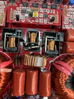
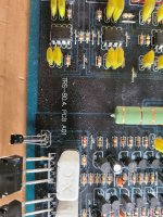
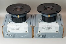
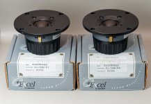
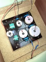
Celestion Ditton 66 crossover original green film caps - keep or replace?

Have read up on replacing the electrolytics when out of spec BUT.. does replacing the original green caps for the tweeter section result in a noticeable improvement with say Ansar Supersound or other new polys?

If in they're in spec, keep the greens or change?

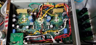
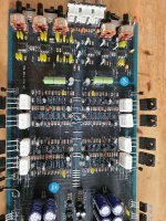
The boards were recapped about 5 years ago and as one can see, it's nearly all ALCAPS which is generally seen as a good thing I believe.
Any advice appreciated.

Attachments

  • IMG_1401 2 copy.jpg
    IMG_1401 2 copy.jpg
    715.3 KB · Views: 523

Crossover inductors - roll-yer-own

Hi all
I am needing to make some simple two-way crossovers for car 2-way component speakers, and am struggling to find the right inductors, so I am asking for advice about this, or suggestions about making some myself.

The speakers are Fli Integrator Comp 5 - a 5 inch single cone bass/mid plus a 1-inch tweeter. But they only came with one crossover. Initially I thought to simply duplicate this crossover to have a pair, but this crossover is basically just a 5.6uF non-pol cap in a box.

But - before I did this - a brief check with a crossover calculator had me questioning this 5.6uF cap choice by the manufacturer...
The drivers' resistance are - woofer - 3.4ohm and tweeter - 3.4ohm - so a 5.6uF cap in series with the tweeter gives a crossover of 8350Hz!
If this cap value was calculated on the basis of the tweeter being a nominal 4ohm, then the crossover would be 7100Hz (still too high).

(Apologies in advance - I am a newcomer to crossovers...)

Anyhow - basically I need to make crossovers for these two-way speakers. I can use online calculators to arrive at component specs, and source the caps and 5-10w resistors for l-pad attenuation of the tweeters if necessary - but I have questions about the inductors including what types, and what wire thickness for a tweeter vs woofer inductor, availability, and whether to make my own.

But first - what is the recommended crossover frequency for these, without exposing the tweeter to lower frequencies that might damage it?

For 1st order Butterworth, this looks reasonable...
Tweeter 3.4ohm, Woofer 3.4ohm
Tweeter - C1 = ~10uF,
Woofer - L1 = ~0.12mH
Crossover = ~4635Hz

Or L-Riley 2nd order:
C1, C2 = ~4.7uF
L1, L2 = ~0.22mH
Crossover = ~5000Hz

And if tweeter attenuation if needed, 1R & 10R resistor pairing = 2.89dB attenuation, and 1R5 & 4R7 = 4.91dB - but first I need to install the speakers to see whether this is necessary.

As I said, the only thing that's stopping me here is the inductors...
Specific questions would be...
With inductors, what would be the typical copper wire thickness for a tweeter or woofer inductor? The woofer/mid I have says '75W RMS' on it, and the tweeter - nothing written on it but it will be much lower than this - probably less than 10watts? So no doubt, this could be a much thinner-gauge inductor.
And - is it always air-core for crossovers - not ferrite core - whether it's the high pass or low pass inductor?

If I know the gauge of enamelled wire to buy, what's to stop me rolling my own? What sort of lengths would I be looking at?

I have a component tester which does inductors.

At the moment, I would be happy to just do the 1st-order crossover to get it up-and-running, and if that doesn't sound right, try a L-R 2nd later. Therefore I'd need 2 x 0.12mH inductors. Though I understand that the L-R 2nd-order might give more protection, given that car speakers sometimes get pushed to distortion to compete with road noise etc.

Any suggestions or thoughts greatly appreciated.

Thanks

Why One can oftten appreciate more the sound of his stupid planar TV sound than bigger loudspeaker ?

OK. It is a lot about voices playback I often found more enjoyable and coherent despite my TV is a basic planar than fires its sound from the back towards the (sounding) front wall... with most of the time a space gap of few inches ?

Are there experiences of stereo loudspeakers that fire toward the center of a front wall ? How the guys in TV devices designers plants design that to be good enough ? 100 hz to 6 k hz from a single FR and you're ok ?

I'd like the playback experience of my hifi was as confortable as my TV for voices coherency ! And not sure my hifi is crap for whose whom would ask...

Parasound HCA-1200II different output transistors variants???

Hello everyone, i come across Parasound HCA-1200II amp,really like it but find out it has Toshiba 2SA1553 and 2SC4029 output transistors. In service manual, only one i have found and get from Parasound service (they said they don't know anything about this old amp..), output transistors are SanKen 2SA1386 and 2SC3519.
And BIG QUESTION, is there two variations of this amplifer in production or someone messed it up????
John Curl, everyone...help

BGW 250 Professional Power Amplifiers as home audio

I was offered a nice BGW 250D power amp for almost nothing, there is not much information about the amp other than is a pro type of amp.

What do you guys make of the 250D ? any good ?

https://www.hifiengine.com/manual_library/bgw/250.shtml

http://lcweb2.loc.gov/master/mbrs/r... Series Prof. Power Amplifiers (brochure).pdf
  • Like
Reactions: geraldfryjr

Which horns are these ZXPC clones based on?

Does anyone know which horns these ZXPC horns are based on/clones of?
There's very little information on them, so I'm trying to gather some.

Here's the horns I'm wondering about:

https://www.ebay.com/itm/333338419879
https://www.ebay.com/itm/331477247778
https://www.ebay.com/itm/331676072699
https://www.ebay.com/itm/231420420855
  • Like
Reactions: behappybevegan

Transformer Input Type 45 Amplifier

Over the last few years I have been collecting transformers from Sony TC-500a tape decks. I recently saw a very simple schematic for a transformer input power amplifier and wondered if there was a reason I would not want to create something like this using TC500a OPT for both the input and output transformers. With a 5k primary and 8 Ohm secondary, the voltage gain of 25 seemed to be approximately right, especially if driven using a balanced input. I have a matched pair of 45 tubes for the outputs. My knowledge of tube amp design is very close to zero, but it appears this design does not include NFB. Would there be a way to incorporate it? Or at least provide for the option. Or would it not be needed?
I would appreciate any suggestions.

Thanks.

Supercharger_amplifier.png

DC heater ripple

On my obligatory lunch break, wondering if an idea could work...

I measured the ripple on the filament dc to the 300b's and measured about 550mv..

have some 1 ohm dropping resistors about to go in to reduce the 6.2 to 5v so will need to recheck but point is i have a little voltage to play with if needed...

if the 5v windings in the ps were out of phase with each other by 180, and converted dc combined, in theory shouldn't the ripple cancel itself leaving a smooth(r) 10v ?
If so, could a voltage divider be used to supply a now more ripple free 5v to each of the heaters??
First chance I get i plan to ac couple both heaters on the o-scope and verify the phase... i already know there's no center tap for the heater winding and dont share a common natural so to speak, imagine that simply revesing the ac conn to the bridge rectifier on one side could work..

Curious what more experienced minds think of all this...

FS: Troels Gravesen's Nomex 164 MkII, Crossover Kit

For sale a set of 2 assembled crossover for Troels Gravesen's Nomex 164 mkII speakers. I have the port tubes also, but no drivers.
Link to his built NOMEX-mkII

I decided to stop the build, is to difficult for me to make the cabinets.
I paid $450 USD plus shipping and taxes for the version with Alumen Z-caps
You can have them for $300 plus shipping.

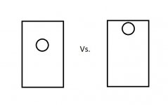
Driver at top or down 1/3 in 1:1.618 big sealed ?

I am a firm believer in 1 x 1.618 ratios………….

So let’s make a box, say 33” tall x 20” wide x 13” deep………….

Has anyone measured or heard a difference when the driver is roughly 1/3 from the top dimension versus at the top ?

On more of a pencil, or mltl design, absolutely, anything column-like, where 2 dimensions are fairly close, then the 3rd dimension is 2-3 (or more) times larger, pipe-ish basically, I can see offsetting the driver, even seen the measurements.

My thoughts are it wouldn’t matter much on this big sealed 1 x 1.618 x 2.62 ratio box.

Whatcha think ?

Attachments

  • driver mid or top of baffle.jpg
    driver mid or top of baffle.jpg
    10.3 KB · Views: 90

Firewire from pc or laptop to Pioneer VSA AX10i

hi all could anyone tell me would it be possible to send a FireWire signal from a pc to my pioneer vsa ax10i ilink inputs thus using it as a multichannel power amp with remote control of volume for a 3way active speaker build using the pc for crossover and eq etc ? also why are there 2 ilink or FireWire ports on the pioneer ? many thanks James

Anybody know what sort of prices I should be asking for this lot

I’ve just inherited some Sugden hifi, which I will have to put up for sale as I already have my own system Which I’m happy with.
It’s all working and pretty much in mint condition.

thanks Lee.

Attachments

  • 71CE0A53-B9FC-433E-B688-A0AA24A0F065.jpeg
    71CE0A53-B9FC-433E-B688-A0AA24A0F065.jpeg
    445 KB · Views: 200
  • ED9349EF-05D4-41ED-8FBE-BA27AD61D1A8.jpeg
    ED9349EF-05D4-41ED-8FBE-BA27AD61D1A8.jpeg
    373.1 KB · Views: 191

Ideas to help servicing ?

My ms-300 B was certainly not designed for servicing..
Along the very back there are 12 wires (In between the 50w cathode resistors) that need to be soldered to standoffs and they are within 10mm (or so) of each other.
This is always an exercise not unlike the game operation, and instead of the buzzer, you get a puff of smoke!

None of the other connections offer too much trouble, but I literally hate working on this amp because of those 12..

I was thinking another daughter board across the back that's much wider giving better access and raising the connection points to gain better access...
or may be as silly as it sounds, 2 6 pin connectors (1 for low voltage and one for high voltage) ??

Does anyone have any tricks or methods that can eliminate the problem all together (Besides the obvious!) ?

Attachments

  • Spaghetti.jpg
    Spaghetti.jpg
    433.6 KB · Views: 96

For Sale Beresford 7520SE Caiman Dac

Selling my Beresford Caiman 7520Se dac. This is the upgraded version of the 7520 with better dac chip, dual opamps and swappable as well as other improvements. Its in near mint condition and will come with stock opamps and DC power supply (aftermarket)

Trades entertained as well. I also have a Khadas toneboard listed as well as a Icepower PCB the 50asx2

asking 140 shipped lower 48 USA only. Paypal only.
IMG_7605.JPG
IMG_7606.jpg

AD1 replacement !

How can I replace the tube AD1, which tube? is very close, Maybe a pair of lamps in parallel can be similar? Does anyone have information?
Maybe there is a diagram - how to replace? I read a very long time, someone used two lamps in parallel 4p1l +4p1l

Attachments

  • Снимок экрана 2023-02-09 в 21.40.46.png
    Снимок экрана 2023-02-09 в 21.40.46.png
    1.1 MB · Views: 203
  • Снимок экрана 2023-02-10 в 17.39.25.png
    Снимок экрана 2023-02-10 в 17.39.25.png
    203.8 KB · Views: 189

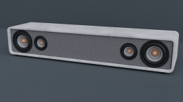
Looking for pointers to power my drivers & soundbar design critique

I'm completely new the DIY audio scene, however I would still like to make a DIY soundbar for my desktop setup. So I'm looking for pointers to learn to, or recommendations on how to power my current driver choices and all the relevant wiring.

I would ideally like a left and right channel from this soundbar for stereo output, along with a hdmi and aux input. The current drivers I am looking at are the:
Dayton audio DSA115-8 4" Woofer x 2 & Morel KT-1 1-1/8" Tweeter x 2

If these drivers are a poor match up, please inform me and would love other known and tested combinations of drivers in order to shrink the vertical size of my current soundbar design.
For the design I have currently it is a 800mm long x 140mm tall x 180mm deep concrete box with a wall thickness of 20mm with a face and back plate made of 5mm thick aluminium sheet metal. If this design allows for a top mounted or maybe even a bottom mounted sub woofer on the soundbar please let me know, and if that's stupid let me know that too.

Would love the help educating myself and all advice and suggestions would be awesome to get this project moving along.
Attached is a render of the current design for reference.

Attachments

  • untitled.png
    untitled.png
    1.2 MB · Views: 90

Price/quality speaker for beginner DIYer and to hifi

Hello guys,

I've finally convinced my friend to buy a hifi system and stop listening music with the inbuilt speaker of his computer. I've been into hifi for a couples of years now, so it's my job to find him a hifi-system. I'm personally a 19 year old student, and I'm honestly getting tired of the high prices of new speakers and the speculation on the prices of secondhand 'vintage speaker'. That's why I want to start building my own audio gear (I already started simple with a ACA amp) and it's the perfect occasion to start my journey into speaker building. I already informed myself with a lot of reading, so I'm no pro but not a noob either.

So here are my condition for the build;
  • about 250euros for a stereo set of speaker (2 or 3 way)
  • it's a pretty small room, like 4x4m (yes I know is a square, shame on him)
  • My friend isn't a critical listener, so a fun speaker to listen to (so a bit of boomy bass isn't that bad)
  • not too complicated, it's my first build
  • parts that are not too hard to find in Europe (Belgium more specifically)

So if you guys have some ideas or projects you would like to share to help me. It would be greatly appreciated.

I already thank you guys for the help,

Jules

Q: QUAD 405-1 secondary fuses and Speaker terminal removal

I have a couple of questions about my Quad 405-1 that I need help with.

IMG_4350.png


1. What are the values and types of fuses to be placed in those holders in the photo above? These fuses are inline with the secondary output of the transformer, just ahead of the full wave rectifier. The original are BS2950A 5A fast blow. I have scoured 405 documentation but none of it mentions these fuses or their specs.

2. How do I remove the speaker terminals and the clamp circuit in the photo above? There is no obvious way by examining the amp and I don't see any instructions at sites like Dada Electronics and Keith Snook.

Thanks for any help.

HELP, my tube amp is leaking voltage. Total newbie-desperate.

Hello all and thank you for accepting me into the group. I have not done any DIY amp work but willing to learn and very desperate at this point.
I own a 12-year-old Cayin A 88T integrated amplifier which I bias regularly. The last time I tried to bias the tubes I decided to clean the tube sockets with a 3M electronic quick-drying contact cleaner. I waited an hour before opening the amp to ensure it was truly dry.
I opened the amp, turned the biasing pot to the minimum, and turned on the power. When I checked the initial reading on the multimeter 3 tubes were at 0 and 1 had a 1400 reading in the multimeter. I shut it down immediately and waited 5 hours to check again. Same result but now the other tube on the same left side was reading 200 while the whole right side was still 0. Can someone please just give me an idea of what to check, replace, buy?
Thank you so much.

Attachments

  • IMG_4910.jpg
    IMG_4910.jpg
    675.9 KB · Views: 133
  • IMG_4915.jpg
    IMG_4915.jpg
    406.7 KB · Views: 150

Variac transformers SUNTEK 0-300 Volt

The accuracy of the input voltage for your audio equipment can simply be set using a variac transformer. They are on 2,4,8,12,20, etc. ampere. How to choose the right one. The calculation is as follows: let's say your equipment is 500 watts and you are going to use it at a voltage of 100 volts. The choice of the correct variac model is determined by the current consumed. We divide the power by the voltage, we get the current, in our case it is 5A. Thus, the nearest model variak 8A will be the solution.
Latr2.png

For Sale Sony VFET Amp - 2SJ18

SOLD

Too many amps already with me in the US, so I need to dispose off the Sony VFET amp built using 2SJ18 transistors from Pras that I got in 2021. The amp boards are from the diyaudiostore kit. Scourge input stage board kit and the output stage is the revision 3 kit from the store and it also has the psu filter board along with the Meanwell 36v adapter.

Not sure how much to quote, offers are welcome. One of my best amps but after my SissySIT this has gone to the
Please PM me with your offers and this is a very heavy cabinet so shipping within US but I would prefer local 60564, IL pickup or nearby drop offs.

Thanks

1675311503514.jpeg


1675311520285.jpeg


1675311486214.jpeg
  • Like
Reactions: tiverson

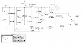
6SN7 with KT88 modification to schematic

My first thread here, hopefully some members could direct me to the right place if this has already been discussed. I would take the following schematic and run the power tubes with KT88 and possibly a tube rectifier. I couldn't find any schematic available for 6SN7 paired with KT88. This was the closest thing I could find on one of my books. Any suggestions or possibly direct me to the right area of research and discussion for this newb. to read up on? Or anything t take note on? Thanks in advance.

Attachments

  • 20230207_134240.jpg
    20230207_134240.jpg
    350.9 KB · Views: 500
  • 20230207_134456.jpg
    20230207_134456.jpg
    292.5 KB · Views: 425

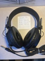
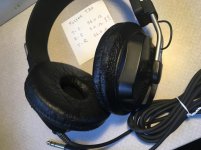
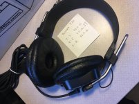
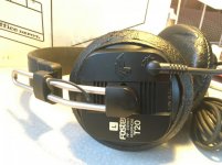
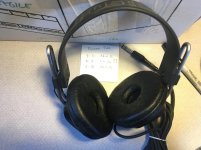
For Sale: Fostex T20 headphones, one driver out, $39 and FREE USA shipping

For sale: Used Fostex T20 headphones in clean and fine cosmetic condition. Earpads are still nice and spongy, and it only really has slight wear on one pad (see pics).
One driver is out and measures only 3 Ohms. It's not just the locking plug.

In 1999 one side stopped playing, and since then I've been meaning to repair them. But now it's someone else's turn with them!

$39 and free USA shipping

Attachments

  • IMG_1931.jpg
    IMG_1931.jpg
    103.3 KB · Views: 205
  • IMG_1932.jpg
    IMG_1932.jpg
    105.8 KB · Views: 210
  • IMG_1933.jpg
    IMG_1933.jpg
    128.2 KB · Views: 215
  • IMG_1934.jpg
    IMG_1934.jpg
    108.5 KB · Views: 221
  • IMG_1935.jpg
    IMG_1935.jpg
    124.7 KB · Views: 214

LM3886 intermittent channel static / cut out

On my LM3886 amp, which was pre-assembled, there is intermittent static which sometimes results in the entire channel dropping out. It is not isolated to left or right, and seems random as to which channel will make noise or fail. What seems to "fix" it is turning the amp off and on again, and then it will work properly until I turn it off again. Sometimes I have to turn it on and off several times before it works properly.

My first guess was that there was an issue with the volume pot, so I cleaned it with some deoxit and that seemed to help but it did not eliminate the issue. I did replace the volume pot with a linear attenuator (awesome upgrade, sounds so much better and I did not expect that) BUT the channel static/cut-out issue persists. So I can say for sure the pot was part of the problem, but before I start replacing other parts I was hoping that someone else could suggest what this could be:

1) The power switch seems like the next logical thing to replace but it's a small switch and it appears to be wired downstream from the mains, meaning: Mains > Fuse > Transformer > Switch (on secondaries) rather than Mains > Fuse > Switch > Transformer Primary. If I had built the amp myself I would have placed the switch between the fused mains and transformer primary...and if I have to switch the switch, I'll likely rewire it to be that way unless there's a reason not to.

2) The volume pre-amp board, where the attenuator connects, also has two opamps and is powered by a secondary low voltage winding off of the transformer. Is the preamp board itself bad? Any way to test this without replacing it?

3) Something else? What?

Limited Edition Fostex FE108SS-HP

https://sagamiaudio.co.jp/fostex-fe108ss-hp/
Anyone here get their hands on this driver?

fostex-fe108sshp-3.jpg

Impedance 8Ω
・ Reproduction frequency Band FO-28kHz
・ Output sound pressure level 88dB / W (1m)
・ FO: 81Hz
・ MO: 3.2g
・ Q0: 0.39
・ Input 15W (Mus.)
・ Total weight 1830g
・ Baffle opening: φ102mm

Pair standard price: 50,000 Yen (excluding tax)

Product details (manufacturer page)

fe108ss-hp (sold as a set of 2)

Category A (Our company or manufacturer inventory)

¥ 50,000 ¥ 50,000 (excluding tax)

( ¥ 55,000 including tax )

quantity


IDK and have yet to ask if Madisound will offer this driver.

  • Poll Poll
Do you borrow money to buy hifi or parts?

Do you borrow money to buy hifi or parts?

  • yes i do

    Votes: 3 4.7%
  • no i do not

    Votes: 61 95.3%

prices on hi end gear keeps going up, with prices that not all people can afford, so do you loan money to buy gear?

(this is my first try to do a poll and i really do not know if i have done this right, pardon me if this goes unwell.)

ChatGPT is a FFT denier

I asked: "can FFT accurately analyze transient non linear signals? "

ChatGPT answered: "
Fast Fourier Transform (FFT) is a technique that is commonly used to analyze and understand the frequency content of signals. In general, FFT can accurately analyze periodic or stationary signals, which have a constant frequency content over time. However, when applied to transient or nonlinear signals, FFT may not provide accurate results.

Transient signals are signals that change rapidly over a short period of time and they can be aperiodic or non-stationary, meaning that the frequency content of the signal is not constant over time. These types of signals have a time-varying frequency content, which makes them challenging to analyze with FFT.

Nonlinear signals are signals that have a non-linear relationship between the input and output, and they may produce harmonics and intermodulation products (IMD) that are not present in the input signal. These signals also have a time-varying frequency content, and their frequency content is not constant over time.

FFT assumes that the signal is periodic and linear, so it may not accurately represent the frequency content of transient or nonlinear signals. There are different techniques that can be used to analyze transient or nonlinear signals such as wavelet transform, Hilbert-Huang transform, and Empirical Mode Decomposition which can provide better results than FFT in certain scenarios.

In summary, FFT is well suited for analyzing periodic or stationary signals, but it may not provide accurate results when applied to transient or nonlinear signals. Other techniques such as wavelet transform, Hilbert-Huang transform, and Empirical Mode Decomposition can be used to analyze transient or nonlinear signals."


Me: "Does musical instruments like drums and bass guitar mainly create periodic or stationary signals, which have a constant frequency content over time or do they create transient and non linear signals?"

ChatGPT: "
Musical instruments like drums and bass guitar can create both periodic and transient signals, depending on how they are played.

Drums, for example, typically produce transient signals when they are struck, as the impact of the drumstick on the drumhead creates a sharp, sudden pressure change that decays rapidly over time. The sound of the drum may also contain some harmonic content, due to the non-linearity of the drumhead.

Bass guitar, on the other hand, can produce both periodic and transient signals. When playing a sustained note, the sound produced by the bass guitar is likely to be periodic and have a relatively constant frequency content over time. However, when playing percussive or staccato notes, the sound produced by the bass guitar may be more transient in nature.

In general, it can be said that most musical instruments produce both periodic and transient signals to some degree, depending on how they are played. The periodic or stationary signals are the fundamental frequency and its harmonics, while the transient signals are usually the result of the attack and decay of the sound. The non-linearity of the instrument and the way it is played can also produce harmonics that were not present in the input signal, and therefore the signal is not linear.

In summary, musical instruments like drums and bass guitar can create both periodic and transient signals, depending on how they are played. The periodic or stationary signals are the fundamental frequency and its harmonics, while the transient signals are usually the result of the attack and decay of the sound, and non-linearity can also produce harmonics that were not present in the input signal."

Me: "is FFT suitable to analyze the sound generated by drums and bass guitar?

ChatGPT: "
Fast Fourier Transform (FFT) is a technique that is commonly used to analyze and understand the frequency content of signals, and it can be used to analyze the sound generated by drums and bass guitar. However, the results obtained from FFT may not be entirely accurate for transient signals or for signals that have a non-linear relationship between the input and output.

For example, when analyzing the sound of a drum, FFT can be used to determine the fundamental frequency and the harmonic content of the sound, but it may not provide an accurate representation of the transient impact of the drumstick on the drumhead. In this case, other techniques such as the wavelet transform or the Hilbert-Huang transform may be more suitable to analyze the transient nature of the sound.

When analyzing the sound of a bass guitar, FFT can be used to determine the fundamental frequency and the harmonic content of the sound, especially when playing sustained notes. However, when playing percussive or staccato notes, the transient nature of the sound may be more dominant and FFT may not provide an accurate representation of the sound.

In general, FFT can be a useful tool for analyzing the frequency content of a sound, but it may not be entirely suitable for analyzing transient or non-linear signals. In these cases, other techniques such as the wavelet transform or the Hilbert-Huang transform may be more appropriate. Additionally, the results obtained from FFT should be interpreted with caution, especially when analyzing transient or non-linear signals, as they may not be entirely accurate."


ChatGPT's assertion that other techniques, beyond FFT, may be more suitable for analyzing transient or non-linear signals in music, challenges the notion that FFT is the ultimate and only means of signal analysis, and suggests a departure from the simplified understanding that music can be reduced solely to combinations of sine waves. 😉

As in the name of this forum htread.... ChatGPT is a simple and dumb FFT-denier....
  • Like
Reactions: mterbekke

PC to Stereo System Interface

I regularly watch and listen to music posted on youtube through my stereo setup. I currently use the "headphone" output of the PC with a 1/8" stereo to dual RCA adapter and into the AUX connection of my stereo preamp which feeds my power amp and speakers. Can someone recommend a simple interface, 2-channels only, that would provide better sound than what is coming out of the headphone jack? I would like to keep the cost under $150.00. Thanks
Driverack PA setup question

I am experimenting with a Driverack PA (not PA2) with a home stereo. I'm using the wizard to set up the EQ mainly to learn some of the things it can and cannot do. I hope to get a much better DSP setup later and use it with better analysis software. But for now, it is interesting to watch this wizard work (this one uses pink noise and sets a 30-band equalizer).
I have found that the wizard gives a good result but in addition I have to set one or two PEQ filters manually to get what I like.

My question s concerns the output level. The output level is much higher than the input level (I would expect this as I used a flat response target and some low frequency boost is required). But sometimes the driverack output is driven to distortion. I think this could be remedied by using the setup wizard to "tell" the driverack that the gain control on my amplifier is set higher than indicated at present. I skipped this step during my initial setup, thinking I could get back to it later. But I can't find a way to use just that part of the wizard, keep my EQ settings, and then stop and store a new setup file. The driverack insists on completing all subsequent steps including the pink noise EQ, etc. Does anyone know how to change just the signal level part of the stored settings?

Thanks,
Tom

Carver MXR-130 Bias help!

Hello, i’m sorry to be long winded, but I’d like to give detail on my situation. I’m looking for some direction in regards to a Carver MXR-130 receiver I picked up on eBay. I bought it as is and received it in very nice cosmetic condition. I am a diy’er and didn’t want to just power it up not knowing what I may find. I opened up the top of the unit and visually inspected. Other than some really hacked solder joints, I didn’t see anything burned up so I plugged it into a dim bulb tester and powered it up. Nothing smoked immediatel. After it ran for about 10 minutes or so, I removed it from the dim bulb and went to straight power. I connected up a source and some test speakers. It works, and it can play pretty loud. I found the service manual online and found the alignment process and some of the known issues for failure. I addressed a lot of the solder joints that looked shotty, replaced the output relays along with beefing up some various resistors. The voltage adjustment is exactly at 61v on d626 (cathode to chassis.) The idling voltage is where I’m having the issue. The Service Manual calls for 5mv on test points 602 & 601 for the left channel and test points 603 & 604 on the right channel. The bias is only .2mv on the left channel and .3mv on the right. I tried to adjust SVR 501 for the left & SVR 502 for the right channel. The highest I can bring the bias is up to .6mv on the right channel and .4mv on the right. If anyone is familiar with these units, can you please walk me through the troubleshooting steps. It’s most likely that whatever is the issue on the one channel is probably the same issue on the other. Any help would be greatly appreciated. Thank you in advance, Joe

Attachments

  • 8AD12818-7467-41EE-A022-DCCFE3063619.jpeg
    8AD12818-7467-41EE-A022-DCCFE3063619.jpeg
    93 KB · Views: 205
  • EF06BA9E-F720-491F-8AB3-85817A3EBAAD.jpeg
    EF06BA9E-F720-491F-8AB3-85817A3EBAAD.jpeg
    87 KB · Views: 190

synchronising two USB-I2S devices over master clocks

hello, if we want to combine two usb asynchronous dac's in alsa to use as one device. The requirement is that audio word clocks should be synchronised. That is understandable. But what if i don't have possibility to synchronise word clock , but master clock instead?
what will happen if i plug these two usb devices sharing the same master clock. Word clocks will be randomly off everytime i plug them to pc? is that correct?

Question about bridged mono operation

Got a Rotel 970BX which has been serviceable. Been using it in bridged mono mode. Recently noticed a performance degradation and pretty sure based on some bench measurements (no voltage drop across the emitter resistors) the right channel NPN output pair is dead. Switching to stereo operation and no right channel seems to confirm my initial diagnosis.

In looking closer I noticed that the left channel has the original design 2SD1047/2SB817 output devices but the right channel has NJW3281G/NJW1302G output transistors, which according to my old notes, I installed several years ago when I first acquired the amp.

The theory part of my question goes like this: when running this (AB push/pull??) topology in bridged mono how important is it for the devices on one channel to be from the same product family (2SD1047/2SB817) versus a different family (NJW3281G/NJW1302G)?

The practical part of my question goes like this: If in fact the 2 right channel NPNs are blown is it better (does it matter) if I replace them with the 2SD devices (to match all the devices on the left channel) or with the NJW devices to match the pull side of the right channel).

First cab design. Bandpass??

Hi All
I have designed my first speaker using horn response. I guess its a bandpass which is intended to be used as a kick.

My question is: at s2 its quite a small area, this is matched as its supposed to be in my horn response simulation but i wonder if such a compressed area will result in other unwanted effects such as distortion etc. Furthermore would this be considered as the compression ratio???
I am no expert so any constructive critisism is appreciated.
If anyone has any suggestions to how i could improve this design please let me know.


1675959430449.png
1675959582344.png
1675959631576.png
  • Like
Reactions: DorinD

LEBEN CS300F: 6CL6 drop-in replacement for JAN6197?

Our LEBEN CS300F integrated amplifier uses GE JAN6197 tubes in the output stage.

I've got hold of some RCA 6CL6 tubes in the hope that I can drop them in when the time comes.

Doing a quick double-check, I noticed some small differences between the two tubes.

On their respective datasheets, the main difference I have spotted is:
6CL6 has a much higher PLATE RESISTANCE specification.
[6CL6 ra=0.15megOhm versus 6197 ra=0.09megOhm]


My thinking is that because the LEBEN has been designed around the lower maximum plate resistance of the 6197, the 6CL6 should pose no problems - replacing the 6197 - in this regard.

One remaining outstanding question is:
Do the two tubes share the same level of Gain?
I have been unable to find this info.

Can I ask the more experienced members here to look these questions over and comment please? Appreciated.

[Photo below shows original GE JAN6197 together with the 17EW8 HIFI preamp tube...]
19.jpg

Need help decoding crossover

So I would like to replicate the crossover shown below, but having a hard time understanding it.
Partly because I'm a newbie at this and partly because of all the glue!
I think left inputs are negative. Looks to me like a second order filter, and I know there is supposed to be a notch filter for the HF.
And possibly an RC filter for the LF? Speaker has biwiring, so two sets of inputs. Lower half is LF circuit, and upper half is HF circuit.
If someone is able to make a schematic from this, that would be fantastic 🙂 Not looking for component values.

crossover.png


EDIT; here's another pic I found of the same crossover that shows the component in glue better.

1675759265444.png


Conserning the component with a questionmark (hidden in glue) in the first pic, it looks like this (and the one between the two bottom inductors) is an Ohmite wirewound resistor;

1675759304992.png

FS: Tomcat Audio Preamp

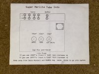
This is the Tomcat Audio Super Merlita Preamp
Super quiet and clean with point to point
Wiring. Hammond Transformer
You can use 12au7, 12ax7 or 12at7 to your taste very flexible preamp with clean beautiful soundstage.
The unit is like brand new with roughly only 20 hours on it.
Asking $700

Attachments

  • BFA599F7-A5F1-4462-8F0D-AF0FE93CEF06.jpeg
    BFA599F7-A5F1-4462-8F0D-AF0FE93CEF06.jpeg
    282.4 KB · Views: 159
  • 53D8CFED-8256-45FC-8EC6-F1E3BA89BA11.jpeg
    53D8CFED-8256-45FC-8EC6-F1E3BA89BA11.jpeg
    290.8 KB · Views: 142
  • 367949EF-7355-4593-8B09-E4C2674B1B95.jpeg
    367949EF-7355-4593-8B09-E4C2674B1B95.jpeg
    322 KB · Views: 139
  • 56702089-30AF-47E7-80A3-5CAA03D4375A.jpeg
    56702089-30AF-47E7-80A3-5CAA03D4375A.jpeg
    468.6 KB · Views: 146

Mackie HD1531 Repair Help

Hi everyone ! I'm trying to fix a mackie hd1531 amplifier module ! the problem is that I have no audio output on the mids and trebles! after checking the output mosfets I noticed that with the oscilloscope I don't have the clock signal for the 2 IRS20957s! I added the circuit diagram ! If you have any suggestions I'd be happy

Attachments

Physical format: CD's still outselling vinyl

John Darko sheds a little light on the weird mainstream media in his new video.
Login to view embedded media Yes, those new UHQRs and Chad Kassem and Speaker's Corner and MoFi 200g are probably part of reason why vinyl sales ($$) are so high.

USA RIAA sales, 2021:
RIAA EoY 2021 report

https://www.riaa.com/wp-content/uploads/2022/03/2021-Year-End-Music-Industry-Revenue-Report.pdf

Loudspeaker/Amplifier Damping Study using Impulse at the Amp Input

Various methods can be used to check the Damping Factor of a bare amplifier,
Here is a simple variation of that, this one looks at the amp with the loudspeaker it will be used with.
It needs a scope that can be triggered for a single shot. And a 1.5V Cell.

The test simulation is setup here in Electronic Workbench. The circuit is common.
Several switches labelled as keys on the keyboard allow a number of variations in the amp.
A standard R load or a choice of two loudspeaker simulators can be selected.

The first pass is on a speaker simulator by Ken Kantor. The amp is connected as an SE pentode.
The scope is set to trigger once when it sees a preset voltage change.
Over the next while I'll add to this. 🙂

Attachments

  • img20221231_13154450 Impulse Test A2.jpg
    img20221231_13154450 Impulse Test A2.jpg
    189.1 KB · Views: 197
  • Like
Reactions: bondini

cooling fan for tubes

So I'm wondering if adding a fan is beneficial. I have Acoustat X Direct Drive Servo mono otl amps. They are always on but on standby til they receive signal. It seems sq peaks after about 5 songs and then drops off but very slightly, I'm actually not quite sure. Sound is a bit less crisp/up front sort of. Maybe it's just in my head? Maybe line voltage? It's 122v here.

recommended pre and power tubes for 8200

curious if you have other suggestions worth trying for my elekit 8200

right now i have sylvania 5814s with the KT66; so far i must say that the

goldlion 12au7 and kt66 is my favorite combo, good base and nice warm sound

drivers
gold lion 12AU7
philips holland ecc82
ge holland ecc82
tungsol 6189
baldwin clear top 12AU7
Sylvania JAN 5963
1951 RCA 12AU7 black plate

powertubes
gold lion KT66 KT77 and KT88
tungsol EL84s
tungsol 7581
tungsol 6L6GCSTRs
electro harmonix 6L6GC


primary music (80% of time ) is electronic - acid jazz, house, deep house, trance, along with classical music (piano concertos mostly), vocal jazz, phish, the dead and along with many other types of music (20% of time )depending on my mood!

for headphones i have grado 80SR80e which are ok, but since i think there may be better out there just picked up some sennheiser 6xx and akg7xx to try out

is there anything im missing?

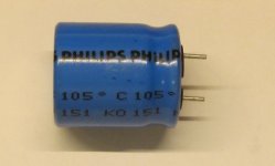
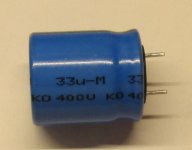
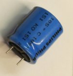
Philips 33uF 400V cap age?

Hi all,

I bought a cheap Chinese amp kit that has been around for a long time. About 4 years ago, it was advertised with "used tested good" Philips caps in the power supply. Who knows what that meant. Today I got one with a 33uF 400V capacitor made by Philips. It's supposed to be a 22uF (C3 on schematic).

Does anyone have any idea how old this cap might be and whether I should just spend a few bucks and replace it before I build the kit? Schematic and cap photos attached.

Attachments

  • cap 1.JPG
    cap 1.JPG
    106.6 KB · Views: 139
  • cap 2.JPG
    cap 2.JPG
    81.1 KB · Views: 142
  • cap 3.JPG
    cap 3.JPG
    70.8 KB · Views: 163
  • 5.pdf
    5.pdf
    443.9 KB · Views: 165

Jantzen Silver Z Cap vs Alumen Z Cap

Hi,

About 6 years ago, I built Troels Gravesen Audio Technology Classic 3 Way. At the time, the speaker kit used a total of 10 (2 x 5) Jantzen Silver S Caps. I've noticed that now the kit used Alumen Z Caps.

I have always found my hifi system slightly on the bright side, but I have read that the Alumen Z Caps are less bright and sound more natural....I was just curious if anyone here has any experience using them and whether given the high cost of the caps if changing them would bring a significant change to the sound or if they will merely fine-tune the sound.

Willsenton R8 heavy distortion in triode mode

Hello:

I own an out of warranty Willsonton R8 tube amplifier using KT88 tubes and everything is stock. This amp has a triode and ultralinear mode. I'm connecting it to Polkaudio RTi A7 speakers as well as some Klipsch RP-600.

Very happy with the sound but the other day I cranked up the volume to see what else it can do and the result was not pleasant. In triode mode, when I go past 10 o'clock on the volume scale it starts to distort in the louder sections, or the peaks. The distortion comes in the form of loud pops or crackling, kinda like the sound that tends to blow speakers, like a dirty pot at high volumes. This happens in both channels equally.

When I switch to ultraliner mode everything sounds clean, no popping or crackling. Went all the way to 12 o'clock in this mode and continues to be clean.

I've contacted Willsenton support and they responded quickly asking what speakers I have. Nothing past that so I was wondering if the knowledgeable people on this forum have any ideas what might be the cause. I sure hope it's not the output tubes, or God forbid, the output transformers. I'm not sure if I ever tried to go that loud before so I have no idea is this issue was always there or developed over time. One thing is for sure, both channels start to pop at the same point equally bad.

Can anybody that has this amp with stock tubes KT88 tried to crank the volume in triode mode and see if they experience the same thing?

I've attached a schematic for your review. I'm somewhat knowledgeable and I can take measurements if needed. Not sure how far Willsenton support is willing to go so I'm on my own.

Thanks

Attachments

  • Schematic3.png
    Schematic3.png
    16.4 KB · Views: 1,631

Swap 30 AWG kynar wire blue for green

I have a 1000 foot roll of 30 AWG BLUE kynar/wire-wrapping wire; more than I will ever use. I am working on a project of adding modifications to a PCB that is colored GREEN. I know it may sound silly, but I'd really like my mod to be as unobtrusive as possible; thus it would look nice with the green wire. But I really don't want to spend the $$$ on another 1000 foot roll. Anybody out there want to swap their green wire for my blue? I don't need all that much; 30 feet would be enough. Wanna trade??

A 200V PS for use with TV Horizontal Sweep Tubes

A 200V PS for use with TV Horizontal Sweep Tubes

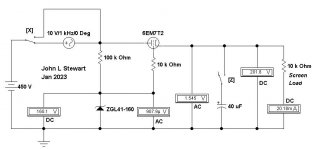
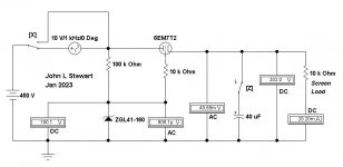
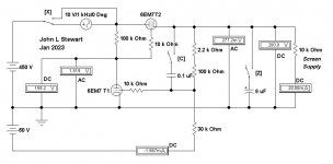
Surfing around on DIY we see quite a few requirements to supply the screen of this or that sweep tube. Here is my take on something that works reasonably well. And the circuit can form the starting point for others.

I selected a 6EM7 for this exploration, it can dissipate 11W. The H-K insulation is good for 200V allowing the heater to operate from the common 6.3VAC heater supply. And there is a high mu triode in the same bottle that can be used as an error amplifier. And it looks nice, important for those who are building their work of art.

The simple simulation without an error amp shows a very basic 200V G2 supply. With 450V B+ the drop of 250V supplying 20 mA results in dissipation of ~5W. This using a Zener as the reference, it could just as well use a VR tube.

The Sim has 10VAC interfering signal that can be switched in series with the 450V DC to fill in for ripple on the raw B+. The action of the 6EM7 T2 is to reduce this by its 1/mu. If the 6EM7 T2 were a perfect triode the resultant ripple at the output would be 1.85VAC. It isn’t. So AC from the PS ripple is 1.545V. Connecting a 40 microF cap across the output reduces the ripple to ~50 mV.

The regulation to load changes can be estimated by treating the output of the circuit as a cathode follower, ( rp + Rsupply ) / ( mu + 1 ). At 20 mA rp is not 750R as we see at the top of the data sheet. For the brave you can go to page 13 of the attached data. There you will find the required information, a rather steep curve. The triode model in the simulator used does not do well here!

The simple 200V supply works but will do much better with some gain applied to the error.

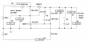
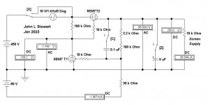
Using the 6EM7 T1 triode as the error amp requires a negative supply. This is something that is easily fixed by providing a simple, stable negative voltage, supplying just the reference. Several folks mentioned they had a PT with a 60v tap, so that is a convenient place to start. There are several ways to get the negative reference voltage. That is something to be looked at later.

Now the 60V reference is compared to a fraction of the output voltage, in this case simply

~ 30 / ( 30 + 102.2 ) ……………………or about 23%

When writing equations for Reg PS performance this fraction is often referred to as K. A large K is preferable, that could be achieved here with a 150V reference. Something to keep in mind.

With the error amp in the circuit the ripple on the output is reduced to ~1/4 Volt. By connecting a small cap from the 200V rail to the error amp grid the factor K becomes One. And the ripple at the output is further reduced. And finally an electrolytic across the output to supply any large surges of G2 current in amp it works with.

In the next exciting episode various ways to get a good negative reference without pain, suffering & agony!!

Attachments

  • Smple 200V Supply A.JPG
    Smple 200V Supply A.JPG
    25.1 KB · Views: 202
  • Smple 200V Supply B.JPG
    Smple 200V Supply B.JPG
    26.6 KB · Views: 196
  • Simple 200V Supply C.JPG
    Simple 200V Supply C.JPG
    35.1 KB · Views: 183
  • Simple 200V Supply D.JPG
    Simple 200V Supply D.JPG
    35.4 KB · Views: 178
  • Simple 200V Supply E.JPG
    Simple 200V Supply E.JPG
    34.8 KB · Views: 200
  • 6EM7 RCA w Errors.pdf
    6EM7 RCA w Errors.pdf
    574.7 KB · Views: 112
  • Like
Reactions: prairieboy

Zapco C2K 9.0XD

Hello all,

I've got a Zapco 9.0XD that powers up (green LED) for 5 seconds then when the volume light (yellow led) flashes, relay clicks in, then the protect led flashes then the #2 and #4 pre-clip leds illuminate and stay illuminated while the amp continues drawing excessive current as can be seen by the head lamp in series with B+.

This amp is supposed to idle at 3.8 amps so I placed a 10 amp fuse inline with B+ while removing the headlamp and it blew it as soon as the relay clicked.

Upon visual inspection nothing looks bad, except the 30 ohm 3 watt resistor R136 in the power supply looks discolored/burned, but still reads 29.87 ohms.

I am going to start removing the clips and testing FETs, Transistors and diodes, but if anybody is familiar with this one and could point me in the right direction of where to start troubleshooting I would greatly appreciate it.

Also, of course it would be great if someone had a schematic.

I have an email and phone number for Zapco and plan on contacting them Tuesday if no one has a schematic, but I am not sure how they are about releasing that info.

I can also supply pictures of more specific areas of the board.

Thanks.

Attachments

  • 20220702_142300.jpg
    20220702_142300.jpg
    338.3 KB · Views: 389

Audio Gods 4 channel amp in protect

Hi all,

I have the below amplifier in protection. I narrowed it down to a shorted transistor. there are no markings on the transistors. What can I use as replacements?

20230209_090551.jpg

Attachments

  • 20230209_090551.jpg
    20230209_090551.jpg
    839 KB · Views: 127
  • 20230209_090555.jpg
    20230209_090555.jpg
    742.5 KB · Views: 170
  • 20230209_090606.jpg
    20230209_090606.jpg
    664.5 KB · Views: 146
  • 20230209_090613.jpg
    20230209_090613.jpg
    466.8 KB · Views: 129
  • 20230209_090617.jpg
    20230209_090617.jpg
    682.8 KB · Views: 143

Ideal Driver for a 2.3 cubic foot cabinet

I recently acquired a sub cabinet that has 2.3 cubic feet if internal volume and was wondering what drivers would work the best in it. Currently it is set up sealed for a 10 inch driver with no amplifier. I have no problem moving to a 12 or 15 inch sub if that can utilize the space better or adding a port if needed.
I would like to get down to 25hz if possible. I have a few Dayton ST255-8 10 inch woofers sitting around but I don't feel that I can get low enough with them.
This will be used mostly for home theatre if that matters at all.
Thanks in advance,
budzos

Better transistors for class-A bias?

The Tangent Pimeta2 I mentioned in another thread uses several common TO-92 transistors for bias op-amps ( into Class A).

Tangent suggests:
Q1, small-signal PNP ( 2N3906 and the 2N5087 are known to work, as should the PN2907)

Q2, Q3L, Q3R, small-signal NPN: (possible: 2N3904, 2N5088, and PN2222.)

Any improvement possible by, say, upgrading these to Japanese, Zetex or other models by "better" manufs?

See:
https://tangentsoft.com/audio/pimeta2/
https://tangentsoft.com/audio/pimeta2/pguide.html

Preamp Circuit Advice

Attached is a schematic of a preamp selling in kit form on ebay from a well known Chinese store which many of you have probably seen, and which i was thinking of buying and upgrading.

I have a reasonable understanding of amplifiers and schematics and can build from scratch however my understanding of topology and theory/design of amps is very basic, is there anyone who can look at this circuit and give my some feedback on its design and how it might be improved.

It would pair with and Aleph J power amp.

Many thanks

s-l1600.jpg

Stereo to mono converter

I recently acquired this passive converter:

Single Stereo to Dual Mono Audio Converter Mono Out retains L/R Input Isolation
  • Input connectors: Stereo L/R RCA
  • Output connectors: 2 x Mono RCA
  • Utilizes independent 1:1 ratio dual audio transformers
  • Dimensions (L x W x H): 2 5/8" x 1 5/8" x 1 1/4", Gold plated connectors
  • Passive circuitry, no external power required
My intention had been to send the output to two separate 1950's era mono vaccum tube amps.

Attaching one device to one output channel works well. But when I plug both devices into the converter simultaneously the signal is barely audible.

Is that to be expected?

If so, I am struggling to imagine what the use case for sending two mono channels to a single device is. Something out of my range of experience, perhaps.

Screenshot_20230209_094454_Amazon Shopping.jpg
Projects by fanatics, for fanatics
Get answers and advice for everyone wanting to learn the art of audio.
Join the Community
507,619
Members
7,880,131
Messages

Filter

Forum Statistics

Threads
405,871
Messages
7,880,131
Members
507,619
Latest member
Yahweh1x