Hi All
Like many others on here i have some armstrong audio love to rekindle, i remember as a child my uncle playing his 625 receiver through some kef speakers, at that time it was so lovely to hear and look at, this was my first introduction to hifi.
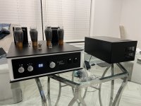
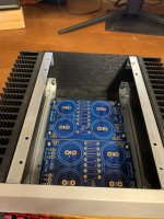
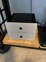
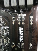
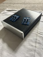
Even today the looks of these amplifiers are brilliant! So i went and searched and bought these two units, the 625 and 621.
I want to rebuild the integrated 621 amplifier, the 625 was thrown in for the deal as it was damaged in transit. For me this was great as i can use it for spares, they share the same makeup right?
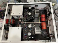
So this is my plan, i would love to upgrade the boards with better components such as doing a full recap of all the boards such as the preamp, amplifier board and psu etc
I also want to change any transistors and diodes which i have read can go faulty. I would like to build this amplifier to be like brand new and to last another 20-30 years.
So my questions are:
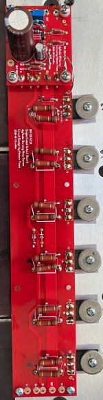
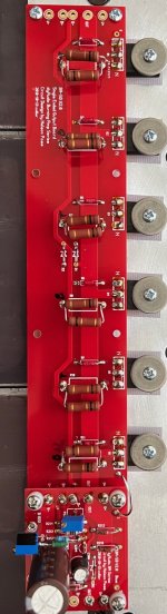
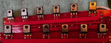
Is it worth replacing resistors? What resistors were used (type carbon?Metal film etc) The amp board would be easy to do i could replace all the components with new parts (not to sure about the bias resistors) they look odd and special heat disspersation types.
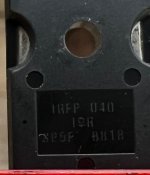
The amp board has other tiny driver transistors, do these tend to go and would it be a good idea to replace these?
I am slowly going through the circuit diagrams to understand it all better, i also know over the many years they changed components and always upgraded or made changes.
I will start with the 621 by just replacing all the capacitors, diodes and small transistors to get it working and running as it should. The 625 will be where i play around with it and try to upgrade the components.
Any advice would be appreciated such as what the bias should be, where to measure the bias, known things that should be checked, changed, replaced etc.
One other thing is the potentiometers on the 621 are very stiff unlike the 625 which feel smooth to turn, the input selector on the 621 takes quite a bit of force to click into place, where as the 625 is smooth and doesn't take me to squeeze my fingers hard to turn it. Wondering if spraying detox in there will solve this issue.
From what i have read the 600 range were modular and share the same boards
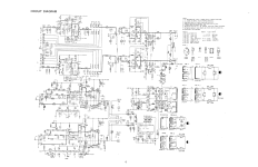
C28 input board
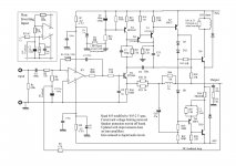
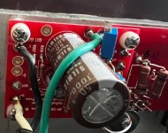
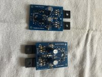
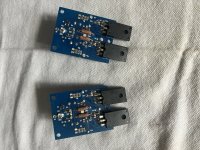
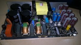
A17 power board
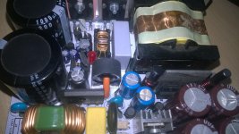
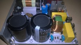
Z20 power supply
which means i could actually swap boards from the 625 to the 621? The 625 seems to be more modern.
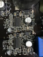
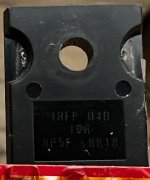
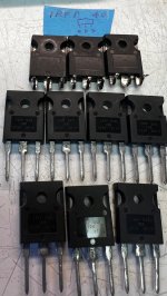
Also can anyone tell me good replacement parts for these parts
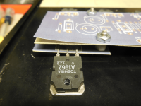
BC267 & BC297
BC384L transistors (would like similar or better i.e lower noise)
The bias trimmers seem old and risky to use would like to replace these with some bourns what power value would suffice here they come as 1/5w to 0.5w.
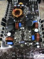
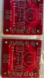
On the A17 power board there are some axial capacitors
2 x 220uf 50v and 2 x 47uf 100v which are polarised, could i replace these with non polarised (i have some which are of good quality and make).
The z20 power board has some tiny 1n4003 rectifying diodes could i replace these with something better like schottky diodes?
I also see many small eirie type capacitors of small values, thinking these would need replacing aswell? think these are Poly film types. Could i replace these with polyester, polystyrene or silver micas? lots in the tone control board!
The psu smoothing cap is 3300uf would it be ok to go slightly bigger? say 4000-6000uf? same goes for the DC speaker output caps which are 4000uf wondering if going slightly bigger has an advantage?
For further information!
The Armstrong 600 Series - Amplifier FAQ and diagrams
Yes its worth spending time and money to rebuild this back to its former glory! Any tips or things to look out for would be great.
Thanks all those interested!