Hi all, sorry if this is a little redundant...
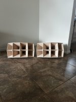
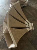
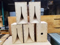
I've had a Logitech Z-5500 for like 15 years now on my various Desktop PCs. I've been super happy with it overall, but we've had a wild ride together. Several years ago, I replaced the main L/R speakers with 2 small bookshelf-size that I built with help from the kind folks here, using 3" MarkAudio drivers. They sound great. The rest of the system is stock.
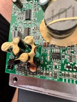
Recently, I've started hearing some pops and crackles (almost a sizzling static) from all speakers when there's no other output. I'm afraid the amp, or some other internal component, is finally about to let out the magic smoke.
I would like to begin investigating options for replacement. My current PC (just built), has a Creative Sound Blaster AE-5 Plus sound card, so I'm working with 3x analog outputs that need to be accepted by whatever sound system I buy/build. I'd like to use my current main speakers, and I have 2 Definitive Tech surrounds that might make good rear or center speaker(s). Beyond that, I'm looking to buy/build whatever I need. I'm not interested in going the full AVR route. I've tried that once before, and not only do I not really have the room for it, I never got the inputs and outputs to work correctly with Windows. Also, I've heard about routing sound through HDMI via my video card, but that doesn't appeal either, since it involves a 'phantom monitor', which invokes all sorts of additional issues.
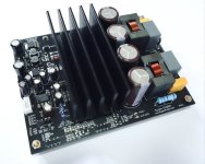
I thought about something like the
Aiyima A09, but the one actual review I found of it wasn't encouraging.
As for the Sub, I would probably go with a
Polk PSW10, unless you folks have a better suggestion in the same general price range. I've installed 2 of those in homes for friends, and they are solid units with good sound for the price, in my 'very much not a professional' opinion.
Bottom line: I'm looking for something that will sound as good or better than the Z-5500, doesn't take a degree in electrical engineering to set up, and won't totally break the bank. I'm not 100% fixated on 5.1, either. If there's such as thing as 3.1 (L/R/C/Sub), I'd consider that as well, if it sounds good enough. My rears aren't really mounted properly anyway.
😉
Any suggestions greatly appreciated!
I actually asked this question a couple years ago, and got no response. I'm hoping this time will be better.
🙂


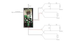


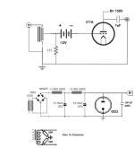


![TDA1543DAC US[1].GIF](/community/data/attachments/1251/1251265-a24ae3e0bea8d77b2f2dbd77bbd92423.jpg?hash=okrj4L6o13)