Hello fellow audio "big spenders"

As you already know, this is a glimpse into why I desperately need access to this forum.

I'm too poor to afford gazillion of dollars equipment so I'm here in hopes to expand my knowledge over technicalities of audio as a hobby so um............

yes, its a disease and i have to live with now 😀😀😀

as many of you, ive been once hopeful and young but now i approach 30 and im deserted without audio xD

i have a very "pleb" system but it does the job for me.

the guy that spread this condition to me showed me the first steps and tips&tricks about how to get around simple upgrades so that's about it.

hope i won't upset people around here but i ask lots of stupid questions :')
  • Thank You
Reactions: Foan

EMU 0404 USB no power

Hi there!

I've had my trusty 0404 for ages. Used it for a long time on my PC but then got fed up with driver issues on WIN10 and bought a Focusrite instead. I was always really happy with the way the 0404 sounded though.. it was really good both on headphones and speakers.

Couple days ago I decided to bring the device back to use on another system but it died on me. At first I managed to get it powered on and working normally but it was really picky about the way the DC adaptor plug was seated inside the unit. I would get it to work only when I twisted the adaptor plug/cord to an angle. When I released the cord, power would cut out. I did what any lazy guy would, taped the plug in the right angle on top of the unit and enjoyed the ride. But now after a day, I can't get it powered on at all. The poor connection must've damaged something inside.

I opened the unit to see if the female plug on the unit had come loose from the board, but I'm reading 5 volts on the female plug pins. I resoldered the pins, but this didn't do anything. I checked the power switch for continuity and it seems to be ok.

How do I need to measure voltage to see if the unit is getting power? Most logical thing would be that the DC socket has failed but I don't understand why I'm reading normal 5v on the pins. I tried another DC power supply but this didn't help either. I would really appreciate it if anyone could point me in the right direction. Many thanks!

Forte model 2 settings. Is anyone familiar with this preamp?

I know this is an older unit but has many favorable comments over the years. I just picked one up to try it out as my main preamp (Parasound PLD 2000) seems to be having problems. My phono stage may also be having problems, still tracking things down. I use a Cary PH301 phono stage but am trying the Forte out for now. My cartridge is LOMC FR1MK3F. Have AR 9's bi amped with 2 Parasound HCA 2200 II amps. I've enjoyed this system for around 20 years. Things may be starting to wear out. Looking into repairs, upgrades and possible replacements but more into the idea of repairing the "old". First thing I'd like to know is about the cartridge settings in the Forte Model 2. I have a copy of the settings but not entirely sure what they mean. If anyone is familiar, that would be great. If I should be on another forum, let me know. Seems like many good minds to pick on this site as I've been lurking and reading for some time before joining. Thanks for any advice.
  • Like
Reactions: Ixnay

Class D blokschema

I am not a real DIY-er but for financial and audiophile reasons I have put together a Hypex Ncore amplifier. Because I wanted to know how everything works I also read the publications of Hypex about this kind of class D amplifiers. What I understood about it I have recorded in a block diagram. See: https://www.dropbox.com/scl/fi/5gxy...ey=ljwb6u7x08l7n1ou0wnghtl59&st=4th8fvyt&dl=0
My question to this community: is that somewhat correct? Feedback is welcome.

What also surprised me is that apparently there are no class D amplifiers with a direct digital input, they are all analog amplifiers with possibly an A/D converter in front of them. In my opinion, such a class D amplifier with a direct digital input would be possible according to block diagram 2. See: https://www.dropbox.com/scl/fi/1ibp...ey=vufbmcdbf78zp2xd0oco6v5cs&st=roewukiz&dl=0 Again, feedback is welcome, even mocking laughter (with an explanation why) is very welcome

6LU8 PP help please

Hello folks I am in the build process of a point to point 6lu8 push pull amp. This is my most complicated point to point yet, and it is a real rats nest. I am following a previously published design by DIYAudio member Jane. (Circuit attached) This is my first PP build. I am now at the point where I am checking DC voltages. I am pretty confident I have it wired correctly. The voltages are in the right zone now I need to refine them to my conditions. I understand, that my transformers are not the same as the ones he chose and some adjustment may be needed.
Tube1 Tube2 Comment
pin# voltage Voltage
1 80 80 referenced to 1/4 B+
2 108,2 187.5 B+, Tube 1 is high, tube2 is low compared to the schematic. should be 90v and 200v
3 - -
4 311 311 output plate, seems about right
5 - -
6| 1.8 1.6 not sure, I think it is bias voltage from balancing network circuit
7| - -
8 115.6 115.6 screen voltage a bit low but the best I could do with the Zener diodes I have for now. should be 120v
9 14.2 14.2 Seems real low should be 18.
10 0 108.3 tube 1 is correct. Tube 2 seems wrong but is as per diagram for Cathodyne inverter should be 90v?
11 1.4 109.1 tube 1 is as per diagram. tube 2 is high compared to diagram should be 92v
12 80 80 B+ reference

Now for my questions:
1.) When trying to get things sorted out and bring the voltages more in line with the diagram, do I start at the output stage to bring the cathode bias up to the 18v target. I do not seem to have 5v on the 10k adjustment pot I only have 3.8v. I am only pulling 40ma through to pin9. I think I should change the 82R/220R but not sure which one or how much?

2.) The voltage on the Cathodyne is too low. The only thing I can think of is to change the pair of 39K resistors, or the 3.9k B+ resistor in front of the phase splitter. If I change the 3.9K then the voltages on the triode section down stream will also need adjustment to bring the triode B+ down to 90v.

I am expecting a few other things. Right now I am not real sure how to proceed. Some encouragement and help is needed.


Thanks for the help

Attachments

Goldring '88' design - Schoolboy 'howler'

...unless mine is non-standard.

The problem (- or just skip to....)

With the mains supply to all equipment disconnected there's an audible low frequency "dong" bell-like sound from the deck after the on-button is firmly pressed, but not the off button.

With the system live, the stylus lowered onto the motor-unit itself outwith the platter and the mains supply disconnected from only the motor unit, the bell sound can be heard plainly through the speakers. It takes just a small touch anywhere on the deck to excite it. This situation is begging for acoustic feedback problems, which I do have and is what prompted me to begin poking around.

I thought it would be caused by the unsuported idler wheel tension spring ringing like a guitar string. There was no similar sound after pressing the off button, when the spring is under more tension. Won't do any harm to thread a section of soft silicone rubber impregnated glass-mat tube (intended for high temperature electrical insulation). This noticeably damped the spring while not affecting its operation. Made no difference to the problem at all.

I played an LP and allowed the stylus to remain in the run-out groove. There was the usual 33rpm thump - which had its usual unique sound depending on which LP. Through the speakers the thump had a quiet but plainly audible dong after it. On simply unplugging the mains power to the motor the platter gradually slowed. The thump lowered in pitch but the dong didn't. Interesting little problem here.

Having a good poke around under the platter I noticed the metal strip which moves with the on/off switches and is bent up at its end to withdraw the idler arm and idler from the motor and platter.

With the machine in the 'on' position it went "dong" when I tapped it. When the machine was set to 'off', it didn't. This was because in the off position the end of the strip was in contact with the idler arm and therefore damped, and when in the on position it was a steel strip supported only at one end.

...the Solution.

I wrapped some handy Velcro "One-Wrap" around the metal strip so that it ocupied the small distance between it and the motor unit's cast chassis. Anything soft could be used. It completely stopped the dong. There was a slight increase in the pressure needed to push the on and off buttons as the One-Wrap rubbed against the chassis.

Obsevations

Absolutely amazing that the 'small beyond belief' stimulus from acceleration of the mass of the stylus in picking up the run-out thump was enough to excite the resonating metal strip, and for that to be so plainly reproduced through the speakers.

It just goes to show just how precise and sensitive these instruments are. A real learning experience. Maybe there's a bit less snake-oil involved in the HiFi business than I thought there was.

Denon DN-2000F not spinning

Hi there,

Relative noob here with limited skill, hoping someone can point me in the right direction.

I've recently acquired two Denon DN2000F Mk3 CDJ units. Some of you will be familiar with these I'm sure, classic kit from the early/mid 00s.

Both came to me (from different sources) as 'spares or repair'. In both cases, the initial issues were obvious: loose pulleys on the CD players, and a glass fuse on the main board that has blown as a result of trying to operate the players with said loose pulleys. All easily replaced, and I was hoping they'd be good to go after that.

However, now both units open and close and load discs happily, I'm left with the same issue on both. They steadfastly refuse to spin up or even attempt to read discs. Put a disc in the tray, close it, and where you'd expect there to be the usual CD reading noise, motor spinning round, track number displayed etc - nothing. It's like they don't know the disc is there.

I've tried all the obvious generic things I can think of:

  • lenses cleaned
  • all moving parts greased
  • ribbon cables are fine (swapped with ones from a definitely working unit, just to be sure)
  • control units seem to be ok
  • no leaky/bulging caps on the main board.

What seems strange is the same issue affecting 2 units (4 players). What I'm hoping is that it's therefore something really obvious that I've done when opening them up to sort the pulleys and fuses. But it beats me what that could be.

Help!

JBL 6260 Circuit

I'm just trying to work out this circuit of this JBL 6260...

I notice the VAS seems to run 'hot' in temp and also the drivers Q30,Q19, Q31,Q21 are also hot. These all have heat sinks but I'm surprised how hot these are running, 60 degrees approx. Why do they need to be so hot? All of these are the MJE340/50's I pulled out the drivers and measured the hfe. The NPN's it was very low around 20 but the PNPs were over 100. I put in MJE15030/31's instead which had higher gain.

I take it the outputs are in an emitter follower?

The current/voltage protection seems to be a conventional VI limiter transistors. DC protection seems to involve an opamp that will trigger relay over a determined voltage. There is also delayed startup to avoid thumps.

The interesting thing is these amps have quite a bit of hiss on output even at 0 gain.

Distortion was respectable at 0.0040 @ 1Khz and 0.0051 at 20Khz at mid power.

Bias set at 540mV between base and emitter on the outputs.

I believe this amp was marketed as a 'low feedback' design at a time where TIM was a thing.

Screenshot_2024-11-03_11-49-44.jpg20230624_083505.jpg

Kicker ZR600

I have a Kicker ZR600 in for repair.
The -15v power supply was blown, TIP30C (with MJE15031) and LM7915, 2x tantalum caps (preventive) and zenerdiode D17 were replaced.
I have -15V and +15V measured on all the opamps back.
But still have on both the outputs +40Vdc, speakerrelais not engaging.
Then I replaced all the opamps which (TL071 feedbackloop and TL072 inputs) were on +15V and -15V, but still +40Vdc .

I use the ZR1000 service manual, but some values are not clearly readable on the pdf I have.
Is there a ZR600 manual available?

Thanks!

Improvement advise on my current setup

Hello to all,

I'm looking for some improvement advise on my current setup.
My basic sound chain looks like this: Qobuz > Raspberry pi 4b (8gb mem) > UPMPDCLI / MPD > USB DAC (smsl sanskrit 10-edition mk-III > Wolverine amp > Kef reference model 3's from the nineties.
The raspberry (and dac via usb) are powered by an 5volt IFI power supply.
My mpd.conf and asound.conf look like this:

mpd.conf
Code:
audio_output {
        type            "alsa"
        name            "SMSL USB AUDIO"
        device          "hw:0,0"
        mixer_type      "none"
        mixer_control   "SMSL USB AUDIO "
        auto_resample   "no"
        auto_channels   "no"
        auto_format     "no"
#       mixer_index     "0"
}

asound.conf
Code:
pcm.!default {
        type hw
        card 0
        device 0
        periods 2
        auto_resample no
        auto_format no
        auto_channels no
        defaults.pcm.rate_converter samplerate_best
#        buffer_size 8192
#        period_size 2048
#        period_time 200000
}

pcm.!default {
    type plug
    slave {
        pcm "hw:0,0"                # Replace with your DSD-capable DAC device
        format DSD_U32_BE           # Set the format to DSD 32-bit Big Endian
        rate 176400                 # Use the correct rate for DSD64 (adjust for DSD128, etc.)
        channels 2                  # Stereo output
    }
}

ctl.!default {
        type hw
        card 0
}

I further more have set the I/O scheduler to none
Code:
root@DietPi:~# cat /sys/block/mmcblk0/queue/scheduler
[none] mq-deadline kyber

I'm using upmpdcli to use the pi as renderer controlling it with Linn Kazoo or any other controlpoint which works with upnp/opnehome. In upmpdcli.conf I've got the following config:

upmpdcli.conf
Code:
# Enable UPnP AV services (0/1).
upnpav = 0
# Enable OpenHome services (0/1).
openhome = 1

# Use external command to manage the the sound volume (0/1).
externalvolumecontrol = 1

# Command to run for reading the sound volume.
getexternalvolume = /usr/local/bin/get-volume.sh
# Command to run to set the volume.
onvolumechange = /usr/local/bin/set-volume.sh

# The name of the room where the Product is located.
ohproductroom = Zitkamer

I've created 2 bash scripts: get-volume.sh and set-volume.sh which controls the volume directly using amixer

get-volume.sh
Code:
#!/bin/bash
amixer get 'SMSL USB AUDIO ' | grep -o -m 1 '[0-9]*%' | tr -d '%'

set-volume.sh
Code:
#!/bin/bash
amixer set 'SMSL USB AUDIO ' $1%

Furthermoe I've added the autosuspend = -1 setting to /boot/cmdline.txt. Whetehr or not that helps...I honestly don't know🙂
Code:
root=PARTUUID=e87e153f-02 rootfstype=ext4 rootwait net.ifnames=0 logo.nologo console=tty1 usbcore.autosuspend=-1

Looking forward to any comments on this setup...
thx in advance

willem

Diffraction Horn Side Contour

Dear @DonVK and @fluid ,

I’am trying to design a diffraction horn for use with a B&C DCX50 compression driver. I’ve read yuichi arai’s book about diffraction horn design but unfortunately he doen’t explain how to derive the horn side contour analytically. This weekend I tried to investigate on this. Judging by the measurements he includes in his book, it looks like in the A300-E design he uses the height contour (from excel tool) of the horn decided by 1.5. In contrast in the A290 seems to use a narrower contour i.e. height contour divided by 2.

In your blogpost (https://sphericalhorns.net/2023/04/09/the-mk3b2-radial-fin-horn/) you depict a top view from your optimized horn. How did you come up with the side contour? Did you derive it from the fin counter generated by the excel tool? It looks more rounded. Obviously u have chosen half channels on the sides with a straight outer wall.

Attachments

  • mk3b2_fins-768x478.jpg
    mk3b2_fins-768x478.jpg
    24.4 KB · Views: 62
  • Bildschirmfoto 2024-10-25 um 16.50.48.png
    Bildschirmfoto 2024-10-25 um 16.50.48.png
    380.9 KB · Views: 53

For Sale Transistors Hitachi 2SB716 2SD756 Hiraga Le class A Le Monstre

Transistors can be used in Hiragas Le class A and the Le Monstre Amplifier. For sales 160 pieces 2SB716 and 2SD756 low noise original Hitachi. They are original Hitachi bought in the 1990s. The 2SB716 and 2SD756 can be used for Jean Hiraga's "Le Monstre" / The Monster Class-A 8W Amplifiers. Minimum order 20 Pairs for 24€. I have also some HITACHI 2SA872AE and 2SC1775AE i will offer them separated soon.

http://diyaudioprojects.com/Solid/Jean-Hiraga-Class-A-Amplifier/
http://diyaudioprojects.com/Solid/Jean-Hiraga-Le-Monstre/

Transistors can be sent worldwide with Finland’s Posti or Germans DHL plus 5% PayPal fees. Shipping by registered mail with standard PayPal payment, if as a friend via PayPal an unregistered shipping is possible

Attachments

  • 2SB716 2SD756 (1).jpg
    2SB716 2SD756 (1).jpg
    260.8 KB · Views: 115
  • 2SB716 2SD756 (2).jpg
    2SB716 2SD756 (2).jpg
    274.9 KB · Views: 120
  • 2SB716 2SD756 (3).jpg
    2SB716 2SD756 (3).jpg
    384.2 KB · Views: 118
  • 2SB716 2SD756 (4).jpg
    2SB716 2SD756 (4).jpg
    194 KB · Views: 124
  • 2SB716 2SD756 (7).jpg
    2SB716 2SD756 (7).jpg
    210.9 KB · Views: 104
  • 2SB716 2SD756 (8).jpg
    2SB716 2SD756 (8).jpg
    257.4 KB · Views: 98
  • 2SB716 2SD756 (9).jpg
    2SB716 2SD756 (9).jpg
    520 KB · Views: 128

The Problems of Parallel

I have recently bought some quality SE OPTs that are 600R primary impedance. The thinking was that I could use 4 x EL86 in parallel with them since they are rated for 350mA current. EL86 is a high current low voltage EL84 and usually has 2.5K as plate load, so 4 in parallel matches well with the OPTs for impedance and current.

There are some good examples of Hi Fi amplifiers with paralleled tubes. Here is one from Patrick Turner with 3 x EL34 at the output tubes: Patrick Turner 100W ULAB1.
Patrick Turner 100W ULAB1 EL34.png


From my limited experience with this hobby, it seems that tubes parallel very well, as long as they are reasonably well matched, but their only foible is the Miller capacitance, which is capacitance in parallel so is the sum of each tube.

From the data sheet:
Skärmbild 2024-11-01 104107.png


Pentodes solve the capacitance problem with additional grids, so maybe it would not be an issue with the 4 tubes in parallel? There is a thread here ...
DiyAudio: Pentode Miller Capacitance, and which spec value to use?
... and from that it looks like it should not be a problem with Miller capacitance, even when it is compounded 4 times. However, if I want to be able to switch to Triode output then it is going to complicate the driver.

I know I have a long way to go before I realise this amplifier, but I would like to hear some thoughts on the sort of driver circuit I will need to satisfy the needs of 4 tubes in parallel, or if there are any special considerations to take on board. (Maybe it is a stupid idea!). It looks like oscillations can become more likely, for instance, and protection circuitry is more important. The output tubes will be self biased, so that is one simplification.

This thread from @Diabolical Artificer was an interesting read: DiyAudio: 120w PP UL monoblocks , with a quad of EL34s.

Scratched veneer repair

Hey,
I’ve got a nice pair of active speakers with a couple scratches on the veneer as seen in the pictures. The uppermost scratch is deeper but both are across the grain. If I just wet the lower scratch it disappears whereas the upper becomes darker and more visible. I’m looking for advice on how best to repair these.
Thanks

Attachments

  • image.jpg
    image.jpg
    1.1 MB · Views: 85

Wharfedale Glendale 3 XP Electrical / Bluetooth

Hi guys,

I received a set of Wharfedale Glendale 3 XPs and want to figure out how to make them work via bluetooth (I’m a total noobie!)

I bought this as I thought it was the right thing - https://www.amazon.com.au/dp/B08M3KX523?ref=ppx_pop_mob_ap_share

Now because I’m absolutely clueless with powering speakers, how can I power the speakers without accidentally burning my house down?
  • It says for use with amps up to 50 watts per channel, but then it also says maximum input 40 watts DIN, so to be safe I’d want to err towards 40?
  • What kind of power supply should I be getting? My current inkling is 19V but I’m not certain of the current
I live in Australia if that’s of any help.

Thank you so much for your help guys!

Advice for a Wire Assortment

Please excuse a very basic question. I'm getting ready to buy an assortment of wire for a couple of solid state amp projects, probably no more than 25 watt output. I'm thinking 22 gauge, in stranded and solid, and 18 gauge in stranded would be a good start. What are your thoughts?

I'll also be working a power supply for these amps. Will 18 be sufficient or would it be best to have 16 or 14 on hand?

Thank you for your help. I've been out of the electronics field for 30 years and my 60 year old brain just isn't clear!

Joe

For Sale Gilmore Dynalo PCB kits with matched transistors

Two Dynalo kits left with genuine well matched transistors available after getting parts for my own needs.

Included in Dynalo kits:
2 x Dynalo amp boards
1 x Golden Reference supply board
2 x THAT340 converter PCBs for Toshiba 2SJ74 + 2SK170BL JFETs (other adapters available for LSK489 & LSJ689, see pics)
32 NPN & PNP tightly matched MPSW56 & MPSW06 output transistors. (16 per board)
12 x well matched VAS/CSS transistors (6 per board)

Two Dynalo kits left
£50 GBP + shipping - EU should be around £7 tracked, USA £11 tracked

Attachments

  • IMG_0286.JPG
    IMG_0286.JPG
    967.2 KB · Views: 628
  • IMG_0289.JPG
    IMG_0289.JPG
    931.1 KB · Views: 505
  • IMG_0292.JPG
    IMG_0292.JPG
    734 KB · Views: 463
  • IMG_0297.JPG
    IMG_0297.JPG
    746.4 KB · Views: 491
  • IMG_0293.JPG
    IMG_0293.JPG
    643.1 KB · Views: 563
  • IMG_0298.JPG
    IMG_0298.JPG
    863.1 KB · Views: 613
  • Like
Reactions: Pars and itsikhefez

Focal Shape (65) Tweeter mod - Silk dome upgrade to Monacor DT-28N

I was tired by default aluminium magnesium tweeters sound of my Focal Shape 65, because I like much more silk domes tweeters that are, imho, more delicate and defined.

So I searched for a silk tweeter that could be dimensionally compatible without modifying or damaging the MDF cabinet. It's was not easy to find a good compromise, because the helliptical holes already present on the box are really small, so there were not so many decent tweeters that could be minimslly compatible.

I therefore found Monacor DT-28N tweeters, they have the right response and the right gain that will not make you regret the originals with alu-mag inverted dome.

Furthermore they can work until 50W rms and they have the biggest neodimium magnet available for a tweeter of that dimensions.

I therefore excluded the mass of chinese bulk tweeters that could not warrant any decent results.

Now the treble sound of my loudspeakers is crystal clear as I wanted !
As they are linear starting from 2Khz, also the low portion of treble maybe well aligned with original speaker specifications.

However, this modify is non disruptive so you can restore original setup at anytime you want with a simple screwdriver.

Here the link for the 3d printable support on Thingiverse:


Focal Shape Alu Tweeter Upgrade to Monacor DT-28N Silk Dome by Asterion72 - Thingiverse

Enjoy it !

Attachments

  • IMG_20211205_110603.jpg
    IMG_20211205_110603.jpg
    92.5 KB · Views: 454
  • IMG_20211205_111016.jpg
    IMG_20211205_111016.jpg
    77.6 KB · Views: 378
  • 61NgQSwwJ-L._AC_SL1000_.jpg
    61NgQSwwJ-L._AC_SL1000_.jpg
    124.5 KB · Views: 286
  • 61IRbJG6OzL._AC_SL1000_.jpg
    61IRbJG6OzL._AC_SL1000_.jpg
    152.1 KB · Views: 310
  • G104020K.jpg
    G104020K.jpg
    48.5 KB · Views: 314

Mark Levinson No 332 powers up but no sound (yes, its definatly my fault)

I have been enjoying my pristine condition Levinson 332 power amp for a couple years. It was serviced last year by a knowledgeable tech in Austin and has sounded wonderful since the cap replacement and adjustments.

I finally got my hands on a No 380 preamp to pair with my amplifier. The comm port between the two worked perfectly. Between the conveniences of the 380's remote control and the sweet sounds of the ML combo I was in stereo heaven.

That is until I plugged in a newly purchased pair of Klipsh Heresy I's that I planned to upgrade. I didn't test the speakers before attempting to listen to them and obviously there is a short in the crossover or something came loose in shipping. When I plugged them up and turned the system on I got about 5 sec of barely audible music. Without thinking, I slowly increased the volume. Immediately there was a quiet small pop noise and then nothing.

I have only been into DIY a short time and haven't done much more than TT mods or bookshelf building. I am addicted to the hobby, despite my inexperienced, but I am determined to get my beloved amp back.

From my blunder, is there something obvious that I should check in the amp? I have found all the schematics so kindly posted from user Levinson Mark for the 332. I dug up a wire resistor replacement instruction guide elsewhere. From the schematics and my basic base of knowledge, I believe I can locate the F301, F302, and F303 30amp fuses.

Before I open her up, I wanted to see if anyone would push me towards the most obvious source of the problem.

I am skeptical that either the fuses or resistors would have blown from a shorted bookshelf speaker, but honestly I am not very confident.

Anyone with pictures of the insides, an idea of what I may have blown, or any suggestions to get me back up and listening would be greatly appreciated.

Thank you in advance for any assistance.

Thread notifier suddenly stopped... no emails

Not receiving notifications via email at the moment...

Hijacking the first post to announce the availability of a new tool to allow diyAudio members to DIY their removal from our email suppression list.

Please visit the "suppression list removal tool" (SLRT) at:

diyAudio Supression List Removal Tool

This tool will:

  1. Explain what the suppression list does
  2. Check if you are on our email suppression list
  3. If you are on the list, tell you on what date and why you were added
  4. Automatically remove you from the suppression list

-Jason

A Purpose Built Class AB2 PP 6F6 Amplifier

6V6s in Class AB2
Here is a similar version of the amplifier proposed by Miles P back in 2007 (Tee-Vee T00b Amp). This one from the Summer of 2001. Altho the project results were posted on RAT at that time I never authored an article for publication. Real work got in the way. The transient results did appear in the Nov 2003 issue of AudioXpress later as part of another project.
This amplifier was not built with listening in mind. Or as a work of art. It is strictly experimental & satisfied some of my curiosities.
I had certain objectives in mind for this project.
1) PP 6V6s in Class AB2
2) NFB to the upper grids of a differential cascode stage
3) Transient performance of the amplifier while powered by a limited power supply
At that time 6V6s were still plentiful. And I had several in my stash. To run in Class AB2 the PP 6V6 loadline has been adjusted to 6.8K running thru a Hammond 125E Universal OPT. The 6V6s are driven by CFs in a 4BQ7. It avoids H-K problems by running on its own 5V supply. The B+ is 338V.
The idea for the internal NFB originated with Bill Perkins of PEARL. On a business trip to Calgary I made a point of visiting Bill. He was working on many projects, one of them included NFB from the output plates back to the screen grids of a earlier stage.
I reasoned that NFB back to the screens would be loaded by the pentode screens, why not try instead the upper grids of a PP cascode stage. The cascode stage is a differential pair of 6BQ7s with a long tail of 100K down to -150V. So the internal NFB is taken from the 6V6 plates. And the resultant internal NFB is ~8 db.
A Hammond 271X power transformer is sufficient to run the 6V6s in Class A. The rectifier is a full bridge of 1N4007 diodes so that both +ve & -ve voltages are available. The +ve filter is a CLC of 10 microF, 5H & 100 microF. The –ve filter CRC of 10 microF, 1.5K & 10 microF. Then 25K & a VR150.
I ran tests both using the amps internal supply & with an external regulated supply.
What would happen in the PS if the amp suddenly was required to pass a large transient signal? In some ways this was similar to what happens to a guitar amp when driven hard.
Attached are some of the test results I got recently when I pulled the amp off the shelf for another look. The Scope/SA is a PicoScope 3224. I used a Differential Probe for most of the measurements. For the burst traces the PS sag is the blue trace, the test signal One KHz at 10 Watts.
And it does sound very good. Bench tests are a very good predictor of success.

Attachments

  • 027 Cascode Amp B.JPG
    027 Cascode Amp B.JPG
    542.4 KB · Views: 165
  • IMG_1383 Cascode Amp Bottom A 14W E Flash  Labelled.jpg
    IMG_1383 Cascode Amp Bottom A 14W E Flash Labelled.jpg
    366 KB · Views: 202
  • Cascode Amp H.JPG
    Cascode Amp H.JPG
    65.8 KB · Views: 207
  • 2013_03_23_002.jpg
    2013_03_23_002.jpg
    67.8 KB · Views: 185
  • 2013_03_21_001 Peter Gabriel Salsbury Hill.jpg
    2013_03_21_001 Peter Gabriel Salsbury Hill.jpg
    77.9 KB · Views: 125
  • Pearl Page 8 30C.jpg
    Pearl Page 8 30C.jpg
    104.9 KB · Views: 146

Dynaco - ST 400 PC-29 mods/upgrades

I am restoring a ST-400 with meters that I recently found locally.

The PC-29 has been modified:

  • Traces to the filter switches have been cleanly cut/severed
  • The pins in the filter switches had been removed (I bought a NOS double switch assembly from Vintage for replacing them)
  • Two jumpers have been installed in the back
  • Several wires have been soldered to a kind of post on 22
  • 7 and 8 are bridged by solder.
  • R19 missing/removed
  • Two D5 have been disconnected on one side
  • Two D6 have been disconnected on one side

Could it be a modification for by-passing the Dynaguard with or without keeping the audio?

Are they any papers/articles on modifications/upgrades on the PC-29?

I have seen a post from audiobard (May 10, 2010) Originally Posted by audiobard: ... There is an article in TAA (The Audio Amateur) 3/83 by Bill Rollins about an update of the stereo 400. I have a copy on paper, but not yet in electronic form.I'll try to scan it as soon as I can and mail it to you if you are interested...

Can someone send it to me?

I am also replacing few parts for PC-28 amplifier circuit boards as per Kevin Baoles' article (Dynaco Repairs For PC-28 Amplifier Boards)

Any articles on upgrading the PC-28 and PC-30?

Lifespan of your soldering irons?

Hi - I have a weller WE1010 and it has stopped working (screen blank) I spoke to weller and there is no spare PCBs so that's a load of materials for recycling it seems 🙁

Anyone recommend somethign that can last 10+ years rather than 4 hrs of light use. In context I have used about 1/3 - 1/2 of a reel of 500G of solder in the life of the iron.

Thoughts?

Science of "bypass capacitors" in crossovers

What might be behind the reported effect, that the sonic qualities of very small value bypass capacitors are remarkably imparted on the sound?
If it's into the hundreds of kHz range where the bypass cap has its lowest impedance and is somewhere like at least tens of ohms in the audible range, how could this translate to audible improvements?
I believe it does, enough credible-seeming people say they hear the difference. Would like to understand this phenomenon, technically.

What kind of non-linear interactions might happen when using a 0.047uF or 0.1uF capacitor in parallel to, say, some tens of uF?
  • Like
Reactions: cyberstudio

Passive cut EQ Question

Just a question and looking for advice:

Scenario: Car audio system that offers no real control over EQ. Speakers are harsh around 2.7kHz and 4kHz. Has anyone seen or designed a passive filter to cut frequencies like this on the speaker terminal itself (as in a crossover, but only to subdue specific frequency ranges)? Like the illustration below, I'd love to tailor the "Semi-Treble" but to adjust the Q. Would this be a relatively easy design? Once I find the right values, I can build exact resistor/capacitor values for all the other speakers. Any ideas? Thanks so much!


Screenshot 2024-11-01 at 2.07.28 PM.png

Hallo

Hello everyone! I have been an audio fan for as long as I can remember. I started tinkering some time ago, I am a beginner and sometimes I need help. I made 2 DIY kit amplifiers, one in a housing that I made myself, a few preamplifiers (DIY kit) and bookshelf speakers. Now I am working on the Dartzzel Nhb-108 on the original diagram.

Attachments

  • IMG_20241006_204954.jpg
    IMG_20241006_204954.jpg
    608.3 KB · Views: 36
  • IMG_20240929_201057.jpg
    IMG_20240929_201057.jpg
    499 KB · Views: 39
  • IMG_20240907_215633.jpg
    IMG_20240907_215633.jpg
    275.6 KB · Views: 33

Sorry, newb needs X-over input

Hi Y'all,

I've been playing with Vituixcad for a bit and I think I'm almost where I understand the process. Still not sure about the merging of enclosure tool SPL/Z... but I not sure if it matters too much at this point as I'm more focused on the crossover and the enclosure for this woofer has already been designed, esentially I'm working on a version of P. Blix's MLTL using the Peerless 830656 and the Peerless DX20BF00-4 as the tweeter.

I've done the work with the difraction tool and I think I've merged the baffle step correctly and this is the result of quite some time of tinkering.

1720658478079.png


Directivity and Power Response are both quite lumpy though, and I don't know if there's anything that can be done. Optimiser does flatten both out a little, but it moves the x-over quite high and phase separates - so i'm not sure if thats any better or not.

Thanks in advance for any input.

P.S. I've googled quite a bit and I couldnt really find previous examples of crossover of these drivers to look at - so if you know of any kindly direct me.

Accuphase C47 wonky amp circuits

Amp board.png


I'm trying to reverse engineer the amp circuits here, but I'm getting stuck at the RIAA amp. It's a differential amp with normal and inverted outputs so theres 2 RIAA circuits for 1 channel.
If you look at the SOT-89 output transistor pairs, at the top, right of the 3 relays are the pairs for the normal and inverted output.
And below them there's the rest of the amp circuit.

The CBL transistors are NPN 2SC3324
The ABL transistors are PNP 2SA1312

Here's as far as I've gotten with the circuit. I'm stuck at the weird current mirror thing consisting of Q22 Q24 Q33 Q31. etc.
The only connections to that circuit are the Q22 and Q31 bases/collectors; the 2 150 ohm junctions. And the 300 ohm resistors which are most likely tied to the power rails.
Then there's also the 2 2k resistors for no idea what.
RIAA Amp.PNG


Here's where I think the traces on the other side of the board are. There doesn't seem to be any parts on the other side since nothing seems to be missing... Apart for the other output amp, since it's a balanced output, but maybe it's just pseudo-balanced.
Traces.PNG


Here's the schematic for the output amp circuit which is on the lower left of the board. It's pretty much complete.
Output amp.PNG


Maybe it's just a biasing circuit, but how does it handle both output stages then? And if so, why is it only there for the RIAA amp.

Here's also a very incomplete schematic of the input amp if it gives any ideas.
Input amp.PNG

For Sale Closed-back MrSpeakers AEON Headphones

I'm selling some rarely used hi-fi items to make space for new projects.

For sale: a rarely used MrSpeakers Aeon closed-back headphone, purchased around 2018. These days, the company is now known as Dan Clark Audio. The earpads have degraded over time (see photos), but replacement earpads are available for $60. I'm asking $290, firm. I have the certificate of authenticity.

Prefer local pickup in the Bay Area.

1730575992009.jpeg
1730576023283.jpeg
1730576037276.jpeg
1730576052478-jpeg.1376144

Attachments

  • 1730576052478.jpeg
    1730576052478.jpeg
    269.3 KB · Views: 164

For Sale Audiotechnology 18H52 17 06

Hi all

I am selling a pair. Only note the marks of the screws and a small cut in the suspension of one of them. See photographs for more details. Original packaging.

Price for the couple €320 + shipping + Paypal fee

Regards

Attachments

  • IMG_20240331_185611.jpg
    IMG_20240331_185611.jpg
    158.5 KB · Views: 127
  • IMG_20240331_185621.jpg
    IMG_20240331_185621.jpg
    680.5 KB · Views: 165
  • IMG_20240331_190023.jpg
    IMG_20240331_190023.jpg
    134.2 KB · Views: 159
  • IMG_20240331_192251.jpg
    IMG_20240331_192251.jpg
    281.5 KB · Views: 159

Help w/tweeter-mid passive xover

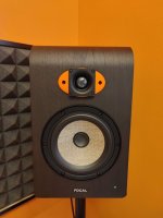
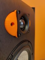
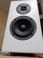
At the risk of coming off as overdemanding & scattered, I ask for help with another project: create a passive crossover to go between a GRS version of the NEO3 planar tweeter & the old Peerless/Tymphany NE123-8. https://loudspeakerdatabase.com/Peerless/NE123W-08

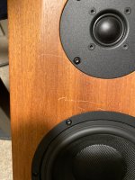
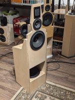
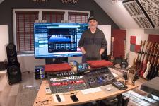
These are used in a 4-way active speaker that was a clone of the Linkwitz LX521 that I built last year for my son. I just converted it to a monopole closed box bass speaker. My son changed his mind about what he wants to do with the speakers: before, sound great, no need for real loud. Now, real loud, especially for deep bass. Force-cancellation OB Peerless SLS10 woofers did not cut it.

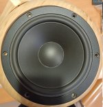
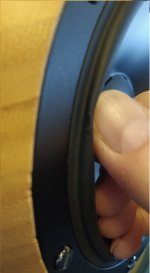
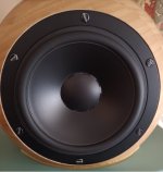
It took a lot of swearing and work but I managed to shoehorn a Dayton RSS265HF-8 to replace the original woofers. Now they are more like Juhazi's Ainograients -- monopole closed bass, OB above. No question this produces more deep bass at higher volume than the original config.

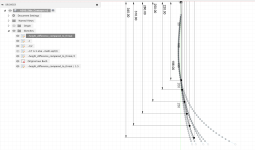
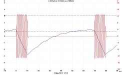
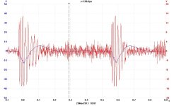
The new bass section has internal volume of ~1.3 cubic ft, stuffed with around 10-12 oz of teased long wool hair, a Q=0.68, Fs=39Hz, and within a foot of the wall behind, with +8 dB @ 35Hz, is down -3 dB at 30Hz. I doubt it can stay uncompressed to 100 dB, but that's probably good enough. So far, I have not heard the driver or 2x150W amp overload with music.

Before:
PXL_20231126_185214446.MP.jpg

PXL_20231126_185101185.jpg


Now:
PXL_20241017_175854696.jpg

PXL_20241024_175935150.MP.jpg


But as you might know from my recent forum posts, my son has expressed an interest in even more power/depth in the bass, which is mostly what is driving my investigation of subs and the SB Audience Nero 15" 800.

One of the challenges is the need for a 5th active band -- ie more than an 8-ch miniDSP OpenDRC-DA8 can handle -- and all the crossover complexity & expense this entails. In my son's home, such complexity is not really ideal.

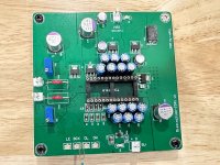
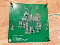
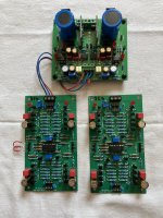
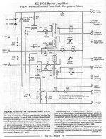
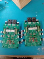
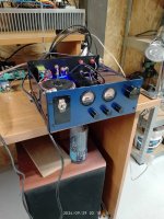
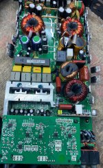
SO... my thinking is to go passive between tweeter & high mid to reduce the active bands in the main speakers to 6 so the subwoofer, when it's introduced to the system, can run off the DA8 directly. The amplifier I built for him uses 3 of Eric A's 2x150W modules and one 2x300W module (from DIYaudio's vendor bazaar). The latter can be bridged to 600W, to minimum 6 ohm load, which suits a Nero 15SW800 well.

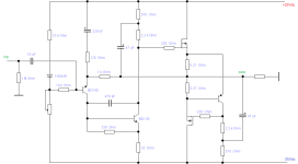
One day soon I have to learn to design passive crossovers with VituixCad, but that day hasn't come yet. Which is why I beg for your help. I'll provide whatever measurements are needed. I know it doesn't have to be perfect because PEQ in the miniDSP can be brought to bear, but it'd be nice to get close.

My target is acoustic (effective?) LR4 @ 3kHz. Open to LR2 & B3 as well. Tweeter needs 3-4 dB padding to compensate for its higher sensitivity.

I have a week-long window to pull this off, so there is time pressure. At least, I need to do all the raw driver measurements within a week.

Attachments

  • PXL_20231126_185101185.jpg
    PXL_20231126_185101185.jpg
    638.8 KB · Views: 46

Coral Holey Baskets

For the last 5 years I have been harvesting Sony TC500/500a tape decks for speakers and transformers. I think the time has come to create something from the parts I have accumulated. I have plenty of ideas I would like to explore for the transformers, but I currently have 8 pairs (16 speakers) of Coral holey basket drivers and am wondering what those with far greater knowledge than me would do with them, given the chance. I have looked over the numerous past postings, but could not really find an example of anyone with a large number of drivers. I can certainly produce multiple different speakers, each using one, or two, pairs, but wondered if that would be a waste of a rare opportunity. Thank you in advance.
  • Like
Reactions: Wik

Hello, Audio Experts and Fans!

Hello,
I'm an Audio Mastering engineer near Nashville, TN. My interests widely dive into Acoustics, room correction, and tailoring audio to sound great on many systems. I'm hoping to learn a few tricks here to build something sellable to the world of car audio. I'll post that soon.

Thanks for accepting me here! Have a great week!
Brian

Attachments

  • Screenshot 2023-12-14 at 10.11.22 AM.png
    Screenshot 2023-12-14 at 10.11.22 AM.png
    5.3 MB · Views: 1,648
  • Like
Reactions: tomchr

Bluetooth receiver, buzzing even when disconnected.

I have recently tested a Bluetooth receiver with audio output with a pair of amplifiers and different power supplies, but it continues to emit a loud buzzing and noise that covers any audio track. I have seen that there are many people with this problem and also many solutions to this ground loop, but in my case the problem occurs even using two separate power supplies and even disconnecting the BT completely from the amplifier: even connecting only GND and VCC to the receiver and observing the R or L output on the oscilloscope the same audible noise is present, yet it is not connected to anything!

Is it possible that it is a defective model? As you can see from the image, there is also an unsoldered pin of the IC, where the pad is completely missing.

Attachments

  • P_20241031_203957.jpg
    P_20241031_203957.jpg
    266.4 KB · Views: 48

NVX

This amp protect Led is on but it is not in protect. I see oscillation on all channels but it has no output.I think it is in mute.I see 12v on the mute pin.Also R15e was open.

Any suggestions

Attachments

  • IMG_4044.jpeg
    IMG_4044.jpeg
    1.1 MB · Views: 63
  • IMG_4043.jpeg
    IMG_4043.jpeg
    1 MB · Views: 58
  • IMG_4042.jpeg
    IMG_4042.jpeg
    1,021.5 KB · Views: 57

Help Adding an Inductor to a Yamaha T-50-C Amp

Hi all! a bit of background: I've no problem working on solid state amps, but am less knowledgeable when it comes to tubes, but love the sound of a tube amp for my guitar...
Here's the issue: my Yamaha T50C has more hum than I would like, particularly when running in "Overdrive". I read an interview with Mike Soldano where he mentioned that one of the changes Yamaha made to his design, which he didn't like, was removing the inductor from the power supply. He recommended putting it back, and that's what I'm thinking of doing!
So my question: how should I spec the inductor? More Henry's is better, no problem there, but less so is the DC resistance and the current rating. This isn't a "cost is no object" build, but I don't want to cheap out either! For a 50 watt amp, with a 500 vdc supply, running a pair of 6L6's, about what current rating should I be targeting? And how much resistance would be "too high"?
Cheers, Dave

Fir filter/convolution problem Jriver, Rephase& Rew

I have been driving active diy speaker setup:
Source--> Jriver --> convolution, crossovers 6h--> rme ufx--> amplifiers-->speakers

Crossovers are done with rephase and eq with the eq in the rephase

Convolution file is text .cfg form

This setup sounds good to me....

So then i just wanted to see what is the max out of my old Behringer truths b2031a's, so i decided to eq them flat. To get rid of that rising tweeter response. Took measurements with rew and imported them to rephase. Used the same linear phase eq in rephase as always...

Made two channel .cfg convolution file (Behringer left and right)

Imported it Jriver and started playing..

Sounds completely horrible! All the clarity is gone and its like dual mono but much worse. Soundstage gets really narrow to the center/middle of the speakers .

Problem is clearly in the convolution, because i tested it by importing the rew suggested eq correction (Hz,q gain) manually to the Jriver parametric equalizer and clarity came back and equing is working, makes the sound better than the factory set b2031a

Where is the problem?

Understanding Power Input Transformer from Spring Reverb Unit

Hi, I have been tasked with fixing this Carlsboro Spring Reverb unit from the 70s. Upon opening it and hooking it up to power, I noticed that the transformer connected to the 240V mains AC was creating sparks at the primary side.

I disconnected the secondary side to see if it was anything to do with the load and it still sparks.

I'm looking for some help understanding what the different legs on this transformer are doing. It looks like the live is connected to a center tap on the primary side, and then in circuit, the secondary side is connected across the full winding (the two outer connections).

The reason that I ask is that it seems like the output of this transformer is quite unstable, and I think this is making the rest of the circuit play up (inconsistent output volume). The transformer was sparking a little near the neutral input and gave a slight burning smell.

I've measured the output voltage with a multimeter and it moves between 9VAC and 13VAC. I'm guessing I want a 240V -> 12V transformer. Does anyone know if that sounds right for a unit from this time.

If anyone else has any more information on this circuit would greatly appreciate it.

I've attached an image of the unit: https://drive.google.com/file/d/1PC6jseZAoFp6y7S0jCCuBVUTVrBcKYZd/view?usp=drive_link
An image of the transformer: https://drive.google.com/file/d/1lWGa4cazlWKj6C2WJpXJeOmWTjdCqA-A/view?usp=drive_link
The transformer in circuit: https://drive.google.com/file/d/1Y2wx8A0PtAs1wylrxuNHHhk5cTzqkA7A/view?usp=drive_link

Thanks a lot

Rega Motor Wiring. What have I done wrong?

Hello,

My old Rega turntable has motor gone bad so I replaced it with below motor which was the cheapest that I could find.

DataSheet (Motor Type: 9904 111 31104)
https://www.farnell.com/datasheets/1765731.pdf?_gl=1*zww2k5*_gcl_au*MjEyMTY0OTk5NS4xNzMwMjgzNjMz

It is 220v 16mA 250rpm motor.

I am based in Australia and main voltage is 240v so I used 1.6K ohm Resistor to drop the voltage down to 220v and used 0.1uf X2 type Capacitor for direction of the motor.

However, the motor runs clockwise one time but when I turn off and turn on again it runs anti-clockwise and whenver I turn off and on, it is random 🙄

And, the torque is very weak and when I put the light platter on then it is struggling to turn.

It is brand new motor from Element14 and I would like to check if I did anything wrong before sending it off.

I attached diagram from Datasheet and actual rough soldered connection before heatshrink them properly.

Please correct me if I did anything wrong.

Thank you.

Attachments

  • 220v Motor Wiring Diagram.png
    220v Motor Wiring Diagram.png
    57.3 KB · Views: 125
  • Rega Motor Wiring.jpeg
    Rega Motor Wiring.jpeg
    82.5 KB · Views: 121

*tap tap* ...is this on? It is? Alright... Hello everyone!

I am a 22 year old audio enthusiast, I work as a sound tech for live events, and I recently picked up a hobby of servicing old gear, for now I've fixed 3 turntables and 2 cassette decks, and I wanted to make some gear myself, that's why I come here because my knowledge of electronics is, well... Lackluster so to say. But I can operate a soldering iron quite well, so with some guidance I think I'll manage. Have a nice day!

upgrading LM833 opamps in DSP

I see regular posts and debates here on improved, newer opamps. So I began wondering if this is something to consider for my favorite DSP unit, the Biamp Tesira Forte.
Unfortunately, I don't have the schematics but this is a BALANCED in/out DSP unit:
https://products.biamp.com/product-...A8B78ABC|204E989F-7D8B-4FB6-9BDD-C5B7739EBB65

I can say (because I looked inside) it has three LM833 for each channel input and three LM833 for each channel output. So theoretically, I can replace each of these opamps with something. Now the question is, with what and would it make a noticeable difference?

F5 layout

Wanted to make a layout for F5 as per fig 1 of http://www.firstwatt.com/pdf/art_f5_turbo.pdf for those who to want to etch their own pcb.

here it is. any comments on the layout welcome🙂.

the ground lift components (anti parallel diodes and resistor) are optional. LED and its resistor are also optional.
mosfet mounting hole center to center distance is 64mm.

Is it enough that the NTC touches the Heatsink?
reg
Prasi

Attachments

  • F5 layout Prasi-r1.png
    F5 layout Prasi-r1.png
    102.7 KB · Views: 1,330

  • Locked
Help request for enclosure design for a Smart Speaker with a TEBM46C20N-4B

Hello all

Im currently working to make a Smart Speaker that has a fully open source software stack, and a 3D printable enclosure (Eventually to be injection molded or milled) and would like to ask for some assistance desining an enclosure for a TEBM46C20N-4B

Ideally we are looking for the enclosure to be a 92mm cilinder, with the speaker down firing. The intended application would be for streaming music, and placed on a side tabel in a living room. Enclosure design is entirely new to me, and I dont know where to even begin.

Any advise as to how to design such an enclosure is greatly appreciated.

Miro PCM58 NOS R2R DAC Board

Sold . Thanks.

Warning : The sound of NOS R2R Dac is highly addictive.

For sale is a set of Miro PCM58P Dac board.
You would need to provide PSU with dual polarity rails +/-12V and a single rail +5V.
i2s source (Amanero USB-i2s, JLSounds i2soverUSB are some examples) to feed it in order to play music.
Look at the info in the thread to see the PSU requirements and information on the DAC board.
https://www.diyaudio.com/community/...s-input-nos-r-2r.354078/page-232#post-7085999

Board fully populated with good quality caps eg. Elna Tonerex, Panasonic FM ( to me , much better than FC), Vishay grey film caps, Samsung ceramic caps, Kemet blue film caps. good quality Nextron IC gold plated contacts sockets. Packed with high quality components.

This board also have u.fl connectors installed in case you would use them.

This is one of the spare board that i have built. All components, including the PCM58P Dac chips are bought brand new. They are populated to commission the board.
Each board has two new PCM58 chips.

I have a pair of genuine AD797 (from Element14 many years ago) to include as IV on the board. It is the only 'used' component on the board.

Some members said they prefer PCM58P than the PCM63P. It is up to individual and you have to try it yourself.
This is my very last PCM58 DAC board to sell. I would like to say that you would not be disappointed with the sound.

DAC with AD797 Op amps + Shipping registered with tracking = 125 USD
DAC without AD797 Op amps + Shipping registered with tracking = 105 USD

Paypal Family and Friends only please.
Check my track records in this group. Shipped 50+ packages to members here without a glitch. All received and happy.

For Sale Korg B1 Soft Heat by Zen Mod (Full Kit)

I've got parts for 20 full kits for Zen Mod's "Korg B1 Soft Heat" board for the DIYaudiostore Korg B1 Preamp.

Link to instructions here and a little build guide.

Kits are priced cheap ($6+shipping) for the board and parts. For those that already got a blank board, I'm willing to sell just the parts kits for $5 plus shipping.

More to come...after I build a couple and prove they work out. PM me if you'd like to grab one and I'll set it aside on reserve, to be sent out once confirmed it all works as expected.
20241113_072621.jpg

Recent Sophistication in Telemarketing

Got a call this morning from "Unknown, Unknown" on my iPhone 11. Normally I ignore such attempts at diverting my attention, but my wife being curious, took the call. After a few minutes haggling with the guy over his purpose for calling she whispered in my ear that she couldnt hang up!

I actually couldnt comprehend what she was talking about and gently taking the phone from her hand, I noticed the ordinarily red button that ends a call was green. She said it wasnt functional to end the call. I pressed it myself - no response. I immediately powered down the phone and left it that way for a few hours.

So, the "hackers" can now jump around - Blank - the display of the phone number they're calling from and the ID associated with that number.

They - apparently - can also take control of the basic functionality of the phone. If we werent dreaming, that is.

This is a new low in desperation IMHO. An attack on the basic sovereignty of the phone owner. Makes me wonder what other compute based devices can be infiltrated in such a way? I assume anything "connected"...

I know the European Parliament has the "Right to Repair" initiative. Hopefully, they'll start one called "Right to User Sovereignty". (That's not going to be a USA initiative)

Similarly - I feel - A fellow musician I was visiting remarked how he had Icons arranged across the screen of his W11 system, turned the laptop on one morning - all gone. He couldnt bring them back. I copied a directory to the "Desktop" in file explorer, the directory didnt show up there. At that point, I couldnt solve the problem for him, something fundamental got changed.

So it looks like others can just go into these devices and do whatever they want, perhaps limited for the time being. Where's User Sovereignty? Will we ever have it? Would you ever buy something without it? Will there be no choice?

"Hack" to add AVC to a Manley Stingray?

Hi, hifi people. I'm relatively new to line-level DIY, seeking thoughts/feedback about an idea rattling around my head:

In a nutshell: I'm thinking of bypassing the volume and balance controls in a Manley Stingray integrated amp and building an outboard chassis with its own input selector and an Autoformer Volume Control (likely one of the Slagle units).

Why? The Stingray has... let's call it a unique form factor, including dual mono input selectors located on the back. This achieves the amp's "short-signal-path-at-any-cost" philosophy by putting the user at risk of touching red-hot tubes when reaching for the knobs. No big deal for me, but a barrier for my wife since day one. Now we're about to update our living room/listening space — and the Stingray will move to a shelf inside a (well-ventilated) media console. (Crowding the top of that unit with a full-sized tube amp AND a turntable is a non-starter.)

Solution: A small, tastefully-designed component next to the turntable will fly. I'll get to see if the AVC hype is justified, plus a more tactilely-pleasing experience that hopefully makes wifey more likely to enjoy using the system.

Opinions, Please: I know what I'm imagining will work—the Stingray is really just a power amp with an input switch and passive volume/balance controls (see schematic below). But... does anyone think this is a bad idea, or have any reason to think a console-top unit with high end parts and an autoformer wouldn't sound at least as good as what's in the stock unit? AND... as long as wiper on the Stingray's pot is all the way over at ground, does anyone think the "sub out" right after the pots but just before the amp section wouldn't work just fine as an input?


Screenshot 2024-10-30 at 10.37.40 AM.png

Peavey 6505+112 Clean Tone not Working

I have a Peavey 6505+112, and the Clean Tone is not working properly. I can change between Rhythm and Lead Channel, with both the front panel and the foot switch. However, when I try to go to Clean Mode, the amplifier remain in Crunch Mode. I pressed the switch from the panel, and the foot switch led remains always off. It used to work before, so something blow off. I have the schematics but I have troubles to understand what could go wrong. Any help is appreciated.

Attachments

GRS PT6816 Improvements

I recently tested a GRS PT-6816 and am very impressed with the performance. From the get go I was reintroduced to what I consider to be the superior sonic presentation of a true dipole compared with conventional drivers. This is further benefited by the minimal and non resonant enclosure of the driver. The GRS seems neutral and fairly well behaved. It exhibits minimal audible distortion playing loud crossed over at 400hz-20khz. I consider it equal in performance to the best 3" full range and mid woofers that I've tested. An advantage I observe in addition to its dipole radiation pattern, and advanced elegant design and construction, is that it is extended like true tweeter, more so than any of the 2"-3" conventional cone drivers that I've tested. Though conversely, unlike said conventional drivers, 400hz is certainly the limit of its lower frequency extension. In addition a point source is a preferable design to a line source in my opinion and thus I wouldn't endeavor to use more than one or two of said drivers per channel in my explorations.

I observe a harshness in the upper mids and highs at louder volumes when compared with the highest performing small cone drivers and or a dedicated tweeter. While the clarity and istrumentation is equal only to electrostatic transducers, there is also a seeming albeit slight lack of dynamism and three dimensionality to the sound that the GRS produces.

I wonder if both aforementioned observations are reduced or resolved through the incorporation of a more elastic membrane and conductor as I intuit that "Polyethylene Naphthalate" is quite rigid, seemingly similar to mylar or kapton tape. In the interest of reducing high frequency resonances of the membrane, increasing low end extension while maintaining treble extension, and increasing effiency, I suspect that the incorporation of a slightly elastic membrane and conductor would set a driver of this design in a class above the rest. What would be such a material for both the membrane and conductor? Even at present, the GRS PT-6816 is my driver of choice for a near midfield two way or three way design.
Projects by fanatics, for fanatics
Get answers and advice for everyone wanting to learn the art of audio.
Join the Community
507,621
Members
7,880,405
Messages

Filter

Forum Statistics

Threads
405,874
Messages
7,880,405
Members
507,621
Latest member
DaveDiDosi