Surprising amounts of rectifier intermodulation

This is an instrument amp, but the topic I think is relevant here in 'tube section' as well...?

To be clear, this amp sound absolutely amazing. I actually believe it has something to do with the NOS late '60s carbon comps - but lets not go there...sorry.

The point here is I am a little surprised at the amount of rectifier (100Hz+) intermodulations. Look at the 1kHz test signal and the harmonics around it, they are 100Hz apart. The first +-100Hz are only -40dB down.

This is at max clean power just below clipping. With 6AX5GT rectifier this is ca 12watts and with solid state it is ca 18watts.

I think I have the layout and routing ok. The power supply is at one end, the first cap is really close to the rectifiers. The b+ wire (red) is routed close as possible to the GND copper bus. The loops should be farely small and tight.

I have seen this when the magnetics (power supply) is close to the OPT or IT, but here I was expecting a little better.

Any comments?

Is this just normal?

Attachments

  • amp.jpg
    amp.jpg
    311.1 KB · Views: 257
  • 17ohm_max_gridplatefft_ss.png
    17ohm_max_gridplatefft_ss.png
    66.2 KB · Views: 261
  • 17ohm_max_tuberect.png
    17ohm_max_tuberect.png
    68.8 KB · Views: 262
  • internal.jpg
    internal.jpg
    132.3 KB · Views: 272
  • external.png
    external.png
    602.5 KB · Views: 260

RIM Stereomaster

I have come across this old German amp on an auction site, a RIM Stereomaster, and there was a schematic with the listing which has stretched my understanding of tube circuits.

The amplifier is EL84 single ended output, with an EF804 driver and ECC83 input stage + tone controls. However I am finding it hard to understand the output stage.

There is negative feedback from the 4ohm tap on the output transformer.

The EL84 is DC coupled to the EF804. The EF804 has a capacitor to ground and some potential divider arrangement on its load resistor. The screen of the EF804 is coupled to the cathode of the EL84.

It is not completely obvious how the EF804 is getting its input, or how the feedback circuits work together.

Would be very interesting if someone could explain how the driver is functioning.

Attachments

  • RIM Stereomaster.jpg
    RIM Stereomaster.jpg
    544.7 KB · Views: 170
  • RIM Stereomaster cover.jpg
    RIM Stereomaster cover.jpg
    278.8 KB · Views: 169

24" hartley photos -

two nonidentical pair -

An externally hosted image should be here but it was not working when we last tested it.


An externally hosted image should be here but it was not working when we last tested it.


An externally hosted image should be here but it was not working when we last tested it.


An externally hosted image should be here but it was not working when we last tested it.


An externally hosted image should be here but it was not working when we last tested it.


`````````````````````````````````````````````````


An externally hosted image should be here but it was not working when we last tested it.


An externally hosted image should be here but it was not working when we last tested it.


An externally hosted image should be here but it was not working when we last tested it.


An externally hosted image should be here but it was not working when we last tested it.


An externally hosted image should be here but it was not working when we last tested it.


An externally hosted image should be here but it was not working when we last tested it.


An externally hosted image should be here but it was not working when we last tested it.

Where does Signal Ground come from? LM3886

Hi this is my first post.

I'm tinkering with an LM3886 circuit that I'm building in my spare time, mostly following the design from a website and partially following the reference diagram from the datasheet.

One thing that's confusing me 😕 is where does the Signal Ground come from?

Does the Signal Ground come from the amp PSU or from the equipment that is providing the audio source waveform (iPod, phone, computer etc)?

The website I'm following as the basis of my build has it coming from the amp PSU.

If it's really supposed to be from the amp PSU, how does the circuit complete itself (conventional current flow) with respects to the audio source equipment, if there doesn't appear to be a path back to the computer? (current flows from the computer into pin 10 of the LM3886 and then flows out via Signal Ground on the amp back into the house wiring?)

Thanks

Attachments

  • index.png
    index.png
    15.8 KB · Views: 451

Blaupunkt BPA 2120B

This is pretty different for me. This amp has like 6x separate small and large circuit boards in it, all single sided. I took a close look under a magnifier glass but could not find any solder issues to speak of.

I cannot get this amp to power up.

There are 2x30A fuses, and each fuse runs to two separate PS's which are running separate 494 PWM ICs on the same PCB. Each PS seems to have its own fuse. I can tell one of the fuses is drawing only 0.1A of power as when I pull that fuse the amp drops to 0A pull. The other fuse doesn't do anything.

The power LED lights up. Thats about all I get?

First 494:
1: 0.001
2: 2.440
3: 0.090
4: 4.93
5: 1.612
6: 3.782
7: 0.01
8: 4.97
9: 0
10: 0
11: 4.96
12: 14.02
13: 5
14: 5
15: 5
16: 0

Second 494
The only difference is pin 6: 5.04v. Everything else is same as first 494.

active blend pot, bass guitar

Finally I tested through the active EQ. But, I dont like how the blend pot works:
blend_pot.png
At the mid position, the blend sound is very prominent (and I like it most).
But as soon as I turn left/right, there is a very little room for smooth transition between pickups.
The tone abruptly changes towards one of the pups.

I think of buffering the pickups:
But I don't know how the circuit would handle short to ground (end positions of blend pot).

Buffering would handle the pot load and bring back some trebble.
Up til now, I was testing the pickups with no pot load - connected to amp directly.
The blend pot load seems to be 250k || 250k ~125k

Attachments

  • blend_pot.png
    blend_pot.png
    12.9 KB · Views: 195
  • buff4.gif
    buff4.gif
    1.4 KB · Views: 165

Help Needed with TSE-II Configuration Decisions for a First Time Tube Builder

I am building my first tube amp and would really appreciate help from experienced builders to select the right configuration and parts for a good outcome on my TSE-II build.

Background Information

Before I jump into the build decisions, I wanted to provide some details on my system, musical tastes, and goals for the amp.

My primary speakers are Wooden Designs Vulcans (FE206EN Back Horn ~ 96 db efficency) they make good bass and I would like to run them full range with this amp. In another thread there was a comment that the impedance of these speakers might be a problem for a tube amp. I have included a simulated impedance chart below taken from this thread. Does the impedance look ok?

I mostly listen to classical/acoustic music and classic rock, at moderate volumes (usually at night when the kids are in bed).

I have two goals for this amp 1) to get an accurate feeling for what a very good tube amp sounds like 2) make the amp versatile enough to run both high efficency drivers and some thing more conventional along the lines of Lynn Olsen's Ariel speakers.

If I am really missing the boat on my build decisions, please keep in mind that I have never heard any tube amplifier before, and never even held a vacuum tube until my 5842's arrived a couple days ago.

Build Decisions:

Tubes: 300B's - Available New, Most Power (helps with the versatility goal), Good Reputation, thinking Genalex Gold Lion from Viva Tubes (~$210 per pair)

Output Transformer - 5000 ohm primary, Multitap 8 ohm and 4ohm. Based on the Western Electric table of "Recommended Operating Conditions" for the 300B i am thinking that a 5000 ohm primary operating around 400V and 60 mA would be a good balance of power vs. distortion. Thinking the One Electron UBT-2 would be a good choice, but I am definitely open to something else.

Built in Volume Control - I would like to include a built in volume control and source selector, but I don't know the gain of this amp. Any idea on the gain of a 300B TSE-II?

Thanks!

Attachments

  • Vulcan Curves.png
    Vulcan Curves.png
    35.5 KB · Views: 794

Repair problem NAD 325BEE

I don't know how I did it but I have snapped the plastic base that holds the speaker output terminals.
Pix attached
Looking at the exploded parts list in the service manual it seems that this assembly isn't an available spare part
I'd like some beginners advice on how best to proceed
If I can't do the work I know of somebody competent who can and who charges fairly

Attachments

  • IMG_1821.JPG
    IMG_1821.JPG
    131.6 KB · Views: 87
  • IMG_1820.JPG
    IMG_1820.JPG
    117.2 KB · Views: 90

Bamf5500 in Protection

Hi,

The amplifier turns on correctly and there is audio on the output. but without load increasing the volume increases the input current from 1 to 4 amps. sometimes it goes into protection.
No shorted or leaky mosfets at source like output stage, all transistors on sub pcb board were replaced. I have noticed that when using an exact 12v source, the voltage on the secondary of the source is 63V symmetrical. Connected in the car to 13.5v the voltage in the secondary changes to 71v symmetrical. with 13.5v the transistors on the sub pcb (MOSFET driver) get too hot (Q111, Q116 and Q118). the switching frequency on the source mosfets remains constant with both input voltages.
The source controller is an IC SG3525AP. I don't know if that behavior in the source is correct.
The schematic

any suggestions?

Note: the diagram corresponds to the mosfet controller, sorry if I made a mistake when passing it.

Attachments

  • IMG_20210318_222756.jpg
    IMG_20210318_222756.jpg
    421.1 KB · Views: 59

DSP for 3e audio amp

Hi all,
I recently purchased a completed class D amp with DSP from 3e audio. I want to use the DSP but have no experience (total newbie except for a Bottllehead amp kit and Fostex 208 speaker build years ago). As far as I know, I have to buy this:
freeUSBi - complete kit | Audio and signal processing | even elements Shop

I have to open the amp and plug a cable into the box. That's about as much as I know.

Unfortunately this seems to be sold out everywhere. Any help would be greatly appreciated. Thanks
Ade

FS: B & C 10NW64-8

B & C 10NW64-8 10” Neodymium Woofer


One each - I used this in a very elaborate folded horn sub enclosure a few years back. I never got the project properly dialed in so it sat in the back room for a few years then I eventually took the sawsall to the box and this is what remained.
It probably has less than 30 hrs on it. Rumor has it that it’s an amazing driver and especially shines in instrument amps.


B&C 10NW64 10" Neodymium Woofer


$85 plus shipping – Continental US Only

Attachments

  • IMG_0930.jpg
    IMG_0930.jpg
    923.9 KB · Views: 138
  • IMG_0931.jpg
    IMG_0931.jpg
    497.4 KB · Views: 114

Electret Condenser Headphone (AT-706) loss of volume

Exec Summary: Can Electret Condenser headphones really lose their charge and degrade in terms of SPL, or is this more likely a XFMR issue?

I'm researching an issue with my old Audio Technica AT-706 headphones. These are electret condenser (no bias supply) that I just pulled out of a box in my basement that they had been in for some 20+ years. I thought I had remembered that one channel was gone and at the time had suspected the transformer unit, and I just managed to buy a new/used one from eBay. Well I plugged them into that new/used transformer unit and they did work but weren't very loud. I then went back to my old xfmr unit and that seemed to work too on both channels (so not sure what had originally been wrong with the unit!). However, the volume is low with both xfmr adapters, so I suspect there is another issue. I am using a Yamaha receiver rated for 50W and have to crank it up to full volume to get a mid-level volume on the headphones. Does this likely mean the headphones have lost part of their permanent charge? I saw some comments on a thread about this happening and then others saying this is not the case. Is there any way to "re-charge" them?!
Thx

Tube preamp with loudness compensation

My girlfriend has a very high quiet squeaky voice that is hard to hear. And she talks a lot. My system at her place sounds like crap at the low volumes required to have a conversation, but totally awesome at 100db+. Wondering if there is a decent tube line stage circuit including loudness compensation? Loudness and tone controls seem to be the antithesis of decent audio, but my system only sounds good at one volume without it. Ideas or suggestions? Headphones are out, I would never get any again....

Greetings from Maritime Canada

Super quick intro post. I've lurked in bursts when the mood struck for audio knowledge and information. Built some stuff in high school with friends (general electronic projects) and briefly in uni as an engineering major before math won (hence my respect/admiration for Fourier).

My audio listening is digital source to headphones (via a small SMSL integrated DAC/HPA), but recently my situation has changed where I'm able to explore speaker listening. A few online reviews (Steve Guttenberg in particular) raved about the amp camp so much I pulled the trigger on one yesterday. I can't wait to break out the soldering station and start building! I also want to build the ACP+ (I binge read from about post 661 onward- checking R4 is burned into my brain lol) but I am waiting for parts to come back in stock at the diyaudiostore so I can buy everything at once. Regardless, I cant wait for my amp camp kit to arrive so I can start building. A friend of mine was kind enough to ship me a set of Klipsch bookshelf speakers to start my foray into speaker listening so I'm pretty excited.

In a parallel branch, I'm also exploring what the fuss over DSD is about, so I downloaded a few free (as in no charge) samples in DSD64 to ensure I can get foobar working. Maybe in the near future I'll get a DAC with DSD support to take advantage of the eventual ACP+ that will sit on my desk.

Oh I also want to get some of those sweet VFETs Mr. Pass mentioned in a "get em while you can" thread, but my money tree died and I haven't been able to resurrect it. Tough choices had to be made and the ACA won over VFETs. Hopefully the decision is not regretted.

That's about it for now. Have a good one!

Power supply low noise resistors

Hi
I have an amplifier mark levinson 33h which uses RN65 resistors in it's power supply.
Since the pcb became black colored shows that those resistors gets hot !!
So my question is do you think it's wise to replace the RN65 by GS-3 resistor? I didn't seen it's low noise in it's pdf data sheet
But the RN65 vishay comment it's low noise-40db
What do you think ???

Another NAD 319 problem.

I have a NAD 319 that is misbehaving on the left channel.
As per other threads this amp is in protect mode as soon as you switch on. The owner claims this happened since plugging in a headphone cable. I'm not so convinced. Headphone sound is fine though (especially as it's a separate circuit)
I have the service manual and have been going through the voltages and I have:

  • +/- 60V rails to both left and right amplifiers (measured on the collectors of the output transistors)
  • +/- 67V rails to both left and right amplifiers
  • Left channel measures -6V on the output (Right amp measures 0V)
  • 0V DC measured at the input of both amp boards
I think the fault lies within the driver stage of the amp but not sure where to look. Any ideas? Any more information needed? (I can upload an annotated schematic of the left channel if this would help)


Thanks in advance

Strange op amp problem.

I have designed a transistor matcher which is basically just an inverting transistor stage.
The DUT base is driven from an TL084 through a 1 k resistor.
I chose the 1k so as not to load the op amp output.
The DUT npn base is driven fine through the 1K resistor with a nice clean collector waveform.
However, the DUT pnp gets quite a bit of oscillation when pnp transistor gets turned on. The oscillation is at the op amp output too which is strange.
The only difference is npn is driven from +ve supply and pnp driven from -ve supply.
I can tune out the oscillation by replacing 1k with 3k3 but anything less than 3k3 results in oscillation.

TDL RTL2 upgrades

Hi!

I won a pair of RTL2 on ebay for £5.50!

Decided to modify and upgrade them and need some help/advice please....

First step: Crossover, whats the best way to impove it?

Second step: Drivers. Ive been advised to go for Vifa M17WH-09-08 midbass and Morel MDT30s tweeters. Are there any alternatives which would work without altering the crossover?

Third step: Enclosure. I plan on lining every internal surface with self-adheisive Bitumen deadsheet. Im also keen to learn of any other materials I could use for damping. What about 'dimple foam' or 'acetate fibre'?
Finally im going to attatch a new front baffe over the existing one (click attatchment) and apply 'Birdseye maple' veneer....

Any advice, hints, or tips will be greatly appreciated!

Attachments

Help with ground hum/buzz - DIY amplifier

Hello diyaudio forum members - I am currently struggling to fix a ground loop/buzz in my DIY TPA3255 amplifier build. The amplifier board is drMordor's Akita "AllInOne."

It's an intermittent problem. I will do my best to succinctly describe the build and issues:

Amplifier and chassis details:

  • RCA inputs are insulated from the metal chassis
  • Alps potentiometer is grounded to the metal chassis
  • RCA shield is tied to the ground pins on the potentiometer
  • A safety ground is connected to the metal chassis near the IEC connector
  • The PCB's ground plane does NOT connect with the mounting hole pads

System details:

  • MiniDSP 2x4HD with 2x RCA going to amplifier and 2x RCA to active subwoofer
  • Amplifier and MiniDSP are connected to a single power strip
  • Outlet is NOT grounded - ground lift used

Problems experienced:

When I initially plugged everything up, the system worked perfectly with zero noise or hum.

To experiment with subwoofer placement, I unplugged the power to the sub and immediately got a very loud buzz in the main speakers.

I removed the subwoofer and any extraneous peripherals (TV, mini PC) from the power strip. Still got the buzz.

I plugged the amplifier into a grounded outlet via an extension cord - no luck.

Then I experimented with temporarily removing the safety ground from the chassis and separating the volume pot from the chassis to no avail.

I can get the system to work when the subwoofer is connected - as if the amplifier is "grounding" itself to the subwoofer - but then I discovered that I can make the system revert to the buzzing noise by flipping light switches elsewhere in the house (or the bathroom fan, for example).

I have done a fair amount of reading and have determined that I have a ground loop of some kind, but I'm unsure of how to proceed. Ideally, I believe the RCA ground would stay floated all the way until the amplifier, but it is being connected to the chassis at the volume potentiometer.


I would greatly appreciate any guidance or suggestions for next steps. Thank you!

Attachments

  • IMG_20210329_132051.jpg
    IMG_20210329_132051.jpg
    333.6 KB · Views: 350
  • IMG_20210329_132105.jpg
    IMG_20210329_132105.jpg
    389.3 KB · Views: 321
  • IMG_20210329_132115.jpg
    IMG_20210329_132115.jpg
    904 KB · Views: 274
  • IMG_20210329_132151.jpg
    IMG_20210329_132151.jpg
    913.1 KB · Views: 307

12ax7 as a driver stage for 2a3 tube amplifer

hi
I want to build a class a1 amplifier with 2a3, however I don't understand why half 12ax7 tube is never used as a tube stage driver.
according to my calculations to make a 2a3 work at full power you need 30 vpp on the grid that with a half of 12ax7 (with a gain of about 100) I should be able to obtain with about 300 mVpp (100 mV rms) in input
why for the driving of these tubes (2a3, 300b) we always see "strange" drivers like srpp, parallel triode, cathode follower and not a trivial amplifier stage with only one tube?

Slitted ground plane?

Im designing a crc psu for my gainclone and debating on whether to use a solid ground plane or a slitted one such as seen on myref fremen edition. On that board its clearly seen that the plane is slitted to where the return currents are forced to go between the negative pin of each smoothing cap.

Whats more curious to me tho is how the plane is then split all the way to the rectifiers. The myref im talking about is a double rectifiers design and thru that slit the + and - ends of the rectifiers that form the ground are seperated and only joined inbetween the smoothing cap.

I guess what im looking at is sort of a star ground arrangement? Id like to know what the merit would be for that vs the plain solid ground pour.

Help me choose a Dayton for an OB/H-frame?

Hi all,


I'm looking to build an open-baffle subwoofer, likely H-frame, that is small and will be placed near-field right behind the main seat at head level in an apartment. The intent of the design (OB/H-frame) is to centralize the volume to the listener while creating as little resonance in the room that could transfer to others in the complex. I do not need heavy bass, just something to augment the surround setup I have and add a bit more to the low end.


I'm a fan of the Dayton brand, and that's what I'm using for my surround setup, so I'm wondering if anyone has any suggestions on a 10" (or MAYBE 12", space is an issue behind the couch) Dayton subwoofer to use in this design. Secondarily, any suggestions on how to do the math for the size/depth of the enclosure.


I'm somewhat experienced with speaker design, but not with open-baffle at all.


Thanks!
  • Like
Reactions: usa_satriani

TPA3255 Dual subwoofer amp

So I found myself wanting a couple channels of amplification for some subwoofers in a medium sized room. I was intrigued by the promised performance/$ of these TPA3255 boards. I am not building from scratch or anything, just going to play with the Lego pieces that are out there. That being said, I was hoping someone could talk some sense in to me about my possible configurations.

I am looking at the boards put together by 3e-audio and power supplies from connex electronic . . . as these seem to be decently well respected. All other parts being the same, I am just comparing the two components.

The board offerings are either a BTL ($70) or 2x PBTL (2x $65).

The supplies are the SMPS600RS ($89) or 2x SMPS300RS (2x $65)

The possible configurations are as follows:

1. SMPS600RS + BTL = $159 (Base)
2. SMPS600RS + 2x PBTL = $219 (Base + $60)
3. 2x SMPS300RS + 2x PBTL = $260 (Base + $101)

Thoughts:

Assume 4 ohm speakers for now . . .

1. Plenty of supply, 4 ohm stable . . . perhaps cooling becomes an issue? Cheap.

2. Plenty of supply, 2 ohm stable, twice the onboard capacitance . . . twice the cooling as base. Not as cheap

3. Discrete power supplies, 2 ohm stable, twice the onboard capacitance, twice the cooling as base. Approaching what it would cost just to buy an off the shelf Crown XLS 1002, albeit without getting to play with Lego.

Is there any true benefit in going to the higher cost configurations?


Links:

BTL

PBTL

SMPS300RS

SMPS600RS

My Vision of the Tarkus: Thanks Paul Carmody!

Joined this group about a year ago and have been lurking and learning!
Built Wayne J's Veritas about 12 years ago, still love them for my HT.
Next on the bench was a vented subwoofer with the Shiva drivers I bought when I was part of the Bass List. Turned out pretty good, but I blew it up with the EP 4000 that I drove it with. Replaced the Shiva with a Dayton UM 12, built a new 3 CF sealed box and and the Dayton 1000 plate amp and all I can say is , wow,

Then the Classix II landed i the shop last year for surrounds, amazing design Paul!


Now comes the Tarkus!
Have had them on my bench for almost a year and am getting close.
Thought I would stop by for a curb check!
Build PICs to come

4Ohm or 8Ohm for open-baffle Home Theater build?

Hi all,


This is a follow-up to my Open Baffle question thread, but more about speaker selection to pair with my amp.


I'm evaluating the RSS265HF-8 or RSS265HO-44 but I'm not sure which to choose between 4Ohm or 8Ohm. Here are the main specs for the speakers:

  • RSS265HF-8
    • 8Ohm
    • 84.2dB Sensitivity
    • 24.9Hz Fs
    • 14.33mm Xmax
  • RSS265HO-44
    • 4Ohm
    • 90.5dB Sensitivity
    • 27.6Hz Fs
    • 13.25mm Xmax
And my amp is an Adcom GFA-555 II:

  • 600 watts into 8 Ω bridged from 20 - 20,000 Hz at less than 0.04% THD
  • 850 watts into 4 Ω bridged from 20 - 20,000 Hz at less than 0.09% THD
What would be better in my environment? I remember from car audio days that I should stick with 4Ohm, but I'm not sure for this.


Thanks in advance.

FS: Tested Audio Tubes

FS: KR 6SN7GT 6V6G 12AY7 Tubes Tested

All tested on calibrated and maintained testers (539C, TV-2, TV-7). Get 'em while they last...
NOS TungSol 12AY7 pair, test at 98,90 and 110,105. $50/pair
IMG_9702.JPG

NOS RCA 6J5GT pair. Test matching at 90 and 91 / 54. $20/pair
IMG_9700.JPG

Six Ken Rad 6SN7GT, copper rods. 85,90/59, 87,88/59, 89,89/59, 90,88/59, 89,92/59, 96,97/59 all for $80
IMG_9873.JPG

IMG_9875.JPG

Raytheon 6SN7GT tall support rod. 539C test matching at 2700 6.4mA 2680 6.7mA. $15
IMG_9310.JPG

QSC RMX 2450 Repair Issues

Hi all,

It's been a while since I was on the forum!

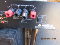
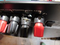
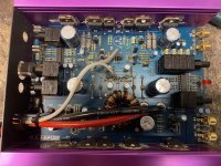
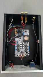
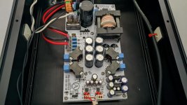
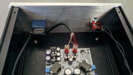
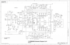
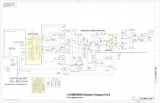
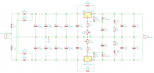
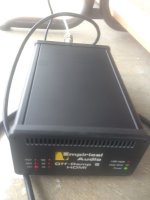
I have a QSC RMX 2450 amplifier that I bought with Channel 1 blown on ebay as a repair challenge. I finally got around to spending some time on it the other day, with mixed results:

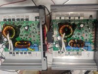
2x output transistors were blown on each side of CH1, as well as almost all the emitter resistors, one of the 22R B-E resistors on the negative side and the negative step driver FET as well. I replaced all the output transistors in the blown channel and the drivers for good measure, as well as the step driver FET. I was able to get the amplifier up and running and set the bias. Initial load tests looked good. I verified that the step drivers were working OK when the signal was big enough to need the higher-voltage rails. I connected a speaker and played some music, so far so good. However, a couple of gremlins remained.

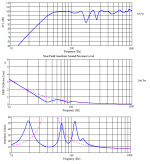
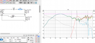
The first is that there is a slight thump in the speakers when it turns on. It is very slight, really not much, but it is noticeable. I thought the mute circuit was not being activated for long enough, however the manual says that approx 1 second muting is normal and I measured it as > 1second. Blue is negative rail, Yellow is one of the -15V opamp rails:

TEK0004.BMP


I am not sure why it still creates a bit of a thump, so I am open to some suggestions here.


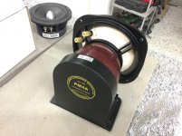
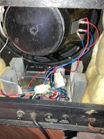
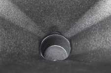
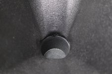
The second issue was the fan - it always runs, and it is a bit noisy. I assumed that the fan would be off until the amp warmed up enough to turn it on, but the circuit shows that it is always connected by at least 120R. I temporarily disconnected the cable from the Channel 2 PCBA to the AC PCBA and the fan ran a bit slower, so from this I know the optocoupler and the TIP31 are working OK - and the control circuitry on the Ch2 PCBA seemed to be working OK. With the amp off, the PTC on Ch1 reads 4-5 ohms higher than the one on Ch2 but other than that I could not find any anomalies with the circuit. It must just be a noisy fan, I will source a replacement.

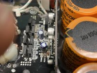
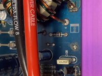
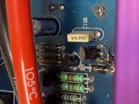
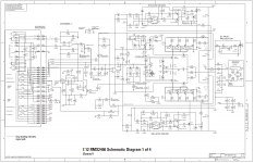
However, while probing around - I inadvertently created a short. I use long, insulated HV probes which only have about 1mm of exposed metal on the tips when probing a live amplifier, but in their wisdom, QSC placed an uncovered via directly beneath the leg of D13 and while I was probing D13, I shorted its anode to ground with the tip of my probe. As far as I can tell from the schematic, this has the effect of collapsing the -15V opamp rail on Ch2. The effect of this was a little horrifying - the output emitter resistors on Ch1 all went up in smoke.

Now, before I pull it apart and replace the blown transistors again, I am trying to work out why this happened. I could believe that maybe some DC was fed to the driver stage when the negative opamp rail collapsed, but Ch2 seems to still be intact whereas Ch1 is now blown. Why? The opamps have separate sets of rails for each channel. The amplifier was in bridge mono mode at the time, so I am assuming that the signal was somehow coupled this way into Ch1, but again, why did Ch1 go up in smoke and Ch2 did not? I never set the current limiting on Ch1 after replacing the output transistors as I had trouble finding a 1200W 2-ohm load with which to do it, could this possibly be why? I measured the resistance across the current limiting trim pots and they are quite different between the 'good' Ch2 (540R and 570R) and the blown Ch1 (800R and 420R).

The thing is, I bought the amp with Ch1 blown, so I am just wondering if there is something else I have not considered that is leaving Ch1 vulnerable in some way. I'd welcome any advice or suggestions.

Any observations or advice would be quite welcome!

Attachments

  • Ch1_schematic.png
    Ch1_schematic.png
    908.8 KB · Views: 915
  • Ch2_schematic.png
    Ch2_schematic.png
    768 KB · Views: 815
  • AC_board_schematic.png
    AC_board_schematic.png
    562.5 KB · Views: 840

B&W DM14 from 1980 - hot pics -

Hi,

Found that B&W DM14 on the side of the road. This sealed 2.5 ways made from chipboard two 18 cm polypro like cone and a 2.5 cm tweeter sounds a little boxy but I find the high mid and treble to be very nice. Quite heavy box assembled September 1980.

Shouted some pics of the drivers and the internal for Diyaudio archives:

1" (2.5cm) tweeter : TW26, 8 ohms soft dome, seems hand coated and is a little bright for a fabric dome. The dome is very soft at finger push but recover its shape back.

7.3" (18.5 cm) mid-bass x 2 : DW150/14 (14 ohms?) from the half of the surround it's a 5.76" (14.5 cm) polypro cone. back of the cone has a sort of wave a little like plastic coated paper but front cone suggest it's a full plastic cone. Not sure what the dust cover is : hard coated paper ? Surrounds are butylene, very light and thin... Speeder is weak, aging or born like that ? Qm should exhibit a high number. My ears are saying it has a good high mid and mid but not so a good bass. Perhaps the load, the drift value of the caps changing the crossover characteristics ? I can't say.

Not studied the filter yet. Lytic caps are PYE brand cap (the red 560 uF & 5 uF), some MKT or Mica (the browns) and mkp (10 uF) There is a little resistors network probably to supply the red led of the loudspeaker in the low left edge as it's not an active speaker and just mono wired.

Veneering varnish reacts to the methylated spirit. Enclosure has two U pieces of dense foam to line the walls and the top/ back. Full of stuffing, synthetic wool. Enclosure is 57 cm x 25,5 cm x 28 cm (deep)

Any thoughts or documents/links about this loudspeaker and/or drivers please ?

LM317/337 load regulation and ripple

Hi,

I have built a dual linear power supply based on the LM317/337 to provide +-12V from a toroid transformer.

If I connect to the positive rail a 10R resistor to the positive rail, the output voltage is 11.6V, if I connect a 15R resistor, the output voltage is 11.8V, for both in series, it is 12.0V (I have tuned the output voltage with those in series).

Does the LM317 really have this poor load regulation?

Further, when connecting both resistors in series (25R, i.e. 480 mA), I get an input ripple of 288mV, and an output ripple of 25mV.
Shouldn't that be much lower? The datasheet of my particular LM317 says 60-80db ripple rejection at 120Hz (I have 100Hz)

The schematic is attached.

Have I messed something up in the schematic?

Attachments

  • schematic.png
    schematic.png
    24.8 KB · Views: 675

OPA2134 Stability

My experience with the 2134 is that it doesn't like being used as a unity gain buffer. It is perfectly happy as a unity gain inverter (like in tone control circuits). I also used it in a non-inverting gain stage with a voltage gain of 1.4 with no problems.

I have successfully configured it as a unity gain buffer with a few extra parts (couple of resistors and ceramic capacitors).

I built a prototype of this circuit Project 99 - Subsonic Filter with op amp sockets. I tested three op amps in the circuit: NE5532, LM4562, and OPA2134.

NE5532 worked great but DC offset was 45 mV.

LM4562 worked great and DC offset was 3 mV 😎

OPA2134 oscillated. I tried using one 2134 and one 4562 and it oscillated.

To me, the 4562 should be the touchiest, with its 50 mHz GBP. But it seems that's not the case.

I have configured the 5532 as a follower with 0.1 to 0.2 mV DC offset, but obviously this isn't doable in a whole lot of circuits.

So has anyone else had a similar experience? I'm always looking for new tricks. 😉

Open Baffles with small exit Penetrations

Hello all,

Thinking of putting a little OB project together and cant help but ask regarding exit holes - see attached a la Emerald Physics - I would believe that the smaller exit is designed to "front load" the driver - but is it advised?

I admit, I am one LAZY SOB, and I have a 6" Hole Saw, and I hate using my jigsaw, as it always ends up looking like Stevie Wonder used it.

Application (with DCX2496) - pair of Eminence Alpha 15A mounted to front of 1-1/2" thick Baffle, or to backside with 6" exit hole...

Yes, No, or Hell No?

Go!

Attachments

  • cx.jpg
    cx.jpg
    169.3 KB · Views: 334

Bertagni speaker

I have studied these funny Bertagni speakers which consist of a magnet / voice coil and a polystyrene plate.
But I can not really figure out if the polystyrene is completely attached to the frame or if there is some kind of surround foam

Does the polystyrene move more at the voice coil than out at the edge of the frame?

I think it's a fun speaker and would love to try make something similar

1096124-e8f0cdb8-bertagni-electroacoustic-systems-bes-sm100-speakers.jpg


Video = (See 11:30 and 21:10 in the video)

Bertagni Electroacoustic Systems - Caixas de som planas (Plain Speaker Systems) - YouTube

Cheap DSP to learn about active multi-way speaker

I built a couple of DIY speakers (Quark and Speedster), and I really enjoy how much value you can get for not much money.

One day I'd like to build a bigger/better multi-way speaker using something like Hypex Fa123, but I have too much to learn before I start spending real money.

I was thinking of starting with something much cheaper to get into active crossover and active speaker designs, using a ADAU1701 board and cheap chip amplifiers.

I looked at some of the Sure offerings, e.g. WONDOM | STORE or even WONDOM | STORE which will allow to build a 2-way design with just a power supply. Or WONDOM | STORE for both speakers.

But I've read mixed feedback on the Sure modules, so I'm wondering if there are better boards I should consider. Any advice in how to get started is welcome

The Aleph 3Turbo: HotRodding the A3

There are about 5 things to consider when going for the evil twin of the Aleph 3. After the changes are made we will find that our A3s have specs similar to its older brother the Aleph 5. We get to keep the toasty DC bias of the A3 only toastier. I think this is what keeps the magic in the Aleph 3. Here’s how we can do it:

1. We need to have a beefier PS transformer. About 600-800VA; 2-28V secondary CT. This will deliver about +/-34Vdc loaded with the A3Turbo.

2. We need to increase the built-in current limiter’s current limit. As called in the A3 schematic, the limit is about 4Aac. We will increase this to about 5Aac. The limiter circuit is made up of Q104, R109 and R110. By lowering R110 to about 75Ù the current limit increases to about 5Aac. How it works: At lower load impedances, by virtue of Nelson Pass’s another paradox the Aleph dynamic constant current source, higher voltages and currents develop across and through the output devices and their Source resistors. At about 5Aac the voltage across R122 increases to about 2.35Vac. The voltage divider circuit that includes R109 will drop some of this voltage while about 0.6V develops across R110. 0.6V across the B-E of Q104 will be enough to turn it on limiting input currents to the Gates of the output MOSFETs thereby setting their output currents to a maximum of 5Aac.

3. For the positive going signal to keep up with the increase in negative going signal as the current limit was increased, the 66% of AC current gain (ACIG) as set by R114 will have to be increased. We will set the ACIG to about 78% by replacing R114 with about 634Ù of resistance. Both + and – signals will now start to distort almost at the same time.

4. If we are going to load up our A3Turbo with speakers that dip to 4Ù or 2 Ù at a bunch of frequencies in the audio band you might want to monitor your Source resistors if they heat up rapidly. We should replace them with a higher wattage ones if it did. Start with 5W.

5. As we did with the Source resistors, monitor our heatsinks. The touch and go method as explained by Mr. Pass is effective as it is.

Let’s fire it up. Oops! Nice output signal. That’s SIMetrix though. I’ve tried this at home but only on a computer. You can put into hardware if you find it appealing.

Please feel free to add to it if I'm missing something.


_____________

"For sounding good, I'll take the heat."

screen-drive (g2 driven) plate curves spacing linear!

Split from 6JN6 screen-drive (g2 driven) plate curves?

Hello, the voltage current transfer curve of a tube driven at a negative grid is non linear. The usual way to minimize the distortions caused by this non linearity is neagtive feedback and/or compensation of this non linearity, e.g. push pull. These methodes are used in solid state devices too. Thus the result is not much different. If you don't want these usual linearisation methods there is another option. The triode. It makes a self linearisation caused by the influence of the anode voltage in the electric field between cathode and grid. Same takes place in the so called "Ultralinear Circuit". It is the change of the g2 voltage that makes this influence. A positive grid ideally eliminates the influence of the following electrodes in the electric field surrounding the cathode. Thus a triode with positive grid voltage is getting more and more pentode like, the positiver the grid is. A pentode (and tetrode) driven at g2 is still a pentode because the g2 is positive and eliminates the influence of the anode in the electric field between cathode and g1. Thus the name "enhanced triode mode" is wrong here. There is a strong similarity between a bipolar transistor and a pentode driven at g2 and you can say it is a pentode in the bipolar mode. #16 All applications I have seen suffer with the problem that the voltage to current conversation at the positive g2 is still non linear. Some people accept this nonlinearity😉 and reduce it in the usual way as explained at the beginning. You can see this non linearity in the change of the spacing of the horizintal output curves of the pentode .#6 It is possible to make the g2 voltage drive linear and the spacing equal. #21 I'll explain this in the next post.🙂

Kind regards, Darius

Meridian 557 Power Protection Issue

I have a Meridian 557 that I bought new with a balanced Meridian stack around 1998 (502, 500, 566-24, 557) but it's refusing to power up now. It goes through the soft start sequence, stays on for a couple of seconds then you hear one of the protection relays click and it does a power down. I haven't been able to find a Meridian expert that knows their classic audio components in the Seattle area and the local "official Meridian support" folks are a home theater showroom/installation place that thought I was confused because they didn't know what a 557 was.

I had the local MacIntosh expert check it out for me (reluctantly) and he said the bias is too high on the right channel and that is what is causing the shutdown to trigger. He said it appears to have an auto bias system with no settings (does anyone know if that's true?). He was pretty impressed once he opened the top and said he could probably fix it but would need to see a schematic first. I have found a Meridian 556 schematic but no 557 schematic.

Has anyone seen an issue similar to this in the past and hopefully know what the cause is? I'm an EE/CS with some analog knowledge but I would not attempt to repair this myself. However, I can pass along any detailed information to Mr. MacIntosh who has 25+ years experience fixing high quality amps and other components.

Thanks,

Dean

Free (Australia) - two TPA3116 and one TPA3118 mono modules

Closed.... all gone.

Before I throw these in the bin, someone might be able to use these. Two TPA3116 mono modules (1 with volume pot and other without) and one TPA3118 mono module. All are working and are typical of most of these type with a bit of hiss and can have a turn on thump with some power supplies.

I'll cover postage in Australia and are supplied as a bundle only (all three).

Attachments

  • RZ_TPA3116_8.jpg
    RZ_TPA3116_8.jpg
    179.2 KB · Views: 119

Headphone jack+PC board NAD 1240

Hi all.

Forgive me if this is the wrong sub-forum...

I have a NAD 1240 preamp with a broken headphone jack. It is a solderable PCB-type, I believe the part # from the service manual is

L451Y017H01 PCB TYPE 9 PIN JACK HEADPHONE

This is the actual part that is broken (I stepped on something, lost balance and steadied myself on the first thing I found--the 1/4" heaphone plug sticking out of the preamp). Unfortunately, signal to power amplifier goes through this jack and the accompanying PC-board (# L241A066H12), so not good!

I doubt NAD stocks these, as I purchased the preamp new in 1987...

Does anyobody know where I can get a hold of such a phone jack? I can look for a similar vintage dead amp/preamp, but these are scarce here... Let me know. Cheers!

--Christian

Advice with my Series/Parallel extension cab puzzle

I want to connect my Polytone MiniBrute IV combo to a Polytone Pro Series Cabinet I found.

My question is, is my plan good, how to improve my plan? Thank you.

MY PLAN:
cut and resolder/shrinktube the 4 wires that make up the existing parallel circuit to the internal 15" and the EXT OUT jack, from that junction add a new pair of leads for the SERIES loop to the internal 15" and a NEW JACK w/SHUNT (1/4" switchcraft w/shunt). I will leave the HEADPHONE jack wired, but will stow it securely inside the box. The NEW JACK will go in the hole labeled HEADPHONE. I will add a label that says SERIES OUT.

I don't know why, move more air, fill out the tone, or just because it seems like these two old PTs belong together and there are some funk parties on the horizon

AMP:
Polytone 100w 3ohm
there's a single 15" 3ohm speaker in the combo.
"EXTENSION SPEAKER" jack [parallel to the 15" internal speaker] and some other jacks, I'm thinking of highjacking the HEADPHONES jack for an additional extension in SERIES (see below)

CABINET:
2 jacks
1st reads 8ohms - connected to a 8ohm 12" Eminence
2nd reads 4ohms - connected to a 4ohm 8" + 2x 8ohms tweeters​


Some calculations (courtesy geoffthegreygeek) show the most effecient (and safe) way to plug them all in would be to connect in:

SERIES the 15" 3ohm and Jack1 cluster (8" 4ohm +2tweeters in parallel 8ohm each = 4ohm) For 7ohms

and

PARALLEL the 12" 8ohm, 8ohms

My logic: this arrangement evenly distributs the power of the amp across all speakers, and the output Imp is 3.73 - only .73 over optimal


Is this a good idea?
Thank you

Attachments

  • IMG_2499.jpg
    IMG_2499.jpg
    979.6 KB · Views: 93

what do you use to fill gaps in waveguides/horns?

I have a pair of flange-mounted Eminence horns and a set of Dayton H6512 waveguides to compare sound for a 2-way speaker. I will mount both in a simple chipboard prototype box and see how they measure and sound to my ears before I advance to the final routed cabinet.

Despite the quality Eminence screw-on adapter EB 2 SA there is naturally a small but pronounced gap between the aluminum adapter and the waveguide's plastic. I made some pictures for you, the gap is only thin, but I think it has to be filled and also the plastic to be smoothed where it protrudes, for which a file can be used. But what do you use to fill/modify the surface of waveguides/horns? Here it should stick to the waveguide I think. Can you name some suggestions which I can buy preferably in Europe or give the technical term for a brand product which may only be available on your continent?

Regards

Attachments

  • IMG_1590.jpg
    IMG_1590.jpg
    729.5 KB · Views: 165
  • IMG_1591.jpg
    IMG_1591.jpg
    617.4 KB · Views: 174
  • IMG_1588.jpg
    IMG_1588.jpg
    847.4 KB · Views: 171
  • IMG_1587.jpg
    IMG_1587.jpg
    873.6 KB · Views: 170
  • IMG_1586.jpg
    IMG_1586.jpg
    810.5 KB · Views: 173
  • IMG_1585.jpg
    IMG_1585.jpg
    826 KB · Views: 74

ported guitar/bass cabinet design tools

I'm new here, so please correct me if this belongs in the software tools or live sound areas... I'm posting here because a ported guitar or bass cabinet is essentially a full-range speaker in that it's got one driver that you're trying to get the most of. It's just that the sonic end goal for a guitar cabinet is different from the Hi-Fi goal.

There are a lot of speaker cabinet calculators out there, but the ones I've seen all seem to assume you're trying to build a system for Hi-Fi. They don't seem flexible enough. Any recommendations for cabinet calculators (preferably web-based) that might offer enough flexibility for this application?

FWIW, I'm hoping to use a Jensen Mod5-30 driver that I happen to have on-hand.

Making a JMP 2204

Hello!

I need some help deciphering a schematic I found online for a JMP 2204. Plan use whatever applicable parts I have from my amp to make a combo. I have a decent electrical background and am starting to branch into sound/electronics.

1) From what I can understand, the blue resistors are variable, called potentiometers (volume, bass, treble, gain, etc.) I believe I got them all listed in this schematic. Am I correct in this understanding?

2) I'm new to speakers, and I thought the representation for them was straight forward, or maybe they aren't listed, but I used a pink circle for where I believe they would go on the schematic. Is this also correct? Or am I missing where they go?


3) At first, I believed the speakers to be what I highlighted as green. But then I believe I figured out that they are the diodes. Is this also correct?


These are my main 3 questions before I start looking more deeply into the diagram and construction. Any help you may provide would be greatly appreciated. I'm not looking for a perfect amp, by any means. Just one I can make myself as a project and save money. I currently only have SS and would like to upgrade on a budget on my free time.

Thank you!
Alex

Attachments

FS - Empirical Audio Off-Ramp 5 USB Audio Interface, S/PDIF Hynes Reg (Sydney, Aust.)

Item: Empirical Audio Off-Ramp 5 USB-Audio Interface, S/PDIF Hynes Reg, with BNC-BNC cable
Location: Sydney
Price: $1,750AUD + shipping
Item Condition: Excellent
Reason for selling: Not used
Payment Method: Pickup - Cash, Paypal

Extra Info:
One of the best USB-audio interfaces out there; pair it with a quality DAC.

I purchased this new from Empirical Audio in March 2014; it has spent most of its life sitting at my Mum's house gathering dust. It's as new; I'd estimate it has had way less than 50 hours of use. It has the S/PDIF Hynes Regulator upgrade and a very good BNC-BNC cable that Empirical Audio also supplied. It comes with a standard wall-wart power supply; I highly recommend pairing it with a high-quality power supply, it transforms the device into something even more spectacular. I can provide a 2-channel Keces PSU for an additional $AUD250 (purchased for $400), which is also in excellent condition with hardly any use.

At the current exchange rate, you'd be paying about $2675+shipping for the Off-Ramp 5 in this configuration (new).

Attachments

  • Offramp5.JPG
    Offramp5.JPG
    90.7 KB · Views: 191

Lots of new Mark Audio Fostex drivers for sale.

.F.S. New Mark Audio & Fostex drivers (Updated selling info).

Good morning everyone. I am cleaning house and I have a ton of new Mark Audio drivers and Fostex drivers for sale and a pair of ribbon tweeters new as well from fountek. I have most of the current mark audio drivers out today for sale. I have 2 of the fostex Fe sigma series for sale in some FF drivers for sale and a few Fe drivers for sale current drivers as well. Important note: the buyer pays all pay pal fee's and shipping. I will lower the price because of this. I can run the zip code to give you a price on the shipping?Again these are all brand new drivers never used still in the box just cleaning house. If the drivers are on sale at Madisound I will match the price. Please make offers and I will reach back to you. Please e.mail me at jeffmarch076@gmail.com for any questions and pictures. Thanks Jeff


These are the Fostex drivers I have for sale in pairs brand new.
1..FE83NV, FE103NV,FE126EN,FF85WK, FF225WK,FE108EZ, E208EZ + 1 for extra. I will give it away if you buy the pair of these drivers.
I have 3 Fountek 5" inch ribbon tweeters model Number #
$200.00 with shipping NEOCD.22 0M-BLK. I will give away the 3rd one if you buy them as a pair. I also have a Dayton Audio Mini Planner tweeter set as a pair for sale.
Mark Audio drivers I have for sale in brand new Pairs. 1, 6m in gold, 3.CHR 120 in gray, Pluvia 7phd, Pluvia 11 in gray, CHN 120 In gold, CHN 110 in gray, 7MS in Gold, , 11MS in gold, CHN 50 IN Gray, CHR 70a in Gray 2 pairs , CHP70A Natural paper, CHN-70, CHP-70A in black paper drives. The drivers I don't have in my possession to sell is;
The Alpair 12PW, 10 P, and 10 M from Mark Audio.


Thanks for looking. Jeff

Question about RH84 PS

I've spent days looking for an answer, but my dense head is just not grokking what must be dead simple for everyone else.

I'll be using a 5AR4 (GZ34) and the schematic shows a 5R4 with apparently six connections. I assume I'd wire AC into pins 4 and 6 on a GZ34, but I'm stumped on what comes out--maybe I use pins 2 and 8, with one of those connecting to the LC network and the other going to to the 5V section of the power transformer/rectifier?

Is this schematic showing a standard convention that "everybody" knows and that I've somehow never seen until now? 😕

by9SqLv.png


Reminds me of when I'm trying solve a chess problem and after a few good runs, I hit a problem that stumps me and in hindsight is dead simple. I can be blind that way sometimes. 😎

Speaker baffle recessed into cabinet, is it worth making it flush?

Hello,
some speakers (Kef 104, Concerto, etc.) do have the front baffle recessed into the cabinet to acommodate for grille frames. Would it be worth soundwise making the loudspeaker baffle flush with the border side panels? I wonder if it could help somewhat with imaging... I was thinking doing that to my Concerto kit speakers whose baffles are recessed about 1'5 cm into the cab
What do you think?
Thanks

Mei xing MC368-B150 amplifier

Ok I have acquired a mc368-b150 amplifier and have done a few things with it to share. I haven't really found a lot of info on it so I will start. First of all i ordered this amplifier from china to work with 120vac what i got was a 115/230v version with a 230v power cord but amp was set for 115 vac with appropriate fuse 5 amp. i contacted ming da via email and was told that it will work fine on the 123 vac i have at my receptacle at home. I have a yaqin mc100b that i run at exactly 110v with an apc voltage regulator as its rated 110v ac +/- 10% and 123 vac is out of its upper limit. ming da says the mc 386 b-150 amp i have actually has power transformer wound for 120vac with +/- 10%. I am currently running it at my house 123 vac power. so i open the amp and check a few things. first of all the bias of the amp was a little high so i rebiased the amp for my house power which by the way is suppose to be .4 to .45 vdc across the 10 ohm cathode resistor between ground and pin 8 of the KT150 tube. B+ is too high for my current fluke meter which is rated for 600 v it wont read it so im assuming its above 600v. the 6sn7 and 6sl7 voltages are within specs. and finally the heater voltage was sitting at 6.9v.the heater voltage is rectified via full wave bridge and filtered with large capacitor. so i added a .1 ohm resistor in series with the ac feeding the bridge rectifier and voltage is now 6.3 to 6.4 volts varies with load fluctuations.Also did some power testing using 2 200 watt 4 ohm dummy load resistors and feeding 400 hz signal into the amp with function generator. pushed the amp to signal just before clipping i calculate from rms value and dummy resistor right at 125 watts rms per channel not the 150 watts advertised but still pretty respectable amount of power. also linearity to the point of clipping looks good and balanced. all i have is a oscope and function generator so didn't do any distortion testing. Signal on oscope looked good didn't see any crossover distortion or ringing with a quick audio sweep of my function generator. OK now the sound what about how does it sound? well... I am running some jbl 2800 speakers and i use a fisher eq890 equalizer and at first the amp didn't have very detailed bass but sounded good even running it with flat input sounded decent. after about 3 days of running it and rebiasing it it has opened up and sounds pretty darn good. bass finally came in and even my daughter came out to my garage and said damn that sounds good. she never does that lol. I have pictures of the internals but not sure if i can post them yet as this is my first ever post. I am an electronics tech with a CET and was an electronics instructor for 8 years and have 30 years in. any questions please feel free to ask. as of now i'm not going to do any more with the amp but listen to it. i will post more info on it as it comes Thanks

Best 15" driver suited for high xover frequency?

Looking for a good low distortion 15" driver that will play clean up to a higher than usual xover point ie. 2.5k or so. This will be for a passive studio monitor type speaker that can do light PA duty as well - not wanting to use DSP for this. I have my heart set on the B&C DE250 driver on a JBL JRX/seos type waveguide and don't like the way it sounds at higher volume crossed under 2.5k, so that's why I'm wanting a better LF/midbass driver that will fit the design.

One of the usual culprits I've found are the Eminence 3015HO and B&C 15HPL76 neo drivers, but I was hoping there was something better out there. Most of the 12s and 15s have nasty cone breakup past 1.5k and require lots of xover trickery to flatten out and once you go through a large count of xover components, most of the sensitivity is lost. I'd like to not need more than basic BSC and a zobel other than the basic LP components on the woofer.

Your input is appreciated.

Stetsom EX3000EQ not powering up

I have a Stetsom EX3000EQ that just stopped playing today. No FETs or outputs blew or shorted, the music simply stopped and the blue Power LED started to flicker and die out and I quickly pulled the power wires to prevent further damage until I got to check it out.

Unable to find anything shorted inside, just not getting +12v at various points inside the amp to allow it to power up. The +5v regulator is only showing 2v on the leg that should have +12v so there is a power interruption somewhere. I have a working one open alongside this one for reference but I just haven't been able to figure out where the interruption is occurring.

I swapped the 5V6 diode(D7) that is in the remote turn on circuit but that component is not defective as the one from the non-working amp, works in the working amp.

Attachments

  • IMG_20201031_002520.jpg
    IMG_20201031_002520.jpg
    1,004.6 KB · Views: 400
  • IMG_20201031_002539.jpg
    IMG_20201031_002539.jpg
    900.5 KB · Views: 364

Sundown SA12 Aeroport box

Hello diyaudio folks! This is my first post here, so if this is the wrong place for this, please forgive me.
I currently have a Sundown SA12 wired to 1 ohm hooked up to a Sundown SAE1000DV2 @ 1000 watts in a box built to Sundown's website provided box plans. It's pretty much a big ol' square box. I'm planning on building a box with an aeroport for simplicity and a bit different shape to open up some trunk room. The plan so far per Torres...
Height: 14.5"
Width: 24"
Depth: 14.25"
Sub displacement: 0.14 cubes
Gross V: 2.16 cubes
Net V: 1.99 cubes
Port diameter: 3"
Port back/Sub back
Port length per Torres: 5.61"
Port length per WinISD: 6" (so let's say 5.75?)
Tuning: 35Hz

The question: Do those port dimensions look good or would one of you lovely people have a different suggestion on length/diameter/etc?

Converted my 26 Preamp/DAC to CX-301A - First Impressions

Although I've been extremely happy with my 26 preamp/DAC, the tweaking bug bit me again so I decided to try out some 01A tubes in place of the 26.
I picked up a nice NOS pair of CX-301A online and set out to make the modification.

It turned out to be much easier than I though it would be, as no modifications were needed to any of the power supplies or even to the biasing arrangement. The 26s were biased with 9V lithium batteries on the grid that actually put out 9.5V with no load (fed through the LL1676 input transformer secondary, so no DC blocking cap needed) and this turned out to be just right to bias the 01A at ~-4.8V given I am running the 01A filament at +4.7V using Coleman regulators. All I needed to do was adjust the plate CCS to 3mA, change R1 in the Coleman regulators to 4.4ohm from 1 ohm, and adjust the Coleman regulators. I soldered a pc-mount terminal block onto the Colemans to make resistor swapping easier in case the bug bit me again (picture 1). The output is taken from the mu output of the CCS to a Bent Audio remote controlled Slagleformer volume control in a lossy parafeed arrangement - the volume control has ~ 150H inductance. Silver wire on a nickel core. No problems driving anything to date.

A few pictures. The preamp as first built (picture 2). Topless shot with the new CX-301A tubes (picture 3). The Buffalo IIISE DAC and Sonore USB input boards are in the top right corner of the box. I have a switch on the back to go from DAC (SPDIF or USB) to preamp (5 line inputs).

So...how does it sound? I've been a staunch supporter of the 26 as a preamp tube, but my first impressions are that the 01A has it beat in terms of detail, air and that certain lush sound, without losing any of the punch or low end. Snare drum shots and massed horns are startling in their intensity. The 26 sounds a bit less precise and a little less "juicy" in comparison. More listening to come but I'm thinking it's going to be hard to go back to the 26 for quite a while...I may also need to get a new faceplate...Max01A maybe?? Or maybe I'll be non-committal and go with MaxDHT.

PS: Rod Coleman was his usual extremely helpful self when I peppered him with questions about his regs and the 01A. Thanks, Rod!

Attachments

  • Coleman Regulator with Terminal Block.jpg
    Coleman Regulator with Terminal Block.jpg
    321 KB · Views: 426
  • 26 Preamp and PS.jpg
    26 Preamp and PS.jpg
    341.3 KB · Views: 425
  • Preamp with 01A Top View.jpg
    Preamp with 01A Top View.jpg
    302.8 KB · Views: 413

Horn Folding Tips

I am new to audio Community, facinated about acoustic impedance maching devices AKA(horns) 🙂.

I am currently planning to build a FLH with vented chamber :smash:.

From some knowledge on reading tons of treads on horns, I know that the straight round horn is the best case scenario 😀. But horn gets very long therefore, folding.

So in folding horns, 90 degree bend better than 180 dergree ?.

Does 180 degree bends mess up air flow ?.

Does it creates higher order modes ?.

Causes unwanted turbulence ?.

I have never seen a FLH with 180 degree bend. But a 'TON' of tapped horn with 180 degree bends....
This is my first thread, And english is not my mother tongue. Please forgive me if there is any mistake 🙂. And feel free to correct me :cheers:.

kind regard🙂.

Advice for new speaker build

Hi All

I am a fairly new speaker builder with one project under my belt and I have decided to build another. I thought I would come here first to see if I could receive some advice. I am planning on building a portable Bluetooth speaker with the following components
Woofer: Dayton Audio DSA115-8 4" Designer Series Aluminum Cone Woofer
Tweeter: Dayton Audio ND16FA-4 5/8" Soft Dome Neodymium Tweeter 4 Ohm
Amp: Dayton Audio KAB-250v3 2x50W Class D Audio Amplifier Board with Bluetooth 4.0

I have also made a simple crossover design on Vituixcad2 with the data given from Dayton Audio. I will post a screen shot of the simulation below. Any help with this would be very much appreciated.

The tweeter is 4 ohms and the woofer is 8 ohms and the amp is rated for 4-8 ohms so does this work?

The tweeter also has a Power handling (RMS) of 30 Watts. The amp is 50 Watts. Do I need to worry about this after using a crossover?

Thanks in advance for any help!

Attachments

  • ammo 1st crossover design.PNG
    ammo 1st crossover design.PNG
    245.8 KB · Views: 89

Anyone familiar with philips Cd Control/Decoding systems? SAA7341

Anyone have a deep understanding of the philips CD control and decoding system? The SAA7341 Decoder IC?

I am trouble shooting a CD player that has a problem with the CD motor control. The CD spin's backwards and won't read a disc(i believe it does not have any PWM motor control). Looking at the Datasheet for the SAA7341 it is a bit cryptic on how it controls the PWM to the CD turntable motor. the datasheet reads as if it ONLY controls the motor on acceleration. but does not give any info if it controls the motor during play?

In the attached photo. pin 28 of the SAA7341 is the PWMA output that is connected to the MC68 Micro controller and the TCA0372 Power opamp that controls the turntable motor.

i am trying to understand the joint operation between the 7341 and the MC68 controllers. I believe one or the other is not putting out the PWM signal to control the motor. one or both IC's may have failed...OR...the problem might be further upstream. is there a Laser/focus/radial error causing a loss of PWM? how do i tell...etc

Is there anyone here that has a solid understanding of these old machines?? Please PM me.

Audio Inovations Alto (old) problem

I have this CD player (the older one with tuner) that has a strange problem.
Upon inserting a disc the sled moves to approx. middle portion of the disc and tries to read the TOC from there.... Of course without success, reading: No Disc. (laser works, lens servo works) I tried it with another mechanism (KSS213C) from a working player, but the problem remains. Any idea? No documentation (service manual) is available from anywhere.
There are no adjusting trimmer pots (focus, tracking,etc.) on the PCB....

Small neodymiums used as bucking magnets.

If I want to add some smaller neodymium magnets as bucking magnets on a midwoofer with a ferrite magnet, where would I place the neodyms, and with which polarity, to achieve the strongest field-increase in the airgap?

I know that a ferrite bucking magnet the same size as the original magnet should be attached just above the original magnet, with opposing field direction. So I guess I could attach the neodyms the same way, above the original magnet and with opposing field direction (they reject each other).

But maybe it would be better to place the small neodyms right at the center of the pole piece, with the same polarity (attracted to the pole piece), so that the field from the neodyms point directly up into the pole piece.

What do you think?

Vector Signal Analyzer VSA for diy audio....?

Hello All,

I enjoy the DIY Audio side of electronics and have access to an HP 89410a Vector Signal Analyzer. I see that it can make FR measurements, Phase Noise, Distortion and so many more. Would this be a useful bit of kit for my efforts building amplifiers, speakers and pre-amps? Or is it too cumbersome considering all of the great software available?

I do have an HP 8560E, TEK AA5001 & SG5010, and a 2465b. Would this 89410a be a good addition to the lab and if so what will it add to my current abilities to measure regarding DIY audio tinkering? It is in excellent condition and I would be disappointed to move it along and then find that is EXACTLY what I could have used for anything in my pursuits. But I do not need to simply collect gear for the sake of "cool tools" that are essentially duplicating any that I already have on the bench.

Cheers,

David
Projects by fanatics, for fanatics
Get answers and advice for everyone wanting to learn the art of audio.
Join the Community
507,930
Members
7,894,262
Messages

Filter

Forum Statistics

Threads
406,517
Messages
7,894,262
Members
507,930
Latest member
AquilaNaia