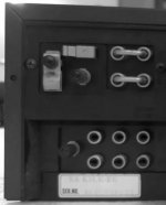
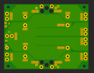
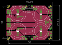
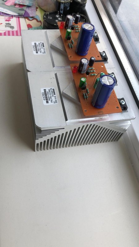
Digital Designs DM2500

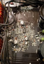
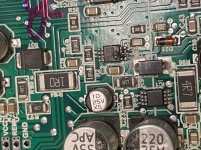
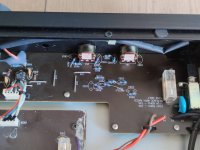
This amp had a shorted output and blown power supply.

I have installed four new outputs where the shorted one was.

I have installed new power supply drivers and 47 Ohm gate resistors.

Found R99 burned open and I could not read its value. One end connects to the main ground and the other connects to the secondary ground. I have installed a 0 Ohm resistor there.

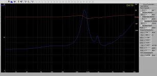
Amp goes into protection without power supply mosfets installed.
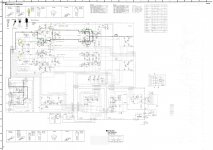
494

1) 0V
2) 5V
3) 4.457V
4) 0V
5) 1.483V Saw tooth is present
6) 3.62V
7) 0V
8) 14.3V
9) .034V
10) .034V
11) 14.3V
12) 14.3V
13) 5V
14) 5V
15) 2.046V
16) 3.911V

393

1) 5.132V
2) 5V
3) 8.135V
4) 0V
5) 2.581V
6) 2.111V
7) 5.132V
8) 14.3V

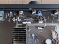
Taking Pin3 of the 494 to ground does force it to work and I have good drive to each gate pad.

I have checked each transistor for leakage and none are defective.

I could use a little help finding the fault on this one.

Attachments

  • 20210604_021745.jpg
    20210604_021745.jpg
    444.2 KB · Views: 213

Aurum Cantus G2Si replacement ribbon

I’m looking for G2Si replacement ribbons. I purchased a pair of speakers from a friend on the east coast. And the arrived with a damaged tweeter and driver. I was able to replace the drivers. But I cannot find new ribbons anywhere. So here is what I’m after.*
1: replacement ribbons (2min but 4 preferred)
2: info on wether I can trim the length off the G3 tweeter and use those ribbons (all specs minus length are same)
3: A pair of replacement tweeters if anyone has a pair for sale.
4 : a good alternative to this model

Thanks in advance!

*If the info is found elsewhere please direct me. I found nothing using the search tools. But that doesn’t mean anything considering my relative noob action on forums.

Some DIYSG measurements: HTM-12 V1 & Volt-6

Thought some of you my be interested in seeing some high-resolution measurements from my recent reviews. There is no way for me to effectively copy/paste all the text and images so I am just sharing the links below.


The HTM-12 v1 can be found here:
DIYSG HTM-12v1 Speaker Review

Note: The designer sent me the parts to upgrade to the v2 and that testing is now complete. Just needs to be analyzed and typed up.


Volt-6:
DIYSG Volt-6 Speaker Review


- Erin

DC offset ± 48V situation on Yamaha AX 750

Hello!

On the diagram below I checked as diodes all transistors Q619 ... Q643 and they are ok but I always have either -48V or + 48V starting with the collector of Q619 and up to the base of Q640 / 641.

Something escapes me, Any idea?

I attached measurements, I think the problem passes "through" the input (IC601A), at different restarts DC offset appears or -40V, or + 40V as I noted above, with orange I put the voltages when DC offset occurs "-", with green when it goes on "+".

The voltages are lower compared to the normal ones because I supplied them ballasted by 2 lamps 48V / 5W (they light up poorly) because Q635 or Q636 heat up one by one (Ubc = close to supply voltage due DC offset), depending on how it goes, on + or -.

Something seems irregular with the voltages on the IC601A inputs / outputs.

Somehow it is unclear to me the role of IC601A combined with (Q602 & Q603)

Attachments

  • service-yamaha_ax-750_sm_01-03-NJM corrected.jpg
    service-yamaha_ax-750_sm_01-03-NJM corrected.jpg
    937.8 KB · Views: 226

Mono amp for a centre channel

Hi there,
i have an unused mordaunt-short avant 905i centre channel which i would like use as a mono speaker for music (a diy homepod/echo...without AI)
I don't have any amp, i'm cheap so i searched something on aliexpress...what do you think about this TPA3116 mono amp? AIYIMA TPA3116 100W Subwoofer Amplificatore Audio TPA3116D2 Mono Amplificatori di Potenza Digitale Amplificador Con NE5532 OP AMP|Amplifier| - AliExpress
Is a good choice? Is there any better choice? It is sold as a "subwoofer" amplifier...is it true or is in reality an universal mono amp?
Is this a good idea or i'm completely wrong?

Thank you for your help!

P.S. i'm thinking to use an old laptop PSU for power.

project altec vot jbl 4560 style under hornresp

Hi everyone
This is my first post on this forum
I have the speakers: beyma sm115/n and jbl 2445.
So i m looking to do something with that.
I will make my self a arai 290.
I choose the sm115/n for his price, go low and high, just need big volume in bass reflex: around 200 liter.

But and this is why i write my first post here, i m look how to simulate something like VOT, and it look good on hornresp.

So in image
jgJLBh3

7YPS3W4

cFzR8XM

9pdC0C1

Gk3HqS0

HVVNT7R

XtsPB2V

3TszKKK

r43MBBb

pbfLXqc


Do you see something wrong ?
S1 92 is not to small ? from the simulation no but hornresp doesnt calcul air velocity first from port, second from the throat wich is smaller than the port...

What do you think about ?

SM115n
1MQgW08

VVLZfH7

z6j09SJ


The distortion go up under 55 hz that why i m thinking about something like VOT


Dimitri

DIY - Daughter's First Real HiFi

I have a wonderful 25 year old daughter who has finished college and grad school and is working in her first professional job (CPA). She appreciates music as much as I do (12 years of piano and band). She enjoys my setup and enthusiastically tells her friends (the few who are interested) about it. She has never had a stereo of her own and she's on a pretty tight budget. Like most young folks, she streams with earphones on the go, and listens through smart speakers at home. Bach's Cello Suites by YoYo Ma are her most played tracks –– because it's soothing and she can listen while working without being too distracted. But she likes a variety across many genres.

She deserves something nice for Christmas this year, and I believe it would be meaningful, in a way that may only be fully appreciated by a father and a daughter who connect through music, if I build her a decent hifi setup as my gift. I have built two amps from kits, and pretty much rebuilt my speakers, so I'm fairly confident with assembly and soldering and so forth. Here's what I'm thinking...

1. A good pair of bookshef/stand speakers from a kit with flatpack enclosure, probably two way. Decent bass response as I don't intend to do a sub right now. I'm not too worried about efficiency since the amp will probably have >100wpc.

2. A good quality Class D amp kit like Hypex or Purifi, stereo with volume control.

3. Raspberry Pi streamer, probably with a DAC HAT that can feed straight into the amp and she can control via her phone or computer.

I want great sound, of course, but I also want stuff that is durable, not fidgety or prone to needing attention. It could get cranked up at times, so I want the speakers to be able to handle what the amp dishes out. And I want it to look good, at least the speaker cabinets (I'll veneer, stain and seal).

I haven't done much research yet, so I'd appreciate ideas on which speakers and amps would be the best choices, and a low-cost DAC either mated to the RPi or stand alone (first thought is a HAT). What kits are proven and loved. My budget is around $1500 give or take a few hundred. Thanks for your thoughts and ideas.

My Documentary Feature @ Berlin International Filmfestival

I was not very active 2020 and 2021, the following link explans why😀
Maybe some members in or near Berlin are interested.
Ticket sales started yesterday, some tickets might be still available.
For North America, I hope my documetary will be shown in Toronto.
Best, Salar
| Berlinale | Programme | Programme - In Bewegung bleiben | Keep Moving

help with troubleshooting house electric

My house was built in the 50's copper wiring and a 100 amp panel. I have noticed lights flickering and not localized to one breaker. I have replaced 90% of the receptacles and switches, no change. I hooked up my Dmm and set to min, resulting in readings as low as 109v. While my utility was slow to respond, they ultimately replaced my service (pole to house) saying the neutral was not originally done correctly. still having the flickering issue. All of the lighting has been upgraded to leds, a few CFLs, Energy star appliances etc so the overall amperage is probably lower than ever. The breakers have not tripped, ever. As a thermographer, i understand how to use thermal imaging well and can see none of the breakers are near overload. Breakers that looked "hotter" were changed. Still have the dang flickering!!!

We are in the process of getting quotes for replacing the entire fuse panel and meter panel...


The electrician is not confident that the issue will be resolved, as he feels the same way I do. That low voltage shouldn't be an issue unless I was pulling serious amperage. And even then, still shouldn't be a problem.


Any ideas folks? Was thinking of trying to log the voltage for a few days directly off the meter... dunno..

Confused about LM1875 kit

There is a discrepancy in circuit diagram and PCB markings. If you look at the attached pics 10uf capacitor is wired - “minus” towards input source on the diagram but on PCB it is other way round. Which one is correct? I thought it should be like on PCB, + towards source?

Another question is there is 10 Ohm resistor from audio ground to actual ground, but all my preamps have actual ground as audio ground. This resistor will be redundant if I connect preamp. Why is it there and what happens if it is shorted?

Attachments

  • 1B27B4C2-1CE7-4F70-B076-915B8C002F78.jpeg
    1B27B4C2-1CE7-4F70-B076-915B8C002F78.jpeg
    98.4 KB · Views: 367
  • 029FF9B4-1A23-4779-AA82-B944EA3574E8.jpeg
    029FF9B4-1A23-4779-AA82-B944EA3574E8.jpeg
    116 KB · Views: 361
  • 80DF4B73-6B20-47B1-ACE3-528595B401B6.jpeg
    80DF4B73-6B20-47B1-ACE3-528595B401B6.jpeg
    83.8 KB · Views: 351

Soft-Start for Mercury Vapor Rectifiers With a TV Damper Diode Rectifier

I intend to add a 6AX4 damper diode in series with the plate supply rail to my DHT SET amplifiers. The graceful turn-on of the 6AX4 will of course provide a reasonably slow ramp-up of the high voltage as applied to the plates of the tubes, and will allow the mercury vapor (MV) rectifiers to warm-up before full load is placed upon them. This is a requirement when using MV rectifiers.

I have two options as to where I can locate the damper diode within the power supply circuit; within the + plate supply DC rail immediately after the MV rectifier tubes and before the filter choke (choke input filter configuration); or at the negative return of the power supply, that being between ground and the center-tap of the plate transformer.

I am of the opinion that locating the damper diode tube at either of these two locations within the circuit will make no difference in terms of it's intended purpose, that being a graceful and gradual soft-start of the high-voltage.

However, to be safe, is there a preferred or recommended location for the damper diode rectifier tube for my application? If so, why? There may be some subtlety associated with either of these two approaches that I may be overlooking, that could reduce the effectiveness of the circuit, or degrade the performance of the power supply.

WTB: Pair of Peerless 830875, SEAS CA18RNX or ER18RNX, Pair of SEAS 27TFFC Tweeters

Hello, I'm looking for the following drivers:

- SEAS CA18RLY
- Vifa D75MX-41 or the Scan-Speak D7608 equivalent
- SEAS 27TFFC
- A 10 or 12" TC Sounds LMS-4000 - red basket version

Singles and pairs considered. Used is fine, as long as they are in full working order and nice cosmetic condition.

I'm also looking for a fully functional Crown K1 power amplifier.

If you have any of the above, or know anyone who does, please let me know. Thanks!

Mount Aaustor NAS Folder on Daphile Music Server

I'm trying to mount a music folder onto my Daphile Music Server (Linux based).
I have created a folder volume1/Public/Media/Music.
I have created a user media and added ot to a mediausers group.
Both the group and user media have RW access to /Public.
I have enabled CIFS and NFS on the NAS.
I have setup an NFS share on the Public folder accessible from the IP of the Daphile server.
I have also set up CIFS share privelages on the same.
The settings in the Daphile UI I am using are similar to..
NFS://xxx.yyy.zzz.nnn:/volume1/Public/Media/Music
cifs://media@xxx.yyy.zzz.nnn:/volume1/Public/Media/Music with the user media's password in a seperate field.

Neither the NFS or the CIFS share is connecting.
Any ideas why please?
Regards
Clive

Soliciting Comments on 1st Time Build Layout

Hello--

Am toward the final stages of layout planning for a JE Labs Deluxe 2A3 build. This is my first "from scratch" build. While I am confident in some aspects of the layout, I am curious to hear from those who have experience in amplifier layout, especially with regard to lead dress.

The "tl;dr" here is this: Which wiring must I absolutely keep as far as possible from which other wiring, especially with regard to B+/plate, filament, and signal, and which are the ones which are more or less taken care of by proper braiding and routing?

I am struggling to choose between a layout which splits the L & R channels down the middle with a power supply section and a layout which devotes half of the chassis to the power supply, and the other half to handling of the signal.

Am also interested in first-hand experience with toroids and whether there are any general rules-of-the-road for their placement. From what I have seen in searches on the internet so far, the EMI put off by toroids seems to be negligible, and what is there is emitted out of the "hole" in the middle--i.e., elements above or below the toroid may experience interference, but not to the side.

Please see the attached photos before reading further. Obviously plenty of small components are missing from the layout. I have purposely included only the largest components.

For those familiar with the circuit, I have modified the power supply to be CLCLC.

The chassis is 10x17x3 aluminum from Hammond. The general idea is to segregate all the power supply elements to one side of the chassis. The speaker output and RCA input will be mounted vertically in the chassis to the rear of the output transformers (the white squares on my layout board). The signal input would be routed left to the corner, then down, then in front of the tubes.

Please ignore the pin count of the tubes. I still have some parts to order. There will be two sets of 3 tubes for the driver & output sections, then a single rectifier. Each 2A3 will have a coupling capacitor and a chassis resistor nearby, as shown for one.

The output transformers will be mounted on top of the chassis, along with the main (toroidal) power transformer. The power TX will favor the right and back corner. Toroidal filament transformer is directly below the main TX. To the left of the filament TX are a pair of Pete Millett's DC filament supply boards.

The two black capacitors are the driver supply; the blue 100/100uf capacitor will supply the B+ and feed the driver supply.

There are two chokes oriented vertically to the right of the rectifier tube. They can be seen in the chassis photo. They will be to the right of the rectifier tube.

My main concerns are with all of the wires that are bound to cross between the DC heater supply, the OPT, and from the AC filament supply (tap off the main TX) to the 6SN7 & 76s.

I don't have the wiring laid out because it's where I am the least confident. I have figured out how to braid solid-core wire with the help of a drill, and know that tight braiding is a best practice. I also have some shielded 18AWG wire that can be used.

If shielded wire is used, where would that be best? The (relatively) high-amperage filament supplies? The high-voltage B+?

Is shielded overkill when properly braided wire is employed?

Ground wire will run from RCA input to the tubes, then between the big black capacitors, terminating at the vertical terminal strip near the rectifier tube. This will also be running near/under/over all of the aforementioned wiring which I am concerned about. Will that be a problem?

A center layout would allow me to completely avoid all of this cross-wiring anxiety, but it would also be more cramped and results in a top-plate which I think would be less preferable aesthetically. (Forgive me!)

Is there anything I don't even know I should be thinking about but am not addressing?

Really appreciate any and all comments. Thank you!

Attachments

  • PXL_20210224_024320657.jpg
    PXL_20210224_024320657.jpg
    167.7 KB · Views: 226
  • PXL_20210224_025033620.jpg
    PXL_20210224_025033620.jpg
    221.1 KB · Views: 229

FS: Rohde & Schwartz UPV & Switcher

Rohde & Schwartz UVP analyzer with 8ch switcher.
Have allmost all available options installed: K0, K1, K4, K22, B1, B2, B41.
Low distortion generator, Jitter and interface test, digital audio interface, also i2s on the rear pannel.
Manuals and software on CD-rom.
verified against Audio precision Sys 2 cascade
located in Denmark, Europe. Open for bids over 10k EUR

regards
Kim

Attachments

  • 999825b1-ecc1-473d-b119-5184e70a5fd2.jpg
    999825b1-ecc1-473d-b119-5184e70a5fd2.jpg
    688.3 KB · Views: 122
  • 202d3f9a-c19c-4679-9fd9-defa30c4f3e5.jpg
    202d3f9a-c19c-4679-9fd9-defa30c4f3e5.jpg
    505.3 KB · Views: 132

Output impedance 6 ohms??

Triode 25 - Unison Research - Official Website

I know very little about valve amps and am considering buying one. I see this well reviewed amp has an output impedance of 6 ohms... Is this before or after the transformer? I can't fathom a damping factor that ranges from 0.7-1.5 for my various speakers.

Is output impedance usually specified? If so is it usually before or after a transformer?

Tweeter Amplifier Recommendation

Hey guys,

I want to switch to an active crossover ciruit and need your help choosing the right amp board. The crossover frequency will be around 1900Hz.

Current setup
  • 2x Dayton Audio RST28F-4
  • 2x Dayton Audio RS180S-8
  • 2x DiyAB Honeybadger
  • DIY DAC and preamp
My plan is to use the Honeybadgers to drive the Woofers and buy/build additional amps for the Tweeters.

Do you think it makes sense to use two extra Honeybadgers for the Tweeters or should i get another amp for them?
It would be nice to get a similar specced amp (apart from output power) that is smaller in size and/or cheaper to build.

Any recommendations are helpful and appreciated!

Cheers,
Martin

I "blew up" an Onkyo TX-NR709's amp playing with it

Am new to electronics and playing with them.

Which I suppose means I should anticipate "burned by the stove" type lessons lol

Well I was "burned by the stove" today and learned an important, however fundamental lesson today lol

Verify circuits prior to powering dut.

Just made a simple resistor bank to dump amp power into.

first iteration and testing went well. used an older amp and all went nearly as expected. issue being one of the resistors was getting hotter than the others.

The resistors are 8oh 100w and I thought I had them wired as 2s2p. However only by happenstance I had wired and connected them such that it actually only 8ohm 100w, the other three resistors in the bank were bypassed because of how I connected.

So anyways I redo the resistor circuit and am super confident is correct.

qFqny7F.jpg


I connect the speaker wire to the resistor bank(s) and amp outputs, toss on the input signal and turn up the power.....cue -20db or so and clicky pop poof and some smoke.

DOH!!!

This AVR was from my second ht setup. not intended to be the dut to practice / play with without care if it breaks.

So first examined it.
Thankfully, no visible damage. the power output transistors of JUST the left channel are both three way shorted. and one side of the dual emitter resistor is open.

I audited a few smaller components I believe are in the path and those checked out fine.

I ordered up the power transistors / dual resistor i'll find in some other amp am sure.


So onto what went terribly wrong.

To help my simple brain I put the circuit into a diagram. I knew which resistor bank was used for the left channel, the one confirmed that blew, right channel is fine. Immediately I thought I must have somehow* connected the left channel as a short.
such as imaged below. Absolutely plausible given the "mess" the resistor bank is.
tZ6U1uD.jpg


*But I absolutely recalled checking the ohms specifically as the amp would see, that is including the speaker wire; and BOTH channels were exact same 8.3 ohms (Bank is 8.0-8.1)

So, checked out how it was actually wired, and it was same as imaged next below.
csiGc7g.jpg


Only other thing I can think of is a strand of wire possible fell into the amp and some how shorted out just the left channel power transistors and emitter resistor.

So think it's most likely how I had the left channel connected to the resistor bank that caused it to fail.

The right channel was connected symmetrically, and it didn't blow out.

So is the resistor bank the left channel was connected to not correct? is it because of the yellow highlighted connection?

Also I suppose, since not experienced with resistor failure and especially of these values, perhaps they can measure fine with dmm but under load different story. Is that possible?

So far, while less dynamic an experience, I think 200$ in electronics education would have been better value here lol (here's hoping it will be fixed with the replacement power transistors and emitter resistor lol)


(I have quite an imagination; I envision a possibility is independent resistors not having same value. in that...
firstly, electricity likes to flow the path of least resistance.
the circuit, as the left channel is connected, depends on each paralleled sub-circuit's resistors be of nearly exact resistance. AND that that difference in resistance is more crucial the higher the power.
so in this case, perhaps the wiring of the left channel's resistor bank's sub-circuit with the yellow highlight is exacerbating any difference in resistance value.
And with that, the resistance was all wonky dependent on the power put through it....hmmmm I wonder lol

ESP P113 Compact Version

Hi guys, it's me again!

I decided, while waiting for my TPA3255 system to arrive (I tell myself I need to finish one project before ordering parts for a new one), to attempt to miniaturize ESP's P113 with some SMT parts and combine it with a PSU on the same board.

Gain has been set to 4.3 as per ESP's instructions as stock gain is way too high. All resistors are 1/4w 1206 except the 10R output resistors and the 0.1uF SMT caps are 0805 X7R. I also swapped the output transistors for MJE15032/33s. The PSU section uses two Meanwell IRM 15v units plus a CLC filter afterwards to get rid of the remaining noise, drawing inspiration from here. Middle hole is center of ground for the board and is meant to connect to chassis ground.

I uploaded the project to my GitHub here and the changelog can also be found there. Feedback would be appreciated as this is my first time laying out an amplifier. Thanks! 😀

An externally hosted image should be here but it was not working when we last tested it.

PCB_Traces.png

PCB_Top.png

PCB_Bottom.png

Render_Top.png

Render_Bottom.png

ESP P113 Modifications

I've changed the op amp to a OPA1652 and added a gain switch and now I'm thinking of decreasing the value of the emitter resistors and removing the negative feedback capacitor.
p113-f1.gif

I know that decreasing the emitter resistors too much leads to thermal runaway because it increases idle current, but how much can I decrease them by before that starts to be an issue?

As for the feedback capacitor, I simulated it in LTspice (5R emitters) and it appears to still be stable even without it.
yFmaGwO.png


Removing the gain resistor also appears to not trouble the circuit at all, so I plan to use two gain levels of x1 gain and x6.1 gain with a 5k1 resistor.
PYgJo3N.png


Are any of these things a bad idea? Please advise!

6N1P-V - 6Н1П Tubes

EMAIL]
Hi all

I’ve come across some 6N1P tubes described as 6N1P-V I believe they’re from the old Russian Reflektor factory. Does anyone know much about them? Interested how they would compare to the other 6N1P tubes.

An externally hosted image should be here but it was not working when we last tested it.

An externally hosted image should be here but it was not working when we last tested it.

An externally hosted image should be here but it was not working when we last tested it.

Importance of slew rate and transient response

Importance of driver slew rate and how to define it

An amplifier's speed is defined by the parameter "slew rate". It is measured in volts per microsecond. The figure varies from amp to amp, but for home audio amplifiers it usually ranges from about 10-100 volts per microsecond. Older amps are on the lower end of the range and are considered slower.

The higher the frequency that needs to be amplified, the higher the minimum slew rate must be.
The higher the amplitude of the highest frequency, the higher the minimum slew rate must be.

It's not enough to be only fast enough... For example, CDs sample rate is 2x the maximum reproduced frequency (disregarding filter). This is done to cover the 2 directions of movement in one cycle. It is not good enough for an amplifier to be able to raise and lower its voltage fast enough to match maximum frequency at the maximum amplitude. If a sine wave were applied to the input, the waveform on the output would be a triangle - not good. Amps slew rate should be at least 10x this amount to be considered acceptable. But the faster the better. Reaching the point when the waveform is not distorted is the goal. Amps don't have the advantage of CD players, which, when outputting their highest frequency, take 5 points and interpolate a sine wave (one of the reasons CDs sound unnatural).

If the slew rate is too low, lower frequency transients are too quiet and high frequencies are clipped to lower amplitude triangle-shaped versions of the input - it doesn't sound good.

I think a woofer's slew rate can be measured by applying tone bursts of increasing amplitude until compression unrelated to voice coil thermals results. Put another way, this is when the cone is lagging behind the signal because EM coupling is too weak. BI is a factor, but not the only one.

Things like BI, Mms, radiating area, frequency, and probably others would need to be used to calculate it. I don't know enough about the physics of it all to come up with exactly how, but if we could have a discussion about it, collaborate, we could come up with a new driver parameter which defines transient response. The higher its value, the more true to the input its output. Thoughts?

I think the frequency that is used should depend on the driver's size, cone diameter specifically. Since the measurement needs to stay away from xmax and beaming, I suggest wavelength 1.5x cone diameter. So 600hz for a 5 inch, 300hz for 10 inch, 200hz for 15 inch. This way up to 130db can be tested with 4mm xmax (basically every driver is compatible)
  • Thank You
Reactions: ginetto61

MiniDSP with resistor for Full Range with dual 18?

I am building a Lii 15 with dual 18s per side in open baffle. I would like to use a MiniDSP HD or DIRAC, but I am not sure if it is going to work. I think I will cross the 18s at about 100hz, and would like a subsonic limiter on them too. I think it would work better to have one 18 20-100hz and the other one 20-60hz. The 15 would take it from 100hz up.

My question / Could I do this with the MiniDSP 2x4 if I used a resistor to limit the one 18 to under 60hz? Would it cause issues with the measurements? Is there a better way to go here? Could I use 2 MiniDSP's? In that case, I would want to use the leftover 2 outs for a center channel. Could the unit manage controlling just the one 18 from L/R and also the Center?

I hope the questions are clear, and I would really appreciate any advice!

Using MJE1503X in place of TIP41C regulators for power supply

Hello, I’m repairing a Yamaha CR-2020 and performing the service bulletins. It recommends replacing the two regulators TR712 and TR715 as the originals get too hot. The recommendation is to use the TIP41C. I can place an order for them if needed, but I have a few dozen each of the MJE15032 and MJE15034 and would much prefer to use those if they’ll work or be even better.

Thoughts? Would it be better to use the 15032 or 15034, which of the two would be a better fit?

Dan

Any problem Using steel to mount driver by magnet?

Hey all. I’m wanting to not use m much wood in my next project (had to build too many shelves... need a break from wood) and was thinking of mainly using black steel plumbing pipe for an OB project.

Anyhow I was going to mount the drivers by the magnet by gluing them to pipe flanges but thought having a huge chunk of ferrous material right there might not be so great for the driver. You guys have any thoughts on this? Will it make a difference at all to driver performance? I’ll measure response in the process of doing the active crossover, so any bulk shifts in response are fine, just don’t want to introduce things I can’t correct for.

Thoughts?

Thanks!!

Audible hum - is it Power supply ripple?

I have a vintage Dynaco Stereo 400 that exhibits an annoying hum. It's only noticeable at quiescent (idle) and at low listening volumes. I don't know the frequency of the hum.

If I measure the power supply output, the rail is 150 volts DC with an AC component of 160 millivolts at 120 hertz. So the ripple is 0.106%.

Questions:
1) Is the magnitude of this ripple enough to cause the hum I'm hearing?

2) What is an acceptable level of ripple for an solid state audio amplifier?

3) If I replace the large capacitors, will this cure the hum?

Thank you all.

Gary

Measured phono signal levels

I measured the signal levels off some test discs.

My cartridge is Denon DL-103 specified 0.3 mV @1kHz @5cm/s

I use a SUT Lundahl LL1678 with 1:16 turns ratio. The reflected load is 47k / (16x16) = 180 ohms.
My preamp has about 50 dB gain @1kHz (a bit too high).

My first test disc (MHV - Hungarian Disc Co.) has a 80mm/s 1kHz reference track, where I measured 4.20 V output. This scales down to 2.63 V @5cm/s. Divided by the phono gain 315 gives 8.35mV. Divided by the SUT gain 16 gives about 0.5mV. This is much higher than the specified sensitivity of the Denon, which I don't understand yet.

Another disc I tested is the HFN&RR 300Hz "torture" tracks:

+12 dB - 6.19Vrms
+14 dB - 7.62Vrms
+16 dB - 9.40Vrms
+18 dB - 12.40Vrms

A good phono preamplifier must have at least that high overload margin. Multiply the above RMS by 1.4 to get the peak 17.5V, 35V peak-to-peak. With a more common phono gain 40dB this is relaxed by a factor of about 3, that is 12Vpp. Did you expect it?
  • Like
Reactions: hbtaudio

LT4320 CLoad Selection

Just for fun and my own personal education I thought I'd build my own LT4320 based rectifier for my test bench. Looking at the LT4320 manual it looks pretty straight forward. Just make sure you choose MOSFETs with a low RDS on and you're good. The only thing that has puzzled me a bit is the calculation of C Load. The manual seems to talk about C Load in thousands of uF when I've seen much lower values in other designs here. As a non-EE what am I missing?

Regards,
Dan :idea:

CLOAD SelectionA 1μF ceramic and a 10μF minimum electrolytic capacitor must be placed across the OUTP and OUTN pins with the 1μF ceramic placed as close to the LT4320 as possible. Downstream power needs and voltage ripple tolerance determine how much additional capacitance between OUTP and OUTN is required. CLOAD in the hundreds to thousands of microfarads is common.A good starting point is selecting CLOAD such that:CLOAD ≥ IAVG/(VRIPPLE • 2 • Freq)where IAVG is the average output load current, VRIPPLE is the maximum tolerable output ripple voltage, and Freq is the frequency of the input AC source. For example, in a 60Hz, 24VAC application where the load current is 1A and the tolerable ripple is 15V, choose CLOAD ≥ 1A/(15V • 2 • 60Hz) = 556μF.CLOAD must also be selected so that the rectified output voltage, OUTP-OUTN, must be within the LT4320/LT4320-1 specified OUTP voltage range.

Technics SA-K5L info

I got an old Technics amp with an interesting "direct drive" turntable from a friend, fully working, nothing special.
On the rear it got an "external unit" input and output that is linked out, what is that for?

If I remove the links, there are hardly any sound, not even on the headphones.

Attachments

  • rear.jpg
    rear.jpg
    11.1 KB · Views: 80
  • rear1.jpg
    rear1.jpg
    14.4 KB · Views: 77

Chris's "Teeny tiny PA 15" sub (Horn) - Final Version?

I’m still looking for the best choice in a portable (1-man carry) sub, that can handle DJ gigs as well as rock bands. IMO, the QSC KW181’s suck donkey balls.
The BR dual 12’s I just bought are absurdly bad when pushed, and not nearly efficient enough.

After going around in massive circles, I've actually come around to considering passive, horn-loaded subs. It's far from what I want in many ways, but it might in fact be the best compromise.

I've been looking at the Danley THMini15. I could probably handle a pair of those, but I'm a bit hung up at the -3dB @ 50Hz rating. I know folks love those boxes, and maybe that’s deep enough, but it scares me without actually hearing them.

The JT Growler looks really good. Flat to about 40 Hz, but they don't make them any longer. Also, the thought of just two 12” drivers handling all my LF is REALLY scary.
that just doesn’t seem possible. Still, that might be a design to shoot for, yes?
=================================================

### SO:

I have to also consider Chris’ “Teeny tiny PA 15" subwoofer.” From the looks of the thing, I could manage for of them in my pickup truck, which is lovely.

- BUT WHAT ARE THE SPECS? - Size, weight, freq response, maximum sustained output? Power required to reach that max output?

I looked at the original thread for this design, but it’s over 100 pages long. You gotta’ be kidding me… I assume the design went through some changes along the way.

Chris, can you give me a simple update, regarding the final version?
(Construction, and specs.)
--------------------------------


Also: Can anyone who’s used these give there opinion on sound, output, and how they work in various contexts?

The thing is, Maybe I won't like the "clean" sound of a horn, anyway?

I've read that the distortion generated by BR designs actually makes them seem louder, and I need a s much volume per watt as possible. - I have both a rock band & a DJ service, and need to use the same rig for both. (And need to carry it all myself. And need to tun on one 15a service, including lights... You know the deal. )

Has anyone used Chris’ design for DJ applications?

Orion amp

I know that people have mentioned using film caps as a replacement.

I do not have that much room in this amp to mount 6 caps on end

These are the 10uf 250volt bipolar caps .

I can get 10uf 100 volt bipolar caps locally .

Wondering would the 100volt caps work or are they very likely not to survive?

Or can I use 2 polarized caps and make a bipolar cap ? Say use 2 22uf caps connect the negatives together and solder in both positives to the board ?

Attachments

  • 049A4612-1253-4F19-A4BF-0D60F3D435F4.jpg
    049A4612-1253-4F19-A4BF-0D60F3D435F4.jpg
    991.1 KB · Views: 98

Old Soul/Old Soul Bip Kit packages

Presenting thread here: Old Soul


Schematic and pcb screenshot post #1 , plenty of pictures after .

Tips and Tricks thread - will open, sooner or later

Reading entire thread is advisable , same as inquiring any technical question there : Be sure that you are aware of all things electrical and mechanical !

Germanium thingies- still available on fleabay or here and there; I have some 2N1099 and 1T813, will try to obtain 1T813 in quantity, in time
Taking these from me - matter of arrangement via correspondence, what I have is going to be tested, in any case and only in that way I can send them with kit
Anyhow - Old Soul Bip ( SI Bigun instead of Ge one) is equally interesting and worthy toy


Pcbs are made for UMS , mounting directly to heatsink


Do not hurry - read , think , ask and only when you feel that you want it and can make it , proceed ...... advice which I'm finding applicable on practically anything .

For anything else , write either here , send PM or directly to >zenmodiyaudio@gmail.com<

Prices are mostly dictated with small scale nature of operation (as always is case) and time/work involved in matching and soldering little buggers.

For ordering , contact me at above written e-mail addy .


Kit options :

Option 1.
- LCH pcb ,
- RCH pcb ,
- all smd buffer JFets (Toshiba 2SK2145BL) presoldered ,
- smd precision CCS chips presoldered
- all smd caps and resistors presoldered ,
- 4pcs of 1uF MKC caps (for important bypass positions) enclosed.

Full price , including Paypal fee and P&P for registered shipping all around the Globe - 135E

Option 2.
- LCH pcb ,
- RCH pcb ,
- all smd buffer JFets (Toshiba 2SK2145BL) presoldered ,
- smd precision CCS chips presoldered
- all smd caps and resistors presoldered ,
- 4pcs of 1uF MKC caps (for important bypass positions) enclosed.
-all multiturn trimpots
-output N channel mosfets , 2 pcs , IRFP240
-cascode bjts
-optocouplers
-all electrolytic caps (all Panasonics ,except Elna Silmic II for one signal route position)
-one-pin sockets for special resistor positions
-all (MF 600mW) resistors
-T0220 heatsinks - 4pcs
-etc.

to recapitulate - everything what goes on pcbs , excluding signal xformers and pcb/mosfet mounting screws/nuts/washers ; again - Ge being matter of arrangement

Full price , including Paypal fee and P&P for registered shipping all around the Globe - 185E


If I have everything in drawers in moment of order , can ship in a week time;
If I don't have any of normal parts in drawer , shipping could be delayed up to 3 days;
If I don't have pcbs in drawer , shipping could be delayed up to 2 weeks;
If I don't have most critical part for getting in my neck of wood - CCS precision chips , shipping could be delayed up to 3 weeks.
All in all - you all know that ZM is slow, but inevitable

Handy Addendum (in short : HA!):

-Cap Bank pcbs - set of 2pcs; dual rail, CRC (pads, if you want differential CLC), snap-in up to 35mm Dia, resistor and pads for LED, position for 10mm NTC connecting Audio GND to chassis;
-NTC pcb/ FW style Soft Start - set of 2pcs; each having place for 2 independent NTCs;depending of arrangement of primaries of Donuts you're using. you'll need either one pcb for two Donuts, or one pcb per Donut

HA! set is 25E more

see pics for HA!; lazy to search do I have photo of NTC pcb, but who cares

Attachments

  • PSU pcb bottom.jpg
    PSU pcb bottom.jpg
    58.1 KB · Views: 589
  • PSU pcb top.jpg
    PSU pcb top.jpg
    86.1 KB · Views: 595
  • CB bottom render.png
    CB bottom render.png
    88.7 KB · Views: 595
  • CB top render.png
    CB top render.png
    160.1 KB · Views: 578
  • CB top eagle sshot.png
    CB top eagle sshot.png
    54 KB · Views: 577
  • eagle sshot.png
    eagle sshot.png
    17.4 KB · Views: 165
  • bottom render.png
    bottom render.png
    18.5 KB · Views: 164
  • top render.png
    top render.png
    38.4 KB · Views: 169

Identifying mystery valves using manufacturing ID code e.g. Xf4 = EL34

Hi folks,

I have a number of tubes that I cannot identify because the main print has warn off, but I can see the manufacture valve ID and date codes. These are Mullard valves (mostly radio/TV) that I found really cheap.

This as been useful for identifying dates MULLARD VALVE ETCHED CODES - HOW TO INTERPRET THEM – MULLARD MAGIC

I'm looking for a list of codes which matches the manufacture ID to the valve model number.

For example, these are given in the above post. But I cannot find a general list with 100s of codes anywhere!

Xf2 represents an EL34

k61 represents an ECC82

f32 represented a GZ34

Attachments

  • CODZ2_large.jpeg
    CODZ2_large.jpeg
    15.4 KB · Views: 292
  • Like
Reactions: decramer

loudness on/off control for SE KT88 amp

Im searching for some good shematic for loudness control.
And yes,i know that part of HIFI world is against loudness control,BUT,when you have small kids,and lots of job trough the day,and listen music at night at low volume,your ears desperatly want more bass and more highs.
So,i want to instal a switch-controled loudness option to my integrated SE KT88 amp.
Any sugestion for shematic?
Thanks!

Tone control PCB without capacitors in Cambridge Audio A1 mk3

Hi,
just curious if someone seen the tone control (Bass, Treble) circuit without capacitors? When opened for fixing Cambridge Audio A1 mk3 I could not believe what I saw...
Did CA invented new tone control circuit which does not require 2 pairs of capacitors and resistors for bass and the same for treble?

Kes

Attachments

  • IMG_20210405_165900.jpg
    IMG_20210405_165900.jpg
    678.5 KB · Views: 356
  • IMG_20210405_165910.jpg
    IMG_20210405_165910.jpg
    744.2 KB · Views: 360
  • IMG_20210405_165930.jpg
    IMG_20210405_165930.jpg
    644.4 KB · Views: 307

Regulated DC heater supply

Simple question. What would you use for a basic regulated DC heater supply? Right now I need about 2.5A at 4v but it would be good to have some general ideas.

AC isn't possible since I'm using dropper resistors from a 6v transformer and possible tubes to be used are 4v but have different currents, so the dropper resistors give different results.

I assume an LM338 is a simple solution. Do you need the input and output caps in the attached circuit, or could it be simplified if supply caps are inside 6" (says so in the data)? I'd be using a 6v transformer.

Using online calculators, with a 240R in R1 looks like you need 520R in R2 for 4v. Not sure what wattage though.

Suggestions for a heat sink size for 2.5A out?

Attachments

  • LM338 circuit.png
    LM338 circuit.png
    9.6 KB · Views: 408

TDA7294 Power Amp, 120Wrms

This is my first post!!
Thank you all in diyaudio, many times you've solved my questions. Now it's my time to post mine here.

So I'm trying to make a modular preamp and power amp, the preamp cranked up outputs 1.1V peak (0dbu), and I want to make this signal to go 120Wrms (8 Ohms) using some power amp IC (I've chosen the TDA7294 cause I kinda know its datasheet but if you like another one better, tell me!)

I've made my research and I think that making a brigde setup +/-24Vcc, 40 linear gain, 29dB ,I should be able to get to this level. But what if I use the FX return? Then I could go much higher and then I risk blowing up my speakers.

Can anyone give me some advice? Thank you all in advance

ps. Cabinet I plan on using: Harley Benton G212 Vintage Vertical – Thomann Espana

Help chosing budget DAC

Hi all,

I need some help with buying a budget DAC for aprox 200$ as replacement to soundcard.


First, i plan on using it to connect it to a tube amp. Lineout will be RCA interconnect.

Source will be a PC. MP3/FLAC/DSD and YT


For other features, i really dont care, focus is on sound quality.
Maybeee i will connect headphones to it, but its not a priority.


My choices are boiling down to following models.

1. Audioengine D1
2. FiiO K5 PRO
3. Topping E30


I do like first two options, anyone had some experience with them ?

Today's stupid question: AC+DC Programmable power supply?

Today's stupid question.

I know I can find a uber expensive programmable AC+DC capable power supplies. I just take my $4-6 grand in cash and throw it at a few companies and out pops a nice piece of lab gear. Not happening any time soon.

Not just any unit, either. Something in the ~+2-3 kilowatt range of output.

We know that high power class d sub amplifiers are around for peanuts in cost. even ones that can go up to about +1khz sine, and be about 1500 watts into a 1 ohm load, are available for under $200.

But it needs to be able to do DC at the same time, if required. I know I've got a (potentially) bridgeable but definitely DC capable power MOS-FET amplifier here (literally DC to about 100khz), but I'm not sure I want to stress it and take a chance on it going boom. It's a nice amp!

so, anyone aware of what might fit the bill? Stuffing a few boards is certainly not a challenge, and far preferable than the huge cash outlay. I've got many methods of getting power to such a circuit or board set, so that's not a big deal. I've got a few SMPS 80 amp/12vdc power supplies that can be paralleled, and so on. Meaning, modding a car amp that is suitable to the task at hand.

This is not my wheelhouse, for the most part. I can fake it like the bear dancing, but no tests at the end of the day....thanks...

Realistically, the back end can be a modded out power amplifier of suitable build and capacity, possibly with custom power supply. the front end can be a programmable signal generator. I'm looking or functionality at this time and I'm not too worried about losses.

ie, modded car amp, if one can actually do DC with enough power and efficiency and not catch on fire.....and then a set of SMPS based parallel 12vdc power supplies adjusted up to about 13 VDC (they have sense capacity for sharing, IIRC-- they are 1kw Dell server units)...and then a programmable siggie at the front, with a smattering of metering thrown in for good measure. IF class D amps can be made to do DC, and I'm sure it depends on the individual design..if so, then the whole thing is quite doable with other resources I have in hand. I'd just need to procedure the specific class D amp to beef up and mod out..

Lets just say I'm ignorant about one particular part of the question I'm asking. whether or not class D amplifiers can handle DC output as a norm or in exceptional cases with specific designs, or not..

Since it is about avoiding DC at all costs in audio amplification, one seldom sees any DC ability mentioned, as in never. As in no data, not even in the fine print. What idiot would want DC? (I raises my hand...)

But someone must have some understanding of this aspect ...and I don't want to spend two weeks or even two days.. digging through all the available data to find what I'm looking for. Which is a simple declaration, or clarity.... on what class D can do in the DC+AC department. I strongly suspect Class D is fine with DC but the audio package involved must be beefed up in some specific ways, if it is to be high power class D, and that any controller chips (front end) must also be DC capable and so on. Just a guess. Seems reasonable.

Any ideas?

Class D with GaN FETs & IC PE29102 (GaN FET) driver

Hello

Class D Audio Using the PE29102 driver IC

here reference design

https://www.psemi.com/pdf/app_notes/an72.pdf

Class-D Audio Amplifiers


GaN FETs Devices for audio applications. coming in the market.

GaN FETs are preferred as the switching devices because they offer significant advantages over
MOSFETs. Because GaN FETs are faster, smaller and do not have a body diode, they have fewer switching
losses versus conduction losses, resulting in superior linearity and efficiency


Does somebody already have expereince ?

XO cap recommendations

I'm working on a mono WAW system with a Scanspeak 10F8418G10 in a 1.2L sealed enclosure covering about 150Hz and up and a TB W6-223S run by a plate amp doing bass duty. While I'm generally pleased with the sound at the normal 80-85dB listening level, I'm wondering if a 200uf cap would let the 10F perform even better.
The problem is space - finding room for such a film cap may not be possible. Does anybody have a recommendation of an electrolytic that wouldn't be an insult to this special little driver?
TIA, Karl

passive current line

Hello everybody.
I would like to know from the experts if it is possible to realize the following thing and what problems or advantages it entails.
current DAC output stage instead of the I / V converter, immediately following the passive line crossover filter driven by current instead of voltage, then current-current power amplifier and finally speakers which are consequently current driven. Starting from the DAC output, everything is driven in current.
bye thank you

Ibanez Tone Blaster 25R Amp Solid State

Picked one of these up for $10 that needed the input jack repaired, figured the box and
chassis would be worth it for a cheap tube build.
The front panel layout is good for a rebuild with a clean and overdrive channel, bass, mid,
and treble controls and a reverb control. There is a small reverb tank mounted to the chassis.
It has a very cheap looking 10" speaker, at least it is a decent size.
The baffle board is 11.5" tall and I think that if a notch were cut for the frame of a 12"
speaker might drop in and then fit - not sure. I strongly prefer a 12".

Fixing it stock for now. Turned out the PC board was cracked right at the input jack, so I
bridged the cracks with buss wire which fixed the amp - it works!

Pair of 3300uF/50V caps in the power supply, TIP41/42 (6A, 65W) output transistors that
are too small in my opinion. Many JRC4558 OP amps.

The clean channel seems weak with the tone knobs at 5, turning the mid and treble up to
8 helps a lot with volume. The reverb seems very weak with the guitar signal but bumping
the case makes a crash from the springs. Reverb tank says 2K input and 2.2K output Z.
Must be difficult to get enough drive from tiny OP amps. Perhaps it needs a recap?
Overdrive channel is very loud.

I've been working on several small SS practice amps and prefer a Fender and two Peavey's
that I have. But the chassis should work fine for a tube rebuild, perhaps even use the
reverb spring.

Anyone know if the weak clean channel and reverb are typical of this amp?

Anyone have a schematic?

Online course for Speaker and Crossover design

I discovered this series of Speaker Design courses on Udemy recently.
I’ve read many books on loudspeakers, and built half a dozen kits from experienced designers, and recently did my own design with the Purifi midwoofer.

I wish someone had done this 20 years ago when I got started… this covers theory and practice, with a discussion of pros/cons of doing things.

Big ups to Marcus for creating and sharing such useful video content and step by step process to actually building your first 2 or 3 way speaker.

For the price of just a pair of tweeters:

Cabinet selection and design-
Acoustics 101 : Speaker design basics and enclosure design | Udemy

How to take measurements-
Acoustics 201 : Loudspeaker measurements | Udemy

How to design crossovers passive crossovers-
Loudspeaker engineering : How to design speaker crossovers | Udemy

Highly recommended!!

buying a heat air gun.

Hi there

I have bought a heat air gun for soldering, beause it needs to be not expensive and good quality I did buy this one on photo.

It is very good quality and it heats very well, I remove a chip very fast and easy.

worth by it, I think it is almost as good as a professional like hakko.

I need because in winter I go start build something.

Ohh yes for etching and using negative film, here some nice read stuff, a simple withener find here or in supermarket do work as a developer.

OxiClean - OxiClean™ White Revive™ Powder

read pdf also.

https://sparks.gogo.co.nz/dry-film-tips.pdf

regards


regards

Attachments

  • aoyue_852.jpg
    aoyue_852.jpg
    96.7 KB · Views: 292

DIY xover mess by previous owner - can anyone explain this?

hello to all

I purchased a pair of 3 way SD OBS speakers. ( midrange open baffle , ported bass )

seems a previous owner has removed the original xover, and simply fitted;

see photo attatched

1 x 2.2uF cap to the ribbon tweeter. ( 9khz xover )

Cap ( 126uF ) + 4.7 Resistor in series directly to the mid

nothing at all on the bass driver

I dont understand the cap + resistor in series, as for for a simple RC filter, the cap should go across the drive unit.


there are actually 2 caps in parallel, 112 and 14uF , connected to the resistor 4.7 then straight to the mid driver.

these 112uF poly caps are pretty expensive at £ 50 each, I mention this, as Im curious why someone would buy such expensive caps and then create this incorrect xover?

I have seen the xover circuit diagram for the SD1 model, ( larger non open baffle version of the OBS ) and was wondering if I could use that on my speakers.... I know theyre not identical, but Id imagine cant be worse that what Ive got already?

[ the drivers are:- Monicor RBT-180 ribbon tweeter , Dynaudio 5.25" mid ( dont know the model / no labels ) Audax 6.5" paper cone woofer ( dont know the model )

any help greatly appreciated

Attachments

  • SD OBS xover diy.jpg
    SD OBS xover diy.jpg
    462.7 KB · Views: 405
  • low pass RC filter.png
    low pass RC filter.png
    42.6 KB · Views: 563
  • Sd-Acoustics-Obs-Mk11-Speakers.jpg
    Sd-Acoustics-Obs-Mk11-Speakers.jpg
    20.9 KB · Views: 471

$5USD dome tweeter, diamond in the rough?

Any comments? measures +/- 1.5db from 2.5K

https://au.element14.com/mcm-audio-...ome-tweeter-30w-rms/dp/2827683?st=mcm tweeter


Seems ok to me, on par with $20+ domes... has ferro fluid


Not sure on that second bump in the zma

Attachments

  • mcm dome.jpg
    mcm dome.jpg
    190.3 KB · Views: 220
  • mcm dome xover.JPG
    mcm dome xover.JPG
    41.9 KB · Views: 214
  • IMG_3117.JPG
    IMG_3117.JPG
    307.5 KB · Views: 222
  • mcm dome zma.JPG
    mcm dome zma.JPG
    92.9 KB · Views: 215

Which chip amp can play sweet sound, need your experience

Hi friends

I want to build an active crossover sound system with chip amp for my living room. I know others discrete or tube amp sounds better then chip amp but chip amp is easy to build and compact and some chip amp sounds really good.I am puzzling :hypno2:to select by which chip amp i can starting.😕 I have already in my junk box LM3886, LM1876,TDA2009A,or i can manage any part no.

PPI Powerclass PC2350 (Grey) H-Bridge issue?

I have a prestine show-car condition amp on my bench for a customer. This amp is of course using SG3525 with HIP4081 in H-Bridge.

It won't power up. The current draw is 0.1A.

The SG is putting out clean drive on pins 11 and 14:
Just for good measure;
SG3525
1: 0.139
2: 2.585
3: 0.022
4: 0.176
5: 2.067
6: 3.783
7: 2.062
8: 4.92
9: 6.04
10: 0.002
11: 5.77 (Square wave)
12: 0.002 (GND)
13: 13.41
14: 5.74 (Square wave)
15: 13.41
16: 5.19

No BJTs/FETs are measuring shorted. Board looks perfect. Hesitant to remove it from the sync atm.

Absolutely zero drive at the PS fets.
Should I measure the pins of the HIP4081? Another component? Or is this amp a 'bust'?

Octopart search for HIP4081: HIP4081 | Octopart

Help with Goodmans Axiom 300s

I have purchased two Axiom 300s that look like they have good cones but the paper surround is ripping along the ripples in the surround. It has been repaired poorly before I purchased them and the repairs are failing.

I was thinking about reconing them but cannot find a cone worth using that would be considered a Full range cone.

The original design is a curvelinear cone that is over 3.25 inches high from VC to edge and is lightweight along with an aluminium wire VC. All recone kits available are heavier like the Celestion cones.

Does anyone have any suggestions about whether to recone or replace the surround and where to obtain the impossible dream.

Thanks in Anticipation.

Thoughts on Acoust X?

Hi all,

I've lurked in the forum but this is my first time posting. I searched around for info on this stuff but didn't find anything - if there's something I've missed, please let me know.

I'm in the process of modding my Zu Omen Dirty Weekends mkII. I've braced the cabinet near the drivers with dowels and will eventually upgrade the drivers with the Zu 103s and the tweeters with some Radian 475s. I've seen some folks recommend coating the inside of the cabinets with something like Acoust X. I was curious if that delivers a noticeable change. There's already foam bricks directly behind the drivers, so I'm not sure if adding a coating of dampening material besides that will make a huge difference. Thoughts?

Thank you.

Eton 3-way crossover REDESIGN - need advice

Hello,

I am doing a redesign of the crossover for my speakers, because I was a total noob who had no idea how to design crossovers when I made the pair currently in the speakers.

I did get some great help here in the forum so the original isn't terrible, but I have learned a lot in the 4 years since making the first pair...

So I just would like some advice on the new design.

Here is the original design:
OLD Circuits.jpg
OLD - FR.jpg


And here is the redesign:
New Design Circuits.jpg
New Design FR.jpg

The new design has some compensation for baffle step, along with some padding too...

Do you think there will be any improvement in sound?

Thank you for checking out my post, and possibly giving some help/advice...

Which is a better driver

Hi
All
Which is a better driver please
The Visaton W300-8 or Peerless 830669

The Visaton has a foam surround which I have read can rot and does not last
The Peerless has a rubber surround which seems better

From reading here people have had good results with the Peerless driver

The peerless has a higher spl
This is going into a REL Qbass enclosure


Please help
Thanks
Projects by fanatics, for fanatics
Get answers and advice for everyone wanting to learn the art of audio.
Join the Community
507,744
Members
7,886,471
Messages

Filter

Forum Statistics

Threads
406,154
Messages
7,886,471
Members
507,744
Latest member
HMac60