Thoughts on this design?

I'm waiting for parts to come in to breadboard this. In the meantime, I'd love to hear any thoughts.

Notes:
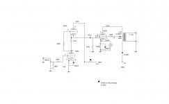
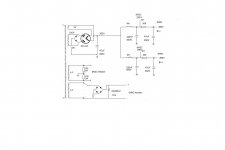
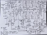
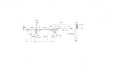
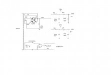
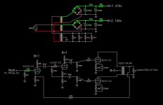
  • Tubes are 6SF5 (half a 12AX7), E1148 (slight variation on 7193/2C22, so half a 6SN7), and 6DY7 (two beam tetrodes in one bottle, shared cathode and screens).
  • This is my first design with a CCS that isn't under an LTP. Not sure I'm injecting GNFB in the right place, but LTspice says it's effective there. The CCS is set for about 1.34mA, which comes in at 1.4V at the 6SG5 cathode at idle.
  • At a minimum, screens and bias will be regulated. I'll probably regulate the whole thing.
  • LTspice says this will generate 22W at 1.2% THD from a 1VRMS input. However, that's probably over-optimistic, because it's got the plates swinging to 30V on the low side and the same distance from 2*B+ on the high side. Oh, and I also don't have series resistance in the OT model.
  • The OT inductance ratios are correct for the modeled 16R speaker load. That's an artifact from when I was exploring different OT options, because this wants an oddball impedance (14k). I'll fix up the numbers for the 8R intended load.
  • LTspice says the tubes are idling at about 19mA. That's very cold - half of the dissipation limit. The datasheet recommends -20V bias for 400V on the plates, but the only commercial amp to ever use this tube (Stromberg-Carlson ASP-422) indeed sits all the way down at -29V. I'm pretty skeptical - will have to work this out on the breadboard.

DjEztTr.png

Kicker IX405d

I have a Kicker Ix405d on the bench with blown power supplies on the class d side and the ab side.

The class D outputs are all blown too.

The z44n's are physically damaged.

I removed all the damaged transistors and the amp powers on.

I noticed there's zero resistance between the z44 source and drain pads on both power supply sections, is this how it should be before I replace with new z44's?

Thank you

DIY newbie in need of info

Hello all. I just joined the site and I'm looking forward to learning how to work on some of my audio equipment on my own.


Currently I have the following components that need repair.


The Fisher 800T
Bel Canto EVO 2i
Arcam A65 Plus
CEC 3300 CD.


I'm trying to get a service manual from Bel Canto but I don't feel comfortable starting there with diy. Probably the same for the Arcam. I'll outsource those repairs or wait until I'm more comfortable.


I would like to track down a service manual for the CEC 3300 if anyone can be of help. I found a manual for The Fisher online.


I believe I have sourced the transport (Sanyo SF-P101N) for the CEC but have not been able to locate the belt at a reasonable price. CEC wants $100. Any help here would be much appreciated.


I'm going to start my DIY attempt with The Fisher and the CEC.


Thanks for any help or suggestions for getting started.

FS: SAC Thailand Glowmaster balanced KT88 push-pull stereo amplifier

sacthailand.com

This is the version with standard transformers and in original condition, not modded.

Condition wise, there are some scratches on front panel and the roof of one tube cage is slightly depressed (see photos). The amplifier is otherwise in excellent condition with original tubes run at 25-30 mA bias (slightly lower than recommended 30-40 mA).

Originally bought from SAC Thailand in 2014. I'm selling because it has way to much gain for me (26 dB).

Local pickup preferred (item is located in Espoo, Finland. I offer listening and coffee!). I have all the original packaging/crates, but shipping would be on the buyers risk.

1800€

Attachments

  • 20210217_135503.jpg
    20210217_135503.jpg
    974.2 KB · Views: 846
  • 20210217_135452.jpg
    20210217_135452.jpg
    1,001.6 KB · Views: 833
  • 20210217_135458.jpg
    20210217_135458.jpg
    689.1 KB · Views: 786

Mark levinson input stage power supply

Hi guys
I need your help in order to understand something
I tried to understand the differences between the no 33 and the 33H
And one of the differences is in the voltage regulation circuit that supply the input stage
At the end of the circuit you can see 2 electrolytic capacitors of 100V 330uf while in the 33H there isn't any...
Why is that ???

Thanks for all the replyers

Attachments

I-TRIGUE 3200 repair help - right channel has a sneaky problem

Hi all,
I got my hands on an old Creative I-TRIGUE 3200 (Model: MS0760A). It came with a problem on the right channel; no audio was coming out.
When putting it apart, I found that in fact there was audio coming out of the right channel. However, when I tilt it in a certain position, then the audio is gone.
Left channel works no matter what.
I'm sure there is a most likely some crack somewhere along the right RC jack connection, but I can't determine where. I've refilled solder in some of those nearby traces, but to no avail.
I, sent a request to creative about this product, but they said they got no support nor documentation for the product as it isn't sold anymore. (I knew it was a long shot)
I was wondering if anyone:

  1. Run into this same problem and solved it?
  2. Propose a way to solve this problem?
  3. Has reverse engineered the schematics for this product's board and doesn't mind sharing it so that I can guide myself on the signal path.
So far, I've realized that, if measure voltage at the two inputs (2 pins enclosed in red @ inkedright_channel_out_LI.jpg) with the respect to V- terminal, I hear hum on the right channel when the speaker is connected. Not sure if it means anything to someone more experienced.
They are also biased at approximately 6.2V, which seems reasonable since the input voltage is ~12V.

Thanks in advance

Thorens Td166 mkii plinth dimensions

Hi,

Wish to build A new wooden plinth (also called "sub chassis"?) for my Thorens Td166 mkii.

But i really know NOTHING in this...only to make it.

Here I need the crowd helping:
Have you have found here or anywhere A sketch of the Td166 mkii plinth and remember where?
If do - a sketch & dimensions would be SUPER helpful!

I know only to work ... i dont know anything in sketching.

Thank you so much!!!

Decoding the ScanSpeak numbering system

Is there a codex or method, or "secret decoding ring" to ScanSpeak drivers?

For instance, comparing an 18WU/8741T00 to an 18W/8434G00... "18W" is 18 cm woofer, got that... the first "8" after the "/" means it is an 8 ohm nominal driver... got that... but how would I decode that one is an Illuminator and the other is a Discovery? what do the other numbers and letters mean?

j.

Attaching a DAC Dongle to a Phone with MicroUSB

I am very confused . . .


I just purchased a Hidizs S9 Pro DAC Dongle, and want to use it with my smartphone to play music. The manual (for the DAC) says "Just plug it in."


Well, the DAC cable is USB-C (at both ends), but my [older] Samsung phone has a microUSB connector. Do I buy a microUSB-to-USB-C cable, or can I use the 3.5mm headphone output on the phone? I'm assuming the headphone output is already analog, and don't know if that can be over-ridden to output a digital signal.


Assuming I go with the microUSB output, do I need just an adapter, or an OTG cable? I don't seem to be able to find an OTG microUSB (male) to USB-C (female) cable. Can I go with an OTG microUSB (male) to USB 2.0 (female) and then use the USB 2.0 adapter that came with the DAC? That kind of leaves me with a very kludgy system . . .

Predator Call Ideas?

I'm not sure where to post this, so I'll start in the Lounge.

I want to build a portable call for hunting coyotes, but I need something with a good remote control I know I can buy a good one for about $400, but being a DIY guy, I'd like to build my own and save a lot of money. I'd like to be able to operate from at least one hundred feet. Any ideas on a portable amp with a good, strong remote control?
Thanks!

DIY Amp/Speaker Switcher

So after reading DIY speaker switcher I decided to build one my self. Its working well and I'm using 12 pins toggle switcher, since almost all the tutorial use that.

But I came across this switcher which only use 6 pins toggle switcher, and it seem that they shorted the negative connection together. Does this design have downside? I want to build one like this but don't want to fry my amp/speaker.

uMzTvwO.jpg


Thanks

  • Locked
DIY Kit AudioResearch ARC Tube Preamplifier Balanced/RCA IN&OUT,12AU7/ECC83+ECC88/6DJ

DIY Kit AudioResearch ARC Tube Preamplifier Balanced/RCA IN&OUT,12AU7/ECC83+ECC88/6DJ

Hi there,

till now I did more reading than writing but today I need some informations about this what is called a ARC-preamp kit.

https://www.aliexpress.com/item/1005002553663346.html?spm=a2g0o.cart.0.0.58ad3c00858gF4&mp=1

Even if I doubt that there is a real complete ARC schematic behind it, there could at least be some approaches. But the more important point is that there is also a suitable housing for the kit which makes it more interesting.

I have already created a few tube projects (HiFi- & guitar-amps) but the housing work with normal tools is not that easy.

Does anybody know what's behind that circuit diagram in terms of audio (the periphery pcb is more of a welcome addition)? Is it worthwhile?

Cheers
Claus

Conversation with Dr. Floyd Toole

Thought you guys might enjoy this chat I had with @Floyd Toole a couple days ago.

Thanks to Dr. Toole for being a sport and entertaining my questions and generally being such a nice fellow. Hopefully we can do this again sometime soon. 🙂

I'll try to add timestamps when I can. But for now, I simply don't have the time.


Chat with Dr. Floyd Toole - YouTube
  • Like
Reactions: Ethloas

Are Satori's worth the extra money?

I am on the verge of building my first set of speakers and had pretty much plumpt for the SB Acoustics, either SB15NRX30 or SB15MFC30. Recently though, I have been looking at the Satori MW13P, which appeals to me being a smaller driver but still having reasonable Fs, and wondered if anyone has compared these drivers and could possibly offer opinions on the quality difference and whether they're worth paying twice the price for?

Thanks!!

proper grounding connection between two pcb

I have two seperated pcb one is power supply pcb and the other one is noise sensitive DAC pcb.

I put vias on both pcb to make a pin to pin power connection please see attached picture.

In power pcb i use noisy isolated dc/dc converter (switch freq. 100khz). To clean up noise, i use LC filter + cap multiplier right after isolation and then a linear regulator.

I must connect power supply ground plane to the DAC pcb ground plane. The question is, which location/locations is good to do that on both pcb?

Attachments

  • simplified.png
    simplified.png
    74.8 KB · Views: 163

ANY SUGGESTIONS FOR A DIY RIVAL TO BOSE SOUNDLINK MINI PART 2

Sorry guys, instead of adding to a 2 year old thread I thought I'd create a ne, especially seeing the intention has changed a bit from when it was first started back in 2019.

Over the last 12-18 months I've made a few different things and went down the rabbit hole of 3d printers and small bt/amp boards.

On the topic of both I've been flirting with the idea of a beer can speaker , which is around 0.015cuft volume, uses a 2 inch peerless driver from a Google home and powered by a QCC3008 BT/Amp chip (which is a 5v board). I've tried many variants to date which can sizes, a few of the csr version amps, drivers, passive membranes, vents etc as well, but think I have my combo ready now,

TLDR I'm using and have a programming device for the QCC3008 amp and wondering if there are any settings in the attached image to mimic the performance of a.soundlink mini, either via EQ settings, bass boost, crossover etc.

I fear with a lack of TS specs available for the peerless driver due to being special order, that the enclosure may be undersized, but want some good sounding low end at all volume levels, which might be starting at 100hz and above considering the size, with a roll off for some od the lower end from there.

I would love to hear any suggestions in tweaks to the amp via the USB SPI programmer I could do to make this battery powered lowfi device next level.....I'll share the STL'S as well If people want to develop their own and share what they've done

Attachments

  • image_91396.png
    image_91396.png
    806.8 KB · Views: 159
  • IMG_20210723_182155.jpg
    IMG_20210723_182155.jpg
    458.9 KB · Views: 156
  • IMG_20210723_181938.jpg
    IMG_20210723_181938.jpg
    614 KB · Views: 150
  • IMG_20210723_182015.jpg
    IMG_20210723_182015.jpg
    519.1 KB · Views: 157
  • IMG_20210725_075609.jpg
    IMG_20210725_075609.jpg
    234.6 KB · Views: 156

6T4 Moebius resurrection

Hi all,

Quite a while back I built a preamplifier that I am pretty sure I learned about on this forum. I think at the time I had built an Aikido linestage and was interested in preamps. Anyway, I built one designed by a member here, Poindexter, that he had christened Moebius and used 6T4 valves. I think a version was available as a commercial preamp and got good reviews at the time. Anyway, the preamp had been in storage for many years now, and in the course of a tidy up, I pulled it out for a look and to check it over today.

Suffice to say, it is clear from revisiting this old build that I have learned a reasonable amount about building in the last decade! After a fair bit of tidying up functional but janky wiring, improving grounding and redesigning the HV supply, its sounding very capable now. I'll give it a soak test for a while to make sure its stable.

Anyway, none of that is why I'm posting here, the real reason is that no matter how I searched here I couldn't turn up a schematic or a build thread. I eventually found the schematic on a Polish forum, and thought I'd post it here - along with the question - have others here built this pre? Anyone still got it in use?

Fran

Attachments

  • Mobius 6T4.gif
    Mobius 6T4.gif
    7.7 KB · Views: 331
  • Moebius 6AQ5.gif
    Moebius 6AQ5.gif
    17.3 KB · Views: 320
  • Moebius 6SN7.gif
    Moebius 6SN7.gif
    7.7 KB · Views: 327

Low voltage on output tubes for OTL headphone amplifier

I am working on an OTL headphone ampifier with 6SN7 for input tubes and 6AS7 in push pull for the DC coupled output stage. Since this also mean I have a risk of having b+ voltage send straight to my headphones I would like to keep the voltage as low as possible.

I have already fitted a diode/TVS clamp on the output for safety but would also like to keep the b+ voltage low, but how low can I go with the 6AS7 tubes?

I have seen designs from TubeCAD with +/-50V but can i go lower? And what would the consequences or effects of low voltage be? And can I trust my tube models at such low voltage?

The input tubes will still be allowed to have high voltage and will be AC coupled to the output stage.

Buffalo DAC with NTD1

Buffalo II DAC with NTD1

For sale my up to now reference DAC. It was build with as good as it gets parts.
Susume RG smd resistors
Caddock MP930 power resistors
Matched output transistors from GB
For PSU regs upgraded to LT1085/LT1033 from Farnell
PSU includes 4 regs for output stage and 1 as raw power supply for Buffalo
You only need to add trafos, I have EI transformers but I reckon they are too heavy

Buffalo DAC was upgraded with LT3042 regs (Dimdim's pcbs)

Measures and plays perfectly

SOLD

Attachments

  • PC161786.JPG
    PC161786.JPG
    290.7 KB · Views: 790
  • PC151742.JPG
    PC151742.JPG
    267.9 KB · Views: 788

TPA3116D2 new amplifier

Many will say: another TPA3116 amp?

Well, I already have one 3116 amp from Breezy Audio, but I need to install one for bedroom TV setup, and it has to be Bluetooth, which the Breezy does not support.

This the one I'm talking about:

https://www.aliexpress.com/item/1005001708649867.html?ug_edm_item_id=1005001708649867&creative_img_ind=3&creative_img_tpl=153709&edm_click_module=alg_product&tracelog=rowan&rowan_id1=spaml_product_2_picture_square_2_1_pt_BR_2021-07-24&rowan_msg_id=carlCOWS_220_$f08acb0364e94e4faa4e602f62e09931&ck=in_edm_other

Has anyone bought one and is already using?

They mention that you have to install the protection and the heatsink, but do not show what that is or seem to sell it or show it. Does anyone know what they are?

The problem is this: I have a Semp Toshiba TV and it has BT. I have two sources that I have to feed in, but I have to find a way to amplify the sound from both for the external speakers. I did that in the past, but it required two additional boxes and additional power supplied, and available is critical.

I don't trust the quality of the TV's headphone which I could link the amp to, so BT might an option. How's the quality of BT audio for that application?

Well, I asked several questions, so let's wait if I start getting answers.

Thanks!

BTSB in a custom RTP (ready to print) 3D case - the TH board

If Wined is ok with using his 3D CAD file (I just asked for his permission)

https://www.diyaudio.com/forums/gro...r-se-bal-se-bal-buffer-gb-22.html#post6711584

- I would get at least three BTSBs. (Maybe four/ five?) …

I haven’t yet got one for either of my two TPA amps; one of which is a 4 channel - so it alone really needs two BTSBs (which xkr generously got working and tested, taking a bit longer than the agreed time cost allowance)

Plus, I’ve got three power amps with gain of just 14-20 dB (and another likely lowish gain amp underway!)

And, a very good Musical Fidelity preamp with an excellent * passive output, but the active line output is noisy. I’ve been wondering what to do about that %#! for a couple of years now!

(And purchasing parts & making things in batches … productivity & the work rhythms are better)

Wined’s custom CAD designed case is the perfect size for the TH board. And while I could probably master SM, that would take longer … but the Etsy store doesn't list them at present. When might there be another run?

FS CSX1 stuff

Hi all. Today is a sad day for me. I need sell my csx1 stuff. I sold complete as is. Not for sale only vfets.
They are matched for csx1...
2sj28 KE '25' VGS 6,84V
2sj28 KE '26' VGS 7,67V
2sk82 KE 'A' VGS -7,8V
2sk82 KE 'B' VGS -6,37V
Almost perfect pairs... Difficult find today these matched pairs
Two 25V-25V 250VA trafos
Two Permaneder csx1 boards with 2sk170BL and 2sj74BL soldered.
Two JT-123-FLPCH Jensen trafos
Four Nippon Nichicon 33000uf/50V
Two IRFP240, two IRFP9240

Price... 400 eur + shipping + paypal fees

Attachments

  • 20210708_204801.jpg
    20210708_204801.jpg
    378.4 KB · Views: 328

Role of paralleled EL34's in AES SixPac monoblocks

I'm really enjoying my Dennis Had designed SixPac monos, but I do want to roll some other power tubes in it without burning my wallet to a crisp - a full set (12) of Psvane EL34PHs would set me back a cool 900GBP.

So, I was looking on the internet for the possibility of running it with only a single pair of EL34s per channel (the amp has 3 pairs by default). I came across a great video on youtube (on the MrCarlsonsLab channel) where the amp was opened up, analysed, reverse engineered... the works. This confirmed my knowledge that the output tubes are paralleled, but I couldn't understand exactly what's the purpose for this arrangement. In theory, I could easily remove one or two pairs from each channel and run it like that (after adjusting the bias of course).

Some time ago I removed a pair from one channel, as an experiment... and I expected a drop in output power, but I couldn't notice one. Not understanding what happened, I just put the pair back in and used the amps as designed.

However, I'd still like to understand this, as running it with less tubes (cooler, cheaper) would make sense to me, if performance isn't affected (except output power, which I have enough of anyway).

I've attached the reverse engineered schematic for reference.

Cheers!

Attachments

  • Screenshot 2018-09-09 at 11.43.08.jpg
    Screenshot 2018-09-09 at 11.43.08.jpg
    235.1 KB · Views: 445

Help needed for 2nd DIY project

Hello,
My first project was the Pensil Alpair10p. I have been listening to these speakers the past year and enjoy them very much. As you know they are great with vocals and single instruments music but don't do well with more complex music such as rock which I listen to mostly. I understand the limitations of fullranger and accept them.
As for my second project, I am looking for higher end driver in the $1000/pr price range to build as 40L-50L standmount monitor to match my 6 watt SEP EL84 tube amp. The 2 that come up regularly during my searches are the Supravox 215 RTF and the Jordan Eikona 2.Both have great reviews but will they match up with my 6 watt amp?I have my doubts.The Jordan's sensitivity is 86db and I read that they need current to sound their best.
The Supravox look like a better option in a bass reflex monitor with a Qts=0.46 and sensitivity of 98db. I read that ideally a driver with a Qts = .27-.35 is best for a ported enclosure.I will let the more knowledgeable DIYer comment on that.
Are there better drivers than the Supravox for my intended project?
I appreciate your comments

Balanced B1 with Korg Triode

This thread is for "How to build a Balanced B1 Korg Triode" preamplifier.
First, the hardware, I purchased two sets of PCB w/FETS and Korg Triode tubes from the diystore. Boards were stuffed the parts from the BOM with Nichicon UES 1000uF filter caps and Panasonic 10uF film caps (these were the extras I mistakenly bought while building a BZLS).
Once both boards were stuffed and the test voltages confirmed for both boards, I marked one board for Left + and Left -. With the other board marked Right + and Right -.
I measured each side of each board using REW software, Akitika 1K generator and a Behringer UM2 sound card, for 1.5% 2H negative, 1% 2H negative, null point of 2H, 1% 2H positive and 1,5% 2H positive. Here are the results:


R+ R- L+ L-

1.5% 8.57 vdc 8.61 vdc 8.84 vdc 9.51 vdc

positive 2H


1% positive 9.53 vdc 9.52 vdc 9.41 vdc 10.53 vdc


Null 2H 11.62 vdc 11.43 vdc 11.41 vdc 11.57 vdc

0.043%


1% 12.44 vdc 12.12 vdc 12.30 vdc 12.30 vdc
negative 2H


1.5% 13.07 vdc 12.50 vdc 12.84 vdc 12.70 vdc
negative 2H


This is the same procedure I used for my B1 Korg Triode preamp, the hard part was adjusting each channel in balanced mode.

Attachments

  • IMG_0789.jpg
    IMG_0789.jpg
    341.8 KB · Views: 1,519
  • IMG_0785.jpg
    IMG_0785.jpg
    344 KB · Views: 1,481

FS: Matched 2SK2013, 2SJ313, IRFP240 and IRFP9240 pairs for the VFET amp build

I was lucky enough to get my hands on two “essentials” kits for the VFET amp build made possible by Mr. Pass and the diyAudio store in this thread. Putting together the components for the build, I realized that I have plenty of matched pairs of Toshiba 2SK2013/2SJ313 and Vishay IRFP240/IRFP9240, to offer these to interested builders at a good price (28 euro for the four pairs + postage).

These FETs are substitutes for those already included in the supplemental kit made available by the diyaudio store (unmatched Fairchild FQP3N30/FQP3P20 and Vishay IRFP240/IRFP9240), so if on a budget please do consider if you really need these.

You will still need the VFETs provided only as part of the essentials kit and you will also still need the 2SK170/2SJ74 Jfets or the LSK170/LSJ74 equivalents provided by the store as part of the optional supplemental kit.

As long as I have devices available, I will keep a link here and in my signature to a sheet with the devices specifications and ordering instructions.

Update November 28th:
I have had contacted by members asking if I can sell the K2013/J313 pairs separately and if I could also possibly also provide authentic 2SK170BL/2SJ74 pairs to complete the kits.
I can sell separately the 2SK2013 and 2SJ313 pairs for 20 euro (for the two pairs).
Also, for members taking these kits I can provide pairs of authentic 2SK170BL and 2SJ74BL (Idss matched) for an additional 36 euro. As long as stock lasts....

Simple EL34 6DJ8 Tube Amplifier

I just built this today and sounds as good as the 6l6 6h9c i built , again if I have done something wrong please comment and tell me if wrong. Bass is very strong mids to high are also very good.

Attachments

  • EL34 6DJ8 Tube Amplifier New.jpg
    EL34 6DJ8 Tube Amplifier New.jpg
    50.5 KB · Views: 609
  • EL34 6DJ8 Tube Amplifier Power Supply.jpg
    EL34 6DJ8 Tube Amplifier Power Supply.jpg
    68.6 KB · Views: 553
  • IMG_20210724_150038.jpg
    IMG_20210724_150038.jpg
    678.7 KB · Views: 447
  • IMG_20210724_150251.jpg
    IMG_20210724_150251.jpg
    974.8 KB · Views: 513

Luxman MQ68C tube substitution - potential for Screen Drive?

Hi,

I need some input....I was gifted a Luxman MQ68C a while ago. Originally, the power tubes are the obsolete 50CA10 in triode mode push pull fixed bias with a plate voltage of 400VDC and a 6K OPT. The tube is capable of 35W in that way, Luxman rates the amp at 30W. The original tubes are long gone, and the Chinese replacements have a dubious reputation and are not inexpensive.

I have been putting this project off because I am not happy with the idea of running EL34 in this amp. I did install a 6A 6.3VAC transformer to power the new power tube heaters, and installed octal sockets. The PT has a 0-360V 280mA HV winding on the PT, the 50V heater will be released from duty, reducing stress on the PT.

The original EL34 would put out 19W according to the datasheet, and new production tubes would obviously be less.
The alternative is 6550 in triode PP, this does around 25W, still not at the 35W mark for the 50CA10.

The KT88 does not fit, the sides of the bottles touch. *yikes*

So then I looked at alternatives and came up with two options that I am considering:

1) KT90 biased at 50-60 mA in triode mode. The skinny bottles fit well in the amp.

2) JJ EL509S in Enhanced Triode mode (screen driven). This way, the bias current will be about 10mA per tube and this will make the PT run much cooler. I may not have enough drive from the inverter to get enough power from this tube. But that can be fixed with a Mosfet.

Has anyone done this before, or anything similar? What are your thoughts on these approaches?

X-over realized by Laptop, Open Source and 7.1 AV Receiver over Display Port / HDMI

Good Day,

enclosed find my first Howto. Its about my setting up a X-over with a Laptop, open Source Software and one 7.1 AV-Receiver over DP / HDMI.

https://1drv.ms/b/s!AnKX4vLSHn4Nh5cTCw2UlL4DP9Ly5w

With this solution you can activate two 2 Way or 3 Way Loudspeakers without need of any additional hardware.

If any comments please feel free to contact me.

Regards
Guenter

FS: Turnkey Raspberry Pi DAC Setup

IMG_0352.jpg

Here's a turnkey Raspberry Pi DAC setup - just plug it in, everything is included.

Raspberry Pi 3B+ (Retail $35)
Micro usb to barrel connector power connector (Retail $5)
MicroSD Card 16 GB with a fresh install of MoOde Audio (Retail $10)
HiFi Berry DAC + Pro - this is one of the few DAC Hats that has on dual board oscillators (Retail $53)
Misc. mounting hardware and 6061 T-6 aluminum top and bottom plates forming an enclosure (Retail $15)
iFi iPower power supply (Retail $49)

The retail value is $167 plus shipping from all the various sources. AND, this is built and ready to go.

Yours for $125 plus shipping.

Popping sound from speaker Pioneer A301 Integrated Amp

i was able to repair my Pioneer A301 integrated amp after years of slumber. The amp is working fine but when i hook up my Pioneer GR333 equalizer after an hour of music popping sound comes out from my left speaker. My equalizer has some tight sliding knobs of some of the bands which i loossen it with a contact cleaner. I checked the components afters hours of troubleshooting and they are seem to be fine. Does the sliding knobs of the bands has something to do with the popping sound? since they are stucked for a long time? Thank you in advance.

Help needed: diaphragm sticking to 1 side of stator

Hi,

I just finished building a new pair of esl's. The first days they played fined. But one channel now has problems: it's diaphragm sticks to one stator. I can lower the bias voltage to solve this problem, but this costs me 15 dB sensitivity...
Sometimes the diaphragm doesn't stick to the stator and then everything seems fine.

I have to admit that I forgot to put small (1x1 cm) spacers between diaphragm and wire stators: in my previous esl's I put these spacers in the horizontal middle, every 30 cm vertically, to reduce the effective with of the diaphragm, similar to the silicone dots used by Audiostatic. After attaching the first diaphragm I became aware that I forgot to attach these "spacer dots", so I just tested the esl and it worked fine, until today, now one channel sticks to the front stator.

I'm wondering what can be the cause and what would be a solution? My own ideas:

* diaphram too wide in relation to diaphragm - stator distance: according to a Duch book about DIY els building, a max. ratio of 1:100 should be used for diaphragm width: my d/s is 1.7 millimeters, so 1.7 * 100 = 17 cm width is max. allowed width to get good static stability. But the book suggests to be on the safe side and use 1:70 which results in 12 cm width. My diaphragm is 23 cm width. Solution: put the small 1x1 cm spacers which I forgot in the middle of the diaphragm.

* diaphrahm tension: raise tension. I think this will be difficult. I didn't put much tension as I used ducktape to tension.

* too much difference between distance of stators and diaphragm. (asymmetry)

Any advice what to do and what would be the cause? I tend to remove the diaphragm and put the extra 1x1cm "dots" vertically very 20 or 30 cm.

Power trace on top or bottom layer?

Im trying to optimize a diamond buffer module for my preamp. In doing so ive come to ponder if its a good idea to keep the power traces on bottom layer and then all signal traces on top layer, which is the opposite of the advice ive read in the past.

My thinking is that if the power traces are on the bottom then shieled by a top layer ground plane then top becomes the layer with the lesser radiated interference and thats where the signal traces should go. Please let me know if thats a sound plan 😀

FS: Behringer A500 Amps

FS: Behringer A500 Amplifier

I have a Behringer A500 stereo power amplifier for sale. It is used and has had the RCA input jacks removed due to a design defect. The TRS and XLR inputs work fine. Other than the removal of the RCA input jacks and jumping the required signal-detect lines, there have been no other modifications. It is fully functional and has no issues.

Full specifications can be found here:
https://mediadl.musictribe.com/media/sys_master/hb9/h18/8850223366174.pdf

Product page:
Behringer | Product | A500

Shipping is only within the lower 48 states of the USA, will be via insured UPS Ground service and tracking will be provided upon purchase. Payment is via PayPal ONLY.

I am asking $125 SHIPPED for the amplifier.


[12-Oct-2020: Disregard the fact that two amplifiers are shown in the attached pictures. I originally had two for sale, one of which has sold]

Attachments

  • Behringer_A500_power_amp.zip
    Behringer_A500_power_amp.zip
    139.9 KB · Views: 80
  • 01.jpg
    01.jpg
    129.9 KB · Views: 341
  • 02.jpg
    02.jpg
    127.4 KB · Views: 345
  • 03.jpg
    03.jpg
    87.6 KB · Views: 343
  • 04.jpg
    04.jpg
    134.3 KB · Views: 344
  • 05.jpg
    05.jpg
    129.9 KB · Views: 341

Designing my matching TABAQ center speaker

Hi all,

I built myself a pair of large TABAQ. I am satisfied with its performance. Compared them to a set of Elac Unifi 2.0 UB52, they are not far behind.

Now I am thinking to build a matching center speaker. I know 99% of center speakers are in the MTM configuration. Mid range - Tweeter - Mid range.

However I am not planning to use a tweeter as I am not verse with building x overs.

So my question is there still a benefit of having two drivers in series (two 4 Ohm full range drivers in series).
Would that be same as using one 8 Ohm full range driver?
I assume the output in terms of SPL is the same?

Is the reason of a MTM configuration is to be symmetrical putting mid range drivers on left and right of the tweeter?

Pilot 505 Amp

Some years ago I tore apart a couple of console units. One was a Pilot 505. I put new capacitors in the amp and was working on the MPX unit when I got distracted and never got back. I've just ordered JJ tubes for the amp and would like to see if it works.

What can I do for a pre-amp? I'd like to build your kit unit but haven't the time right now. Is there a reasonable priced phono unit I could use just to test this?

What kind of power does it have and what to do for speakers? The original speakers were largish but without heavy magnets and no enclosure so I'm guessing I need easy to drive speakers, correct?

(this stuff is probably in your beginner's thread, sorry.)

Anything overly bad here?

I have prototyped this on the bench and am hoping that someone with more experience than I can point out anything that I've gotten out of whack. It works fine and sounds amazing to my ear. I just don't want to build a seriously flawed design. The power supply shown in the schematic is using a toroid that I wound myself, using the original primary. I had to draw it as three transformers, but it's actually just three secondaries on the same transformer. I may or may not incorporate a filament rectifier. I'm very interested in regulated power supplies, but have only found information related to specific supplies and voltages. I don't know how to modify them to output different voltages. I'm open to some good reading material if someone can point me in the right direction.


The phase inverter bias is something that I'm particularly concerned about. I am having some trouble grasping how it works exactly. I really like the sound of the ECC81, despite it not being particularly linear. I also happen to have a few of them on hand. The preamp triodes are biased to 3.5mA and 112v plate voltage (310v B+) using a 56k plate load resistor. The 6CG7s are in push-pull and are biased to 13mA at 140v. They are driving an Edcor 12k:4R PP OPT and I am using 32 ohm Grado RS2e headphones. I am currently in the process of winding another toroid to ~450V so that I can run the ECC81 a little hotter without reducing the plate load resistor very much. I tried it with a 10k with the current power supply and it just didn't sound as good to me. The highs weren't as twinkly if that makes sense. I am considering some other preamp/phase inverter tubes as well, and would like to have the extra B+ to push them a little. Thoughts? I appreciate all the help that I've gotten here.


Edit: After posting, I realized that I had the 6cg7s running too hot. I replaced the 820R resistor in the PSU with a 1k6. That dropped the B+2 down to 120v and the 6cg7 plate current to 10.4 mA. 1.24 watts dissipation per triode now. Under the 5watt total (per tube) maximum.

Attachments

  • Audity III.JPG
    Audity III.JPG
    74.5 KB · Views: 447

Mpl

I am planning to build a loudspeaker that complements my MPP. I have build a preamp and Brianco is doing a poweramp so in the next month a system will be made of Phonoamp, Preamp, Poweramp and Speaker for DIY.
The speaker is based on a wideband unit in a baffle.
Under 80 Hz it will be complimented by a dipol woofer and over 7kHz there will be a horn loaded Ribbon.
The wideband driver got developped over a period of one year.
It has a classical paper cone and Alnico magnet.
I got the finished samples some days ago and did some measurements.
The driver is designed for very low distortion.
It is under 0.5% up to 100dB in 1m second harmonic. Thirs id under 0.1%.
Today i will post some measurements.
The driver is in a 90cm by 125cm baffle placed asymmetric due to golden cut.
I will pulish photos and drawings later.
Impedance is 6 Ohm Re and sensitivity is 96dB for 1W/ 1m.

Attachments

New Member from Horsetown

Hello,

New member from Horsetown USA (Norco CA). I've been reading the threads and now I am one. This should be fun thanks for letting me in. I have a couple of vintage systems I working on with a goal to land on the "One". I have a Hafler DH-100 paired with a Speakercraft BB275 and Wharfdale Diamond 9.1 speakers (with GR Research kit) and I have a Harman Kardon TA 5000x paired with TriTrix MTMs. I also have a couple of CD players and a Phillips 777 TT. like everyone I mix and match. I like to tinker with my stuff so almost everything I have has been restored and upgraded. If you have any questions for me about this gear please feel free to ask as I have worked on all of it.

Cheers,
Bill

Phono Pre-amp Tube setup - 12AX7 plate voltage

Hello,

I'm new but I'm going to jump right in.
I have a H-K TA5000x that I’ve been slowing restoring. The only schematic I have found is in two parts, Part 1 has the right side cut off and Part 2 has the left side cutoff, which results in the phono preamp being shown on Part 1 and the power supply on Part 2. Unfortunately, while very similar, Parts 1 and 2 are not same version of the schematic. The specific problem I have is the phono preamp plate voltage feed from the power supply (Part 2) is listed at 190vdc, which I have measured to be 188vdc. This same supply is listed on at the phono preamp in Part 1 as 270vdc, which is then reduce to 170vdc and 120vdc before going to the plates. I have measured the plate voltages to be about 120vdc and 78vdc; this seems very low as these tubes are rated up to 300vdc plate voltage. It plays okay but I think it could be better. I definitely have much lower volume from phono then the radio or Aux and this receiver seems to have a little bit of low volume in general for the watt rating. I’m currently running reissue russian TungSol 12AX7/ECC803S gold pins and I have some used mismatched vintage tubes that work but strength is unknown; there are differences but in general new and old tubes work the same. Should I adjust the power supply voltage to the plates by changing resistor values and if I do what tube performance parameter should I being trying to achieve?

TA-5000X Radio Harman Kardon; New York, build 1965 ??, 9 pic

Thanks for reading and any input is welcome.
Bill

Free to good home

I have been trying thin my collection of audio gear. I have a pair of mltl speakers I built several years ago using the mark audio ch70 drivers. I built them for a bottleneck meet competition for small drivers. These sound very nice with surprising bass. I need to move them on so they are free to a good home. I live in the dc suburbs and won’t ship them. If you want them let me know and come and pick them up.
Viet came and picked them up this morning. I hope the recipient enjoys them.

NAD 3020 series not not helpful!!

So I'm working on one of these that had blown fuses, this appears to be, not supprisingly that the 4 main output transistors were installed without insulating sleeves on the securing bolts. So all I have to do now is sort out the left chennel centre voltage. Now for the good bit, the PCB has no markings to show what resistors are what, only the caps and diodes are marked on are on the board, great!! 😱 Anyone else ever had this?

RIAA Preamp EF804 tube

Hello guys, recently finished my first Riaa preamp with ef804+El84 tubes. The first impresion when started was wow, really good sound, no hum at all and i am very happy with it. Later i have started playing with anode voltage and cathode resistor for ef804, and everytime the sound changes, sometimes it is worse, sometimes it looks better, so the question would be: does anybody in here have expierence with ef804 biasing? It looks like it low current tube, but there is si many variations to try…. Any tips would be a huge help guys, thanks.
I will also upload full schematic, so any sugestions are welcome.

Attachments

  • 40BA0F2F-B87D-4375-8B99-1DE80C91BED6.jpeg
    40BA0F2F-B87D-4375-8B99-1DE80C91BED6.jpeg
    326.8 KB · Views: 568

Wire Voltage Rating For 6V6 Amplifier

I am rebuilding a mono integrated tube amplifier that has been neglected. I will be replacing all of the capacitors, resistors and wiring. The current wiring is 20 gauge SOLID throughout. I would like to use the same because I find it easier to work with than STRANDED.

The 20 gauge SOLID wire I have is rated at 300 VOLTS, the only 600 VOLT wire I have is STRANDED.

Looking over the schematic, there appears to be only a few wires that carry more than 300 VOLTS, pin 8 of the 5Y3 rectifier to pins 4 of the 6V6's. Also 5Y3 pin 8 to pin 1 of V2 (12AX7).

Is it safe to use 300 VOLT wire for the everything else?

View attachment grommes 55pg schematic.pdf

Attachments

TSE-II 300B OPT mA rating

Beginner here, working on putting together a TSE-II 300B with a target operating point of 385v B+ @ 60mA. Jack of Electraprint is suggesting a 65mA rating for the output transformers after I'd initially mentioned wanting a 100mA, saying "all tubes rise in current when driven, it is only temporary or 70% of the peak" (sic).

Is this correct? My reasons for second-guessing this are that, first, most of the OPTs for 300B applications I see have at least a 100mA rating, and I've seen multiple references to a 100mA rating for Electraprint OPTs in particular; and second, my understanding is that in an SE amp the current through the output tubes is relatively constant, varying little with applied signal. I'm not sure quite what to make of his explanation.

How likely am I to run into saturation with OPTs rated for 65mA? Am I guaranteed to run into saturation if I were to later decide to run the tubes at 80mA?

McIntosh C22 preamp clone on Aliexpress

R5jCBuy.jpg


Seems interesting, if perhaps only an MC22 in spirit. Casework looks good enough to fit in a modern system. The input selector is relay based, and the tone stack looks accessible to change for custom breakpoint frequencies. I like that its got room for modifications, and that it's entirely tube.


The original MC22 used six tubes - five 12AX7As and one 12AT7, but it also had a phono section which would occupy several of them. I do think there is supposed to be an additional tube for the output after the tone stage.

Brand is BRZHiFi. I'm not familiar with them so I'm looking for input. More pics of the inside:
BRZHIFI AUDIO MC22 tube preamplifier high and low tone control|Amplifier| - AliExpress

300B TFA-2004 Parafeed w/IT Drive

I have begun a new amp incorporating parafeed, transformer drive and Ultrapath. I already have all of the necessary iron and would welcome comments.

I'm not sure what size small cap I will need to lift the rectifier output from the choke input filter value of 450v to the 520v I need, and I'm not sure if I want to use 10uF or 20uF caps in the driver supply. The cathode resistors are only best guesses as well. Most of the PS caps will be CDE oil motorstarters, as well as the parafeed cap. I want to be able to switch rectification and possibly 300 cathode resistances in order to vary operating points.

I will breadboard (actually plywoodboard!) and fine tune the complete PS through the loading coils and driver transformers using power resistors to draw the necessary current. When I'm sure I have the proper currents and voltages available for the plates I'll repeat the process with tubes to get the cathode resistor values.

Doc B might get a kick out of the transformer/choke picture and the Valve magazine page with the Electronic Tonalities add for the trannies. I was a member of Valve in the late 90's and bought them from him then. $600 a pair for full nickel at the time - those are not the Pinstripes or the Juniors... The chokes are 50H/100ma units I got from Japan a decade ago. I can't remember who made them.

Attachments

MMTMM

So I've read quite a bit on here about using psuedo coaxial arrays to
help control directivity. Using delay with a DEQX Ive been toying with the

idea of making a mmtmm design. But my one preference is to use a 3/4" or smaller tweeter. WHy? Because I like the way they sound and contrary to
many people who say that they cant hear above 10khz I can tell the difference.


I used a peerless 0.5" one time over a 2 inch mid and I loved the way it sounded.


So here's my idea, Im looking for input if this would work and and tweaking ideas you all might have.


For the tweeter using the Wavecor TW013WA01 13 mm, flanked by two Morel MDM 55 followed by 2 RS125T*8 5" Reference Woofer Truncated woofers. With this configuration I can get a very tight grouping.


My crossovers would be around 1100hz and 3000hz. I can get the center to center spacing around 132mm and 322mm for the woofers!


What I'm looking for is really good imaging, nice resolute mids and highs. I dont need super deep bass or loud spl as I live in a condo. Again this would be a purely active setup ran off of a DEQX so no crossovers needed.


Thoughts???

Attachments

NGSpice compatible audio op amp.

Picked OPAx134 op amps because they have a good rep. Couldn't get them to work with KiCad/NGSpice. That's a morning I won't get back. Apparently you need NGSPcice 35 which is due for release RSN.

While poking around I read the OPAx134 doesn't like being a unity gain buffer. Since that's what I need for much of the circuit, BAD CHOICE.

Looking for recommendations for an Op Amp that, in order of priority:

- Has a great subjective sound
- Has models that work well with NGSpice
- Works well with unity gain
- Is easily available in Europe

That's the big ones. Small ones that would be handy but are not deal breakers:

- Is available in 1, 2, 4 versions
- Has the same pinouts as OPAx134
- Works well objectively, for bragging rights

Suggestions welcome. I hope the requirements are too specific for general Op Amp wars!

Unmarked TTA1943 and TTC5200 transistors?

Anyone purchased any of these unmarked transistors from EBay? and do they perform to specifications?
These transistors appear regularly on EBay by a UK based seller called "nikkoelec" which is in fact EBay trade name for Nikko Electronics Ltd, Omar Dalbani, 358 Kingston Road, Epsom, Surrey, KT19 0DT. This is virtually the same company as SWL Electronics Ltd and Dalbani Ltd.
The transistors they offer are specified as "Unmarked" and "Generic"!
As far as we know TTA and TTC transistors are a registered propriety Toshiba transistors which means that no other manufacturer can legally make any such device number. Also, it is well known that Toshiba does not make "generic" versions of their devices nor unmarked ones and all TTA and TTC devices must be laser branded and traceable.
Therefor we feel that it is imperative to bring a strong warning to all members.

FS.Electra Print Audio Co.VT2KB,300b types Pair Single Ended Output Transformers.$600

Electra-Print Audio Co.

Model VT2KB

One Pair (2 matched pieces) Single Ended Output Transformers
about 14 lbs each ( yes, very heavy duty )

$600 per matched pair

it is primary 2.7k ohm with high wattage ( high 160 MA )
Multi taps secondary from 2 ohms to 32 ohms ( color codes available )

for we300b types vacuum tubes ( yes it works with regular 300b tube with better bass )
such as ...
KR 300b 300BXLS KR 52 842 ... Vaic / emission labs VV30b VV52 520b 320b 842 1605 etc
(not limit to, depends on your application, i have tried with all those tubes about up to 30 watt output )

was removed from working amplifiers
so , they are good in working condition ,

will come with new unpainted matching end bells shielded covers
so you can install easily the way you want

with difference position bracket for your need

declaimer .. please be understood that these are amplifier parts, actual application depends on your setting and design spec, however may be able to assist after sales for best of my knowledge

my price is simply including PayPal fee, actual shipping will apply depends on your location

Local pick up welcome ,

Coupling Cap Output in Phono Preamp

I'm upgrading a nice phono preamp. It has inexpensive output coupling caps (some generic type). I'd like to play around to see if a premium or at least better than mass production inexpensive cap would improve things.

This unit has 2 30uF film caps coupling two 6922 tubes to the output to single ended RCA outs. That seems like such a massive size. Do I have some leeway in going down in capacitance? I don't like messing with a designers voicing but caps of that tolerance start getting huge when you buy better product.

Rockford Fosgate T20001BD Problems

I have a Rockford Fosgate T20001 Power series amplifier, board ID PC-4755-A.

It powers own, without going into protect. As soon as it does, there is a clipped signal coming out of the output at rail voltage. It also drains the rails very quickly as soon as you power off, roughly 30 second. It makes a little screech sound when you power it back on ONLY when it has drained the rail voltage.

I can hear a slight buzzing sound coming from the output area, but I can't pinpoint it.

This is all with no audio input, RCAs are unplugged, and the amp board is still mounted into the chassis.

I did not have any shorted FETs, and the power supply gate drive looks normal (tested without 12v input, just remote and ground). Once 12v and remote are applied, it looks terrible.

Any ideas on what to check?

Attachments

  • PXL_20210722_181730630.jpg
    PXL_20210722_181730630.jpg
    815.2 KB · Views: 125
  • PXL_20210722_180847073.jpg
    PXL_20210722_180847073.jpg
    959.9 KB · Views: 148
  • PXL_20210722_181746490.jpg
    PXL_20210722_181746490.jpg
    1 MB · Views: 204
  • PXL_20210722_181758836.jpg
    PXL_20210722_181758836.jpg
    1 MB · Views: 119
  • PXL_20210722_181803616.jpg
    PXL_20210722_181803616.jpg
    1 MB · Views: 112
  • PXL_20210722_181810811.jpg
    PXL_20210722_181810811.jpg
    1,012.3 KB · Views: 88
  • PXL_20210722_181818880.jpg
    PXL_20210722_181818880.jpg
    993.1 KB · Views: 87
  • PXL_20210722_181823296.jpg
    PXL_20210722_181823296.jpg
    1 MB · Views: 95
  • PXL_20210722_181827868.jpg
    PXL_20210722_181827868.jpg
    1 MB · Views: 88

Leaving amp switch to On all the time

My amp, an Usher R1.5 consumes 55 watts when it is "off" as it retains a current even when the power switch is on the "off" position. This is to keep the amp in warmed up mode 24x7. To avoid using more electricity, what I want to do is to add an external power switch and leave the amp's power switch to ON all the time. Would there be any adverse effect when turning on the power using the external power switch while the amps switch is on the ON position?

RH84 Rev2 - suitable speakers

Hi everyone,

Does anyone have any advice or experience on building suitable speakers to go with a RH84 Rev 2 SE amplifier.
I think it will output between 3-5 watts.
I do have Fostex FE126EN in the Fostex BR design box and can partner a sub woofer with them.

However I’m interested in a 8”, 10” or 12” speaker to avoid the use of a sub woofer.

My listening space since moving is very small 3.5m x 3.5m
With Suspended wooden floors (or floorboards)

Thanks

Lee
Projects by fanatics, for fanatics
Get answers and advice for everyone wanting to learn the art of audio.
Join the Community
507,796
Members
7,888,820
Messages

Filter

Forum Statistics

Threads
406,260
Messages
7,888,820
Members
507,796
Latest member
MAYA MAJIMA