Dual 21" Down-firing-Port Subwoofer Build

This is the new thread for the 2x 21" down-firing-port subwoofer build(2x B&C 21SW152-4), it was previously discussed HERE in regards port design suggestion.

This 21" subs will replace the current single Ultimax UM18-22 in a 5-FT^3 sealed enclosure, wanted some lows, strong midbass and low distortion on my 2CH music setup.

Final project specs:
Material: 6x 5/8" MDF-Light 4'x8' sheets.
Measures: 42" H x 24" W x 27" D, (46" H with feet), nominal.
Walls: ~1.25"(dual 5/8") thick walls, ~1.9"(triple 5/8") baffle with braces.
Finish: Black-mate laminate.
Volume: ~9.5 FT^3 Net. after port/driver/bracing.
Weight: ~222 lbs (~180 lbs without driver)

Initial subwoofer testing/setup:
DSP: DBX DriveRack PA2
High-pass xover: 16Hz BW4
Low-pass xover: 60Hz LR4
PEQ's: Off
Delay: Off
Subharmonic Synth: Off

My "subjective" listening impressions:
After getting them in place and connected, I've played some EDM and Pop music and I was a bit skeptical at first, then I remembered that I had to invert the subs phase, after inverting the phase resulted in an instant jaw-drop followed by an ear-to-ear smile, one box just blown away the sealed UM18-22 and I've disable the PEQ's previously boosting the 20~28Hz range on the sealed sub.

Notes worth mentioning:
The B&C 21SW152-4 drivers were installed without any breaking-time, so the subs will significantly dig lower overtime as expected.

The room measurements are 10'-9"W x 9'-2"D x 8'-4"H, just small.

The enclosures were tuned to ~19Hz regarding WinISD, however since the 8" port clearance from top wall is 7.75", port clearance from floor is 4" plus 2 large pillows, the final tuning dropped to around~17 or 18Hz, while I don't had at hand DATSv3 nor a diy impedance jig, I've tested with an adhesive tape and cranked up the amplifier and used a tone generator, so far when the tone generator was set to 17Hz, the woofer drop excursion dramatically and everything in the room was insanely shaking and I feel the high pressure, I didn't hear any port noise/compression when testing so far.

Complete step by step build log HERE

Some build images:

The triple front baffles.
IMG_0211_Snall.jpg


Deluxe 6 prong T-Nuts epoxied.
IMG_0185_Snall.jpg


The Ankh shaped braces and port support.
IMG_0343_Snall.jpg


Gluing started next to a 16oz glue bottle for size reference, I've used my favorite glue TB3.
IMG_0412_Snall.jpg


The braces in place.
IMG_0420_Snall.jpg


Interior view of the port supporters embedded on the braces.
IMG_0429_Snall.jpg


Spreading a generous amount of glue per brace and top/bottom walls.
IMG_0436_Snall.jpg


Internal preview of one box almost ready, back wall non yet glued.
IMG_0453_Snall.jpg


Port dry-run test before sealing it with RTV and gluing the back wall.
IMG_0439_Snall.jpg


IMG_0508_Snall.jpg


Port top/brace clearance.
IMG_0494_Snall.jpg


Port being sealed with 100% RTV.
IMG_0523_Ed_Snall.jpg


Applying few turns of Scotch blue tape for port tighten.
IMG_0529_Snall.jpg


Port being evenly pushed gently with a small piece of wood scrap and a rubber hammer.
IMG_0532_Snall.jpg


IMG_0540_Snall.jpg


Port back view.
IMG_0558_Snall.jpg

IMG_0581_Ed_Snall.jpg

IMG_0591_Snall.jpg

IMG_0594_Snall.jpg

IMG_0603_Snall.jpg


Complete step by step build log HERE
For reference the mains build log HERE

Regards

Raspberry Pi streamer "Controller"?

Hey i was thinking about a sort of controller (with a arduino) for raspberry pi streamers, which mostly act as keyboard for multimedia controls and maybe (maybe as optional thing) receive data over serial from a little script to display current song/volume etc, just connected over usb so it can be put on desktop with the raspberr pi in its own case
i thought about maybe a 3,5" touchscreen display and do everything over that

beside the usual multimedia controls it would be kinda nice to do more things like, switching inputs, switching radio stations etc, i think the easiest thing would be to still just use the ardiuno as keyboard but bind different key(combinations) to some actions of the streamer via a script, so possibly also easy adjustable to all kind of streamer softwares

unfortunaly browsing the filesystem for example wouldnt be possible but the display connectors needs to be in close proximity to the display and a display on the rpi unit itself would be kinda pointless in my case, i need some seperate station/controller on the desk
is there maybe a way to make a seperate unit with a minimal rpi like the zero 2 and actually couple it with the main rpi over usb?

What you guys think about this idea, would there a more easy way todo things? (maybe a hdmi/touchscreen display? to actually support the streamer interface or should i just settle with a cheap tablet to open the webinterface ? (i think that would be actually the easiest solutions, no software required working out of the box))

For Sale Korg NuTube B1 circuit only (no chassis) *but with a twist*

For "sale" is the bare working circuit for a Korg NuTube B1 I bought and built from the diyaudiostore, with an additional power conditioning board, Mark Johnson's PO89ZB, I added separately. I repurposed the chassis, the switches, the pot, the RCA and power jacks, and the wall wart for one of Papa's B1s so I have only the circuit available. This B1 Korg was working and stable when I pulled it, and very rarely had any microphonics. Please don't complain about the solder joints though, not all of them are pretty!

Now here's the catch. I will "sell" this to anyone in the continental US who can show me a receipt for at least a $50 donation to diyaudio. It's fine if it's a month or so old but I'd rather it be recent, as in since the site upgrade. So if you want this thing & have such a receipt, talk to me. Happy Tuesday!


IMG_6824.jpg

IMG_6822.jpg

Attachments

  • IMG_6822.jpg
    IMG_6822.jpg
    668.4 KB · Views: 103

Subwoofer Overload Protection

Hi everyone.

I have a few questions regarding subwoofers, amplifiers and mainly overload protection.
It is going to be a big post here, so I've marked all my questions in bold.
Since I'm new to PA systems and I'm only doing this as a hobby I still have a lot of questions regarding all the PA stuff.

My setup and how I run it:
Speakers:
  • 2x JBL PRX 412M for the high frequency
    • 1200 W Peak, 600W Program, 300W Continuous
    • 8 ohms
  • 1x JBL SRX 828 for the low frequency
    • 4800W Peak, 2400W Program, 1200W Continuous
    • 4 ohms
Amplifiers:
  • the t.amp E-1500 (for my tops)
    • Running in stereo mode
    • 950 Watts per channel
  • Crown XTi 6002 (for my sub)
    • Running in bridged mono mode
    • 6000 Watts

I usually set up small events (~30-50 people) where heavy bass music is played (Techno, Psytrance, Hardstyle, Frenchcore and Uptempo etc.). That's why I bought the XTi 6002 (Class I amp). I've read in a lot of forums that there is a big increase in the quality of the sound compared to a D-Class (or other classes) amp. My goal is to get a huge "woah" regarding the sound quality from the attendees of my events and I think the decision to get a class I is leading towards that goal.

The problem now is, that the amp is can deliver a lot more power than my subwoofer can handle. So I've activated the limiter on my XTi 6002 at -3dB with almost instant attack (0.1s).
I thought -3dB is half the amount of noise, so it should cut the power in half (3000W). I'm pretty sure it doesn't work that way.
Is there any possible way to calculate at how much watts my amp is limited at what limiter (decibel) configuration?
I found the following calculator from crown (dB Power Ratio):
https://www.crownaudio.com/en-US/tools/calculators

The calculation is dB = 10 * Log (Pout / Pin). I think this is the right calculator to use, is it?
Is there any article that can describe this calculation and how decibels and power output are "connected" with each other?
I really want to know what I'm doing, so I won't break anything.


I recently did my first few events and I had the limiter set at -3dB and put the volume of the amp all the way up (because it will limit anyways, if I hadn't any limiter active I'd never do that). At the events I noticed most DJs tried to get more bass or volume and just turned up the gain, low-end EQ or volume on the DJ controller. At some point my limiter on the bass amp did his thing and stopped increasing the output.
However I didn't have any limiter active on my high frequency amp. So this one just kept going and got louder. This resulted in a lot louder high frequency and the bass felt like it wasn't even there.
I read on some forums that a subwoofer should be able to handle a bit more power than it's peak value (in my case 4800W). Is this the case and how much power over the peak value is too much? Would I even be fine with no limiter at all?
I just don't want to break my subwoofer. And if that means I have to set the limiter a bit more aggressive, I'm fine with that.


I'm also looking forward to getting another subwoofer and change my amp. For this the Crown I-Tech 4x3500HD looks nice (4-channel amp).
It delivers 4000W per channel at 4 ohms and I wouldn't have to upgrade my amp if I want to get even more subwoofers.
However, if I only connect 2 channels onto a 4 channel amp. Will the unconnected channels just do nothing or will the power be "transferred" to the other connected channels (so that I have double the power on the other two channels in this case)?
I'm pretty sure the power won't be transferred but I want to be 100% sure, so I better ask.

Cheers

300W Vs. 500W subwoofer?

Hi all!

I am looking to make a 8" subwoofer and amplifier.

I have a 200W audio amplifier, which I was looking for advice on in this thread 200W amplifier design .

Does anyone have any good speaker companies? So far, I'm leaning towards skaraudio.com daytonaudio.
I'm thinking of getting their 8" 300W subwoofer.

When I have a 100W amp for a subwoofer, is a 300W subwoofer good? Would a 500W subwoofer sound better even though the amplifier is only 100W?

Thanks in advance!

Issue on Yamaha's TC-720 Dual Capstan Cassette Deck - no correct Tension of Tape across the Head

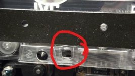
There is to observe an unwanted looping of the tape instead a correct tension across the head.
First idea was to replace the belt by a new one.
After done this the unwanted looping wasn't gone - check out the image.
The left capstan rotates a bit faster than the right one - so as if the capstans had been swapped.

What is therefore the reason ?
Is it a typical effect on this model ?

post #1098 under
https://www.diyaudio.com/community/threads/what-did-you-last-repair.313739/page-55describes in general, what mechanism is it exactly, that maintains the exact proper tape tension across the heads in such cassette drives with dual capstan

This thread don't provide the wanted information:
http://www.hifi-forum.de/viewthread-185-4462.html
Maybe one of the member knows more - thank you very much for an advice.

Attachments

Beautifully crafted transmission cabinets, disappointing sound. Upgrade?

So i bought these beautiful locally crafted 8" transmission line speakers. The company is now extinct sadly. (but i got them for an amazing price because of that.)
The cabinets are stunning and very inert. Made out of Plywood with a native real wood veneer.

nRSHi5I.jpeg

Tweeter is a Dai-ichi DT-81 https://mega.nz/file/kQBQTDoS#qX3DtvMSzE9EnrmaVq-fWHBuMZocYfgWJGqBjSZi4M8
Mid - Response CW2192
Woffer - Response CW2196

Picture of the crossover for the mid and tweeter. Woofer just has a 9mH inductor in series.
https://mega.nz/file/sYQhWQRT#mv9-vGMiIxP4TJ5KTRLhibM3HcwISKbt7qlCMhEtpf8

Link to way-back machine achieve of Pure-sound websight.
https://web.archive.org/web/20160801014151/http://puresound.co.nz/?page_id=204
Unfortunately the High's somehow sound veiled, and also a bit fatiguing as well?

Because i got them for such good price, and the cabinets are so nice, i think upgrading them would be a good option.

Is this just a case of Finding a new tweeter that will physically fit, has a similar sensitivity, and desirable frequency response?

Any thought welcome.
Skyfire

Kicker DX500.1

Same issue as this thread only I dont think this one was ever solved: https://www.diyaudio.com/community/threads/kicker-dx500-1.270379/

Amp takes about ~8 seconds to fully power up.
During that time, theres only 1.2vDC across speaker terminals.
After 8 seconds, 12.8vDC across speaker terminals.
Amp rail voltage is 56vDC. I know this is a
I know there should always be about 27vDC on speaker terminals referencing ground, but one of the terminals is only at 14vDC. That terminal with only 14v on it; fets of this side are getting just every-so slightly warm to the touch.
Amp idles at 0.5A.

I've found R273/R274 underneath looking to have gotten hot but still measuring correctly at 8.8ohms as they're paralleled.

This amp is using two IRS20957S in the output stage. The partial service manuals on file for DX300/DX700 show HIP4080 as they're different amps.


Any help with why I may be seeing DC on speaker terminals.?

Behringer Xenyx 1002FX: can't seem to use it as a preamp without FX. Anyone familiar with this?

I've had a Behringer Xenyx 1002FX for a few years, but never really got into using it. Now I want to use it as a preamp for a condenser mike. However, whatever is selected on the fx knob seems to either have intense effects or has an unusable amount of reverb, and low sound quality (eg. 0 selected with the selector knob). It has always been like this, and I bought it new, but I even wonder whether it is faulty. Anyone know about this, before I chuck it out or take a hammer to it?

CD Transport Emulation

Hi All,

I've had recent problems with the laser for my Pioneer PD-91 CD Player and it got me thinking:

Lasers for old transports like mine are becoming harder and harder to find, with some models almost impossible to source any longer.

It would be a travesty to allow some of these players to die out because for the most part they are built and designed extremely well, (not to mention great sounding in their own way).

I know that for older gaming consoles there have been a number of successful recent implementations of 'Optical Drive Emulators' (Sega Saturn, Playstation etc..) allowing the user to replace the CD transport all together with a PCB board and hard-drive - this got me wondering of how hard it would be to implement something similar for vintage CD players.

The idea would be that this 'Emulation Board' could replace the CD transport with a SD Memory card or hard-drive and simulates the process of playing a CD allowing your player's DAC and output stage to still be put to good use.

Of course, this would be a shame for a lot of really well built transports (like in my Pioneer PD-91), however, in a world without suitable replacement lasers, what other options would you have to keep these players alive?

My hunch is that something like this must be possible, given that it works with gaming consoles (which have the added hurdle of anti-piracy protection)..

Thoughts?

Fish

TC9 line array passive EQ?

In my quest to stay away from DSP and keep it all analog, I was thinking whether it would be possible to do a large array (25 pcs) of TC9FD18-08 and EQ it with a passive network instead of DSP?

I really want to avoid a A-D / D-A conversion in the signal path and keep it all analog (lots of vinyl listening). Active analog filtering is an option as well, but only with a higher end diy EQ, not the cheap noisy graphic EQs you find in the pro audio world. Of course I'd use a pair of dedicated subs to augment the low end.

What kind of EQ curves are you guys with TC9 arrays running?

First PCB design, looking for feedback

Hello all,

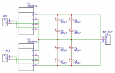
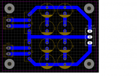
I have decided to try and design my first PCB, so I thought I'd start with something simple; rectification plus caps. This is planned for a phono preamp. Any suggestions for improvements?

Thanks in advance

Attachments

  • PCB_PCB_Rectifier SCH_2_2022-02-07.png
    PCB_PCB_Rectifier SCH_2_2022-02-07.png
    7.1 KB · Views: 172
  • Schematic_Rectifier SCH_4_2022-02-07.png
    Schematic_Rectifier SCH_4_2022-02-07.png
    3.6 KB · Views: 169
  • rectifier_PCB.png
    rectifier_PCB.png
    35.9 KB · Views: 167

Gallo Nucleus Solo driver replacement?

I have a pair of old Gallo Nucleus Solo speakers and one of the original Dynaudio woofers is going out (intermittent open). I just can't throw these speakers out -- must save! I am looking for ideas on a midbass driver that I can use as a replacement in the spherical enclosure (roughly 0.35 ft^3 with a 5" x 1.5" port). I'm thinking I will handle driver blending actively with one of the miniDSP units. Any suggestions appreciated!

the "SPIEKER" my almost 20 year prototype finally done

I'll be surprised if posting images works on my first try, but here we go:

An externally hosted image should be here but it was not working when we last tested it.


I've been working on this forever! and it's finally cosmetically "put together". It is a 2 way with a radian 475 in a 375 hz tractrix (the first few inches are actually a 6 degree conical to match the exit angle of the radian, then tractrix after that). Horn is cast in a mold from plaster, so I can easily cast duplicates. It is thick and heavy. Mated to a 12" dayton hf crossed at 500hz. The enclosure is ported, but i prefer to plug the ports with sewer plugs and run it sealed.

measures well, with woofer, equalized at listening position but measured at 1 meter in room:

An externally hosted image should be here but it was not working when we last tested it.


tweeter/horn only unequalized, horizontal polar response

An externally hosted image should be here but it was not working when we last tested it.


tweeter/horn only csd in room, floor reflection shows up early but it is very clean up to that:

An externally hosted image should be here but it was not working when we last tested it.


The directivity falls quickly at 700hz, could be smoother there, but that also means that the directivity matches the woofer by 500hz. Polar response could be smoother, but a 2 way that plays 20-20k at insane levels with a SET from 500hz up, and huge solid state power below that has been a nice solution.

I've been to several RMAF shows and have heard a lot of gear over the years. I have not heard anything that can better this setup (partnered with a SET) when it comes to voices. They are haunting. Raising the crossover frequency destroys the charm. Resolution and imaging are also top notch.

It does require equalization, I use a minidsp 2x4hd with 48db/octave LR. I am of the opinion that the advantages of using a high resolution dsp far outweigh the disadvantage of the A to D, D to A conversion. Please chime in with any advice. Thanks, Craig Spieker

my last name is german, it's pronounced "speaker"

LT4320 Ideal Bridge Rectifier VFET PwrAmp Application

Hello Folks,

for an active Speaker project I am (re)using VFET Power Amp Modules and Transformer from old Speakers (let's leave the reasoning for that off topic here 😉). The Power Modules need +/-50V for the Driving Stages and +/-42V for the Power Stages.

I want to use LT4320 based active rectification (have the madules already), the toroid transformer's windings are shown in the principle schematic on the left. The My question is: Which of the LT4320 based detail circuits A or B on the right will work (if any)? If both should work, which one is better for a Power Amp?

attachment.php

(Circuits A and B show positive half of supply only, the negative half would be designed like "mirror image")


Thanks a lot for suggestions and explanations!
Winfried

Attachments

Please read carefully: wanted - an HDMI switch that behaves like a relay

Please forget about a full time splitter. I wasted hours to learn it does not work.

My Samsung TV only allows one signal at a time feeding any of its 4 HDMI inputs.

One input. Two outputs. I want it to route the signal to my TV in the “Off” position. In the “on” position, I want it to route the signal to my Surround Sound processor (SSP).

When I turn “on” my SSP, it sends a trigger voltage, either 5V 12V to turn “on” the HDMI switch.

I hope this makes sense. No suggestions of a splitter, please. One possibility that will work is, the trigger “turns off” one of the outputs.

I have a very simple, cheap, ($11), easy to access HDMI switch - one input; 2 outputs. Switching controlled by a simple button. But that too complicated for some of the people in my house.

This “upgrade” must remain inexpensive- as in “well south” of $100. I prefer to avoid adding another remote to the collection.

1000 thanks in advance. Tony

Slot-Loading Optical Drive Mechanism - Repair Service and Maintenance: any Information ?

There are a lot of modern audio components with such kind of cd drive unit (e. g. Tivoli, SONORO, BOSE etc) - mainly are such cd slot loaders in use on lap tops resp. notebooks.
Nevertheless image series and repair resp. replacement advice are very rar on the web, unfortunately.

Here any few URL's I found:
http://muzso.hu/2008/08/17/how-to-c...ading-optical-drive-a-macbook-pros-superdrive Login to view embedded media Login to view embedded media
I want to know mainly descriptions concerning complete dismantling and refurbishing (cleaning/replacing the parts for draw-in and serve out the disc).
Thank you very much for posting some URL's.

Type 45 tube Permalloy Output Transformers

Over the years I have tried many types of output transformers, Double C core EI core , Hashimoto, Amorphous NPA ,Electra Print, Tamura, Audiofeast/ Noguchi Finemet , but had read so much about Permalloy / Nickel being very nice I went in search of some .
I tried the small Sony / Tamradio Nickel 5K transformers , they were very nice but lacked frequency extension at each end.

Tamura 7000 @ 38% Nickel - Permalloy series are no longer made and silly prices on ebay .

Nickel Permalloy has become my new go to for cores .

Raspberry Pi and Volumio

I have partially got an RPi semi running over the last few days. I hit many dead ends and re-formatted the SD card many times. I have got to the point where I have it working and I would like to get it to stream through the Dac Hat.

I have tried flashing Volumio to the SD card having downloaded a Windows version on my laptop. This results in the RPi booting up, opening Volumio and then freezing. It won't then do anything else. After removing Volumio it powers on OK.

Should I be using the RPi and not Windows to install Volumio?

Tube power supply

I have a couple tube projects in mind, including a build of the Valve Wizard's phono stage. I'll be designing toward powering that circuit, first, but would like to have the power supply stand-alone in a separate chassis, so I might recycle at a later date, for another project.

I've repaired several tube amps, radios, an oscilloscope, but never designed anything myself, other than to tinker with coupling capacitor values in my amp (http://seancorron.com/blog/2020/01/30/my-latest-project/).

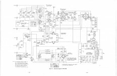
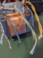
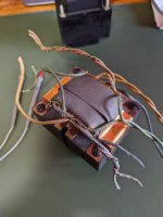
I've got a salvaged tube transformer from an RCA WO-88 oscilloscope (had an "average power consumption of 40 watts"). It seems to have two 6.3v windings (one center tapped, so 12.6v available I think?) various HT taps, and a shield. Schematic and photos of the transformer attached.

Would this transformer be good for this?

Can anyone recommend a power supply circuit? Other than copying the power supply section from the 'scope and modifying for the voltages I desire, what other things might I want to consider?

Is a rectified heater supply always preferred?

Thanks for any tips you might be able to provide!
Sean

Attachments

  • RCA WO-88A Manual 08 (1).jpg
    RCA WO-88A Manual 08 (1).jpg
    317.4 KB · Views: 141
  • PXL_20220205_143045694.jpg
    PXL_20220205_143045694.jpg
    269.7 KB · Views: 134
  • PXL_20220205_143032528.MP.jpg
    PXL_20220205_143032528.MP.jpg
    171.8 KB · Views: 128

Rogers XA75 crossover Q

I am in the process of building yet another LS3/5 'work-a-like' and I found images of the Rogers L35b woofer and XA75 crossover, which in conjunction with an LS3/5 makes the Rogers "reference system" or something.

Anyone have some hint as to the crossover point/slope of the XA75? Of course a schematic would be neat, but I doubt that exists. Searching around only hints at an old for sale add from a fellow in japan?

rogersls35bsubwoofer3.jpg


The Unofficial LS3/5A Support Site was where I initially spotted this image, so if they don't have more (that I can see) I'm thinking this is a long shot...

Replacing Sanyo STK4192 II power amp in a SONY STR AV320

Hi, recently my sony str av320 receivers' speakers were not outputting anything, and protect mode was turned on, so I checked the mainboard and one current detection transistor in the protection section was faulty. Do I replaced it and the protect mode was gone, but still no sound from the speakers. So it looks like the power amplifier chip which it uses ie STK 4192II was no more working.

When I checked locally there are no original ones available now, and all of them in the market were low-quality Chinese clones.

I was looking for a replacement power amp that has a low THD and good performance, can you guys please help me find one?

IMG_1767.jpg

Yamaha RX-V3800 - What am I missing?

Hi,

Been lurking this forum for many years, its a great resource. This is my first post though. I was hoping you could help me figure out what I am missing trying to fix my Yamaha RX-V3800:


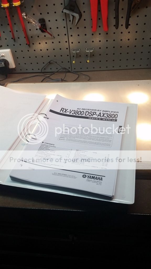
I picked the amp up for a song from a film studio, who were selling off about 10 of them at once (I would have bought more if I had the room to store them). The problem listed was that the amp was not powering on – I was hoping that a power supply capacitor was blown, which is a very common problem for these RX series Yamaha amps. I’ve got another one that had exactly this problem.

Unfortunately, this is not the case, instead the amp powers on, and then shuts off after three seconds. I managed to get my hands on the service manual, which tell me that this is the protection circuitry cutting in, shutting off the amp.


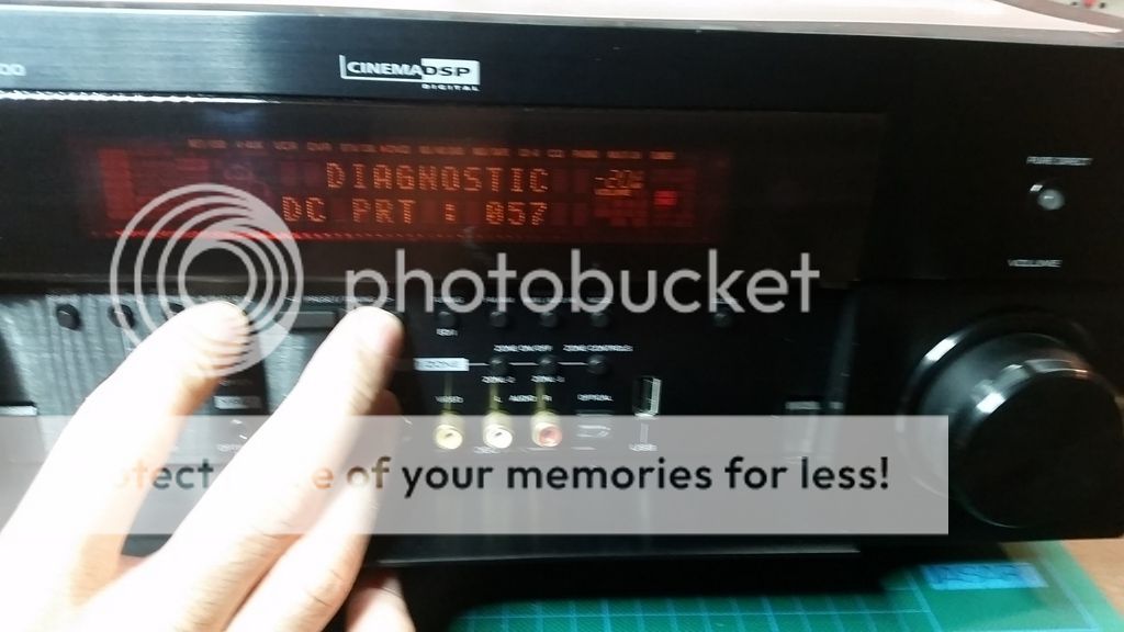
Fortunately you can override the protection circuity by pressing a series of keys on the front panel together:


This brings up a diagnostic test, and also allows you to power on the amp (protection circuitry disabled obviously). The fault displayed is : Diagnostic DC PRT : 057. Consulting the service manual tells me that this indicates a DC voltage across the output.....


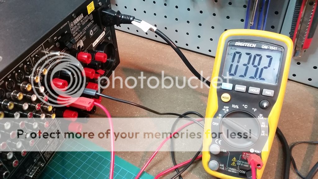
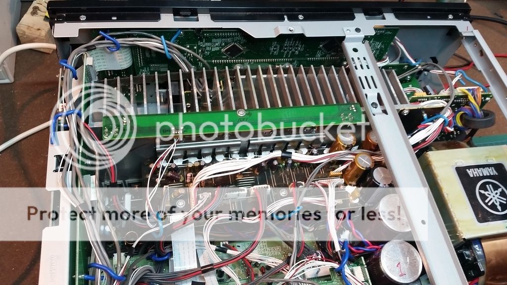
Bingo! 39V across the Right Rear Surround channel. All the other channels seem fine and have around 10mv of DC offset. My first thought was blown output transistors slamming the output into one of the power rails. I spent the next few hours pulling the amp apart to get to the main amp board (of course you have to pull literally every other board out to get to it):


Here my problem; all the output transistors seem fine. No short circuits, and responded appropriately in diode test mode. I even found the schematics for the channels and started checking all the ICs in the circuit:


All the ICs Ive ticked above are good; I was going to start testing all the passives, and even start desoldering and testing out of circuit, but thought I would check here first, in case I am missing something obvious.

The other thing that is causing confusion is that i checked the primary supply rails, and they are 60v +- rails, not 39V. My understanding is that a shorted output transistor would leave a 60v DC offset on the speaker terminals, not 39V.

So my question is, what am I missing? Is there something obvious that would put a 2/3 of the rail voltage on the speaker outputs, without damaging the output transistors (as far as I can tell)?

Thanks for any suggestions!!!

AC MAGNUM AI 170 AMPLIFIER- HELP??

Hi All

I am currently looking at a refurb/ fix of an old (but immaculate conditiomn) magnum ai170 amplifier.

in short it sounds great , but occassionally has a bit of furry distortion on both channels -but one channel more than the other
- not being driven hard-
given its age - I wonder if it may be in need of recapping..

via a process of elimination the preamp appears ok - (tested via feeding tap outputs into another power amp) and bypassing the output stage (feeding outpuit transistors-(TIP 35C's) on the amp via their own power supply does not remove the "distortion""-- so i wonder if the issue is in the main power amp stage prior to output transistors..

Most listening has been via some old B&W DM4's or Stax electrostat headphones.
interstingly the power supply toroid after rectification and filtering putting out about 49.5 v on pos and neg rails
but
Main filter caps are rated at 50v... (!!)
at the very least i will be uprating the main supply caps to something above 60v or so......

i am seeking some schematics etc - despite trawling the net - i have been unable to find anything much on the amp.

far far too nice sounding to ignore.....any ideas out there...?

btw - internal construction is very nice 🙂


many thanks in advance

Cheers

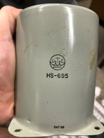
UTC HS-695

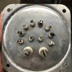
I was given an old piece of "medical equipment" that was tube driven. Aside from some 6SN7's and power tubes, it also had this beast in it. I can not find any information on this type of UTC transformer. From a continuity standpoint:

Center 1A/2A are a coil.
4/3 another
2/1 another
10/8 are?

Any help is most appreciated.

Attachments

  • UTC HS-695 Body.jpg
    UTC HS-695 Body.jpg
    295.2 KB · Views: 126
  • UTC HS-695 Taps.jpg
    UTC HS-695 Taps.jpg
    663.9 KB · Views: 123

Nakamichi T-100 Stereo Audio Analyser

Clearance season!
For sale a Nakamichi T-100 Stereo Audio Analyser

The Nakamichi T-100 Audio Analyzer is a powerful diagnostic instrument which enables you to get the optimum performance from your audio system.

Originally conceived as a tool for the serious recordist, the Analyzer also provides valuable information about preamplifiers, amplifiers, turntables, phonograph cartridges, loudspeakers, and microphones.

The T-100 incorporates the functions of an oscillator, a vacuum tube volt meter, a distortion meter, and a wow & flutter meter in a compact, portable form.
By connecting the Analyzer in parallel with your speakers, you can avoid amplifier/speaker overload when you play back.

Still in good shape as can be seen. Although it hasn't been serviced, it is in good working condition.

There are just a few of them on sale and it's very difficult to set a price for this.
Please, send your offer and I will consider it.

An externally hosted image should be here but it was not working when we last tested it.

An externally hosted image should be here but it was not working when we last tested it.

An externally hosted image should be here but it was not working when we last tested it.

An externally hosted image should be here but it was not working when we last tested it.

An externally hosted image should be here but it was not working when we last tested it.

An externally hosted image should be here but it was not working when we last tested it.

Jeff Rowland Capri S phono stage (looking for a circuit board)

Greetings, dear friends!
I became the owner of a Jeff Rowland Capri S preamplifier. As I know, this preamplifier had an option - a built-in phono stage, which was placed on two boards and inserted into the preamplifier. And somewhere I saw information that these phono amplifier boards can be made by yourself, and there was even a circuit board on the site.
I did not find such a scheme on the site. I wrote to the contacts listed on the site, and did not receive an answer either.
I decided to write to you, you always help me out, for which I am immensely grateful to you.
Maybe this time I will be lucky and someone will have this scheme, or a finished product? 🙂
I look forward to hearing from you.

Ports mouth proximity to driver

Searching on this forum and others , the vast majority of recommendations for placement of the port with respect to the driver say that within a quarter wave of the tuning frequency anywhere is pretty much the same.

However , in this thread it was noted by several members that where there were multiple identical drivers with one placed closer to the port than the other , the closer driver showed visibly greater excursion. However, the thread didn't appear to come up with an explanation for it , though one poster suggested that the closer driver starts to behave as if it were on an open baffle.

So the question is, is there such a thing as too close? and if so , where would the threshold be? Just asking if there is a known minimum safe distance from the driver for planning an upcoming build.

Thanks very much ! ! !

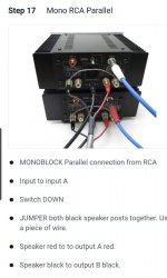
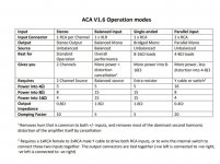
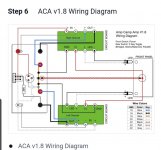
mono parallel aca v1.8

I connected my 2 monoblocks v1.8 aca to monoblock parallel as per build instruction. I checked the ACA V1.6 operation modes table, Is my connection correct to follow the parallel input operation mode? i like to evaluate the highest damping factor 20 in my normal bedroom listening level at 8w (8 ohms) as compared to single ended bridge mono. Pls let me know. thank you.

Attachments

  • mono parallel.jpg
    mono parallel.jpg
    47.1 KB · Views: 210
  • operation.jpg
    operation.jpg
    82 KB · Views: 193
  • wiring.jpg
    wiring.jpg
    79.1 KB · Views: 195

Mic Pre Power Supply +/-15V 1.2A +48V 200mA

Hello,

I hope I am in the right place.

I have some mic preamps with no power supply. The stock PSU is a linear supply +/-15V @ 1.2A and +48V @ 200mA (phantom power).

I would like to build a linear supply that can meet these specs. Off the shelf options like this guy seem too expensive. And I don't like the idea of shoving something on it's own chassis into my chassis.

Is there a generic power supply available that would supply the necessary quiet power? Possibly just as a PCB?

I have an electronics shop, mostly do repair. Should be easy to put something together but hoping for a somewhat off the shelf solution, not looking to design my own board. Hoping a generic PCB supply exists and I can just grab a chassis and toroidal PT and put it all together.

I did see the DIY Audio Universal Power Supply but the board is out of stock and not sure if it's the best option.

I figure I will probably have to use a separate board for phantom power.

Thanks in advance for any input.

Korg 6P1 Preamp Module for Yarra/M2X - Pete Millet Design

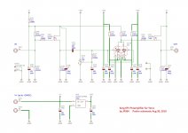
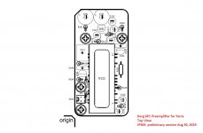
I just got a new batch of Pete Millet's Korg 6P1 NuTube preamp module PCBs in. These fit the Yarra preamp motherboard or the M2X amplifier bolt pattern. This is a valve SE triode design using a compact NuTube vacuum tube design by Korg. The Pete Millet design is used with permission - thank you, Pete! And thank you, JPS64 for a super layout!

More info in the Yarra thread, here.

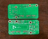
Here is the new green PCB:
attachment.php


Schematic:
attachment.php


Stuffing Guide:
attachment.php


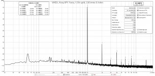
FFT with VHEX+ amp 2.83vrms and 1.55v grid voltage:
attachment.php


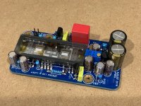
Assembled preamp unit:
attachment.php


Mounted on Yarra motherboard:
attachment.php


The PCBs can be found in my shop here:
Korg 6P1 Preamp for Yarra | Etsy

The BOM in Excel xlsx format is below as .asc file. Rename as .xlsx to open as spreadsheet.

Attachments

  • 6P1-Korg-PCB-green.jpg
    6P1-Korg-PCB-green.jpg
    480.7 KB · Views: 1,338
  • Korg-6p1-Yarra-Schematic-v0.jpg
    Korg-6p1-Yarra-Schematic-v0.jpg
    201.3 KB · Views: 2,042
  • Korg-6p1-Yarra-Top-Stuffing-Guide-v0.jpg
    Korg-6p1-Yarra-Top-Stuffing-Guide-v0.jpg
    137.6 KB · Views: 1,327
  • Korg-6P1-Yarra-test-VHEX-FFT-1.55v-Grid.jpg
    Korg-6P1-Yarra-test-VHEX-FFT-1.55v-Grid.jpg
    226.7 KB · Views: 1,275
  • Korg-6P1-Yarra-test-build-01.jpg
    Korg-6P1-Yarra-test-build-01.jpg
    435.4 KB · Views: 1,384
  • Korg-6P1-Yarra-test-build-02.jpg
    Korg-6P1-Yarra-test-build-02.jpg
    461.2 KB · Views: 1,352
  • Korg-6p1-Yarra-BOM-v0-xlsx.asc
    Korg-6p1-Yarra-BOM-v0-xlsx.asc
    18.3 KB · Views: 183

Ah! Njoe Tjoebe Channel Imbalance

First, I struggled with choosing the correct section for this. I chose the tube section because I believe the cd, dac, and op-amp section of the cd player is ok. Anyway, happy to move it, have it moved for me, or re-post if I chose the wrong section...

Now, to my issue. The left channel rca (and headphone) output is about half to 1/3rd volume of the right channel. I've checked the signal on an oscilliscope and I see a balanced signal on the output of the op-amps as it enters the tube stage. Post tube and output stage the left channel is lower than the right channel. Digital outputs sound fine through an external dac.

I've swapped tube positions, checked every resistor I can find (a lot of surface mount here), pulled the big wima cap and a couple others, checked some other caps in-line, everything seems good.

I'm new to debugging tube amps, but I checked dc voltage of each pin of each tube and I don't know if they're correct but they at least match on the two sides. The filament voltage is 6.3V as labeled on the pcb. The +33V and -33V as printed on the board is correct as well.

In desperation I used the solder pads to set the right channel to 1.25V output voltage while leaving the left channel at 2.5V. This actually did balance the output (as far as I can hear) but is obviously a hack.

Any ideas about what else could be going wrong? As far as I know a schematic was never released publically. Is it possible that even though both tubes are good, the circuit, power supply, etc are unable to drive both and the left somehow suffers?

I know it's a long shot, there is basically zero info on these on the web (surprising). Also, I do realize there may be better cd players out there or that I should just use a transport and a tube buffer/preamp. It's a challenge now though, I just want to fix the thing.

Edit : I've long suspected the relays could be the problem as on my solid-state amps they are almost always culprits with channel imbalance. However, the board has two relays. I believe one is for the headphone and one for rca output and both have the same problem. I can't believe the relays both failed in exactly the same way. However, it could be that one relay is partially pulling down the left signal and it cascades around through the rest of the amp.

Attachments

  • 20220126_231609.jpg
    20220126_231609.jpg
    406.5 KB · Views: 117

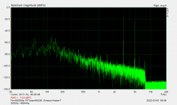
ARTA frequency response

i recently downloaded ARTA to use in conjunction with REW to measure tweak my system, but i've noticed a strong rolloff on the HF spectrum, see attached image of an IMD test i was trying out. we see at ~8khz there is significant rolloff, and after testing frequencies above 10khz, ARTA appears to be gathering no data above that point. evidently i have a noisy room/measuring system, as evidenced by the lower frequency range, but i was expecting more bandwidth than that.

ARTA was set to 48khz sample rate, so we shouldn't have any issues on that front. apart from that, i do get full bandwidth response on REW, which measures as expected out to 20khz. i'm on windows, using standard motherboard audio on my desktop. the mic is a USB minidsp umik-1.

Attachments

  • hf2.png
    hf2.png
    22.4 KB · Views: 129

HIGH Power Class A

I'm looking for input and possible schematics, boards etc. to build a higher power class A amp. In particular though, I want to use the output transistors that I have an abundant supply of MJ15024/25. These are NOS and from the same lot code. I have about 150 of each. I currently have a Pass labs designed A-40 and F5. I would like to have something in the 100W/CH range and have the heatsinks from industrial drives that can support that. I can go with mono's or possible stereo chassis w/fan cooling. I love the sound of the A-40 and it would be great if that front end could be expanded to drive a different output stage to handle higher power. I realize that it is a darlington config but I did read somewhere where Pass was saying it would be simple to convert to a convential BJT with driver. I know that just about all the Pass stuff now is driven with MOSFETs and not the BJTs that I'm wanting to use. Any way interested in what people have to say on this.

Why would anyone disable an amp's balance control?

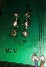
I bought a Yamaha CA-2010 integrated amplifier from 1977 with a balance control which doesn't work. Opening the device, the problem is immediately apparent: a technician has disabled balance control. See picture.

Why would such a thing be necessary? I am asking here before I restore it to stock condition.

Attachments

  • IMG_20210527_023541.jpg
    IMG_20210527_023541.jpg
    506.2 KB · Views: 432

Refurbishment of my Yamaha NS-1000Ms

I have started to work on an extensive refurbishment of my Yamaha NS-1000M speakers and a friend suggested that forum members may be interested. The work is in progress and I am taking lots of pictures of each stage. I've already done a lot of planing but the actual physical work has only just begun.

The pictures and all details can be found here:

http://www.audioflat.co.uk/phpBB3/viewtopic.php?f=7&t=159

I've already made some speaker stands for the Yamaha's and anti-diffraction rings for the mid and tweeter.

I intend to make the crossovers external and upgrade them, laminate the cabinets in gloss black, replace the L-pads with fixed resistors and fill the cabinet holes, re-make the back connection panels, re-wire them and address a few other minor issues (make new badges, gaskets etc.).

200W amplifier design

Hi all!

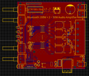
I have designed a 200W HiFi audio amplifier based on the TPA3116. I am trying to make it sound amazing ( 😄 doesn't everyone), so I want to know if anyone has any feed back on design, or things I should add / change.

Schematic, PCB top and bottom, and 3D photos attached.

Thanks in advance for any feedback!

Attachments

  • Screen Shot 2022-01-27 at 10.31.43 AM.png
    Screen Shot 2022-01-27 at 10.31.43 AM.png
    54.6 KB · Views: 231
  • Screen Shot 2022-01-27 at 10.31.54 AM.png
    Screen Shot 2022-01-27 at 10.31.54 AM.png
    46.1 KB · Views: 177
  • Screen Shot 2022-01-27 at 10.32.08 AM.png
    Screen Shot 2022-01-27 at 10.32.08 AM.png
    116.6 KB · Views: 229
  • Schematic_100W Bluetooth Speaker_2022-01-27.png
    Schematic_100W Bluetooth Speaker_2022-01-27.png
    98.9 KB · Views: 240

Luxman r-113

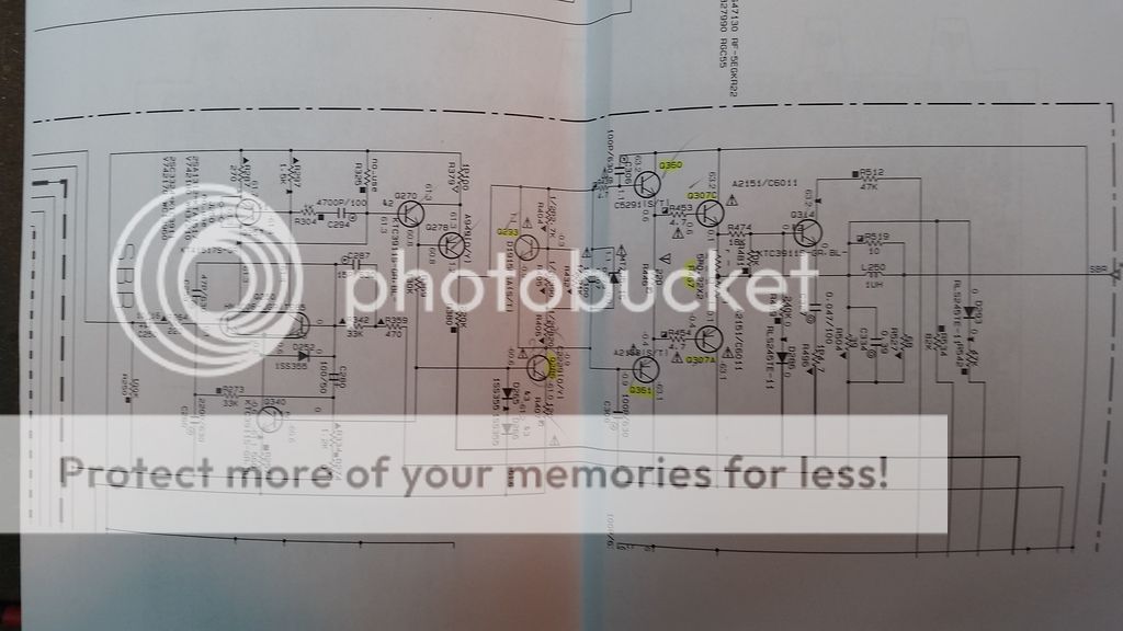
I don't get audio playback from any component jacks except the CD and that only when the straight is engaged. I have the schematic and have some knowledge as to reading it, but there is this broken line that goes to multiple locations on the board. I don't know what this line is supposed to represent. Its in the subsonic filter/cd straight part of the schematic which I have attached. Any advice on this issue and opinion on the problem component would be appreciated. Not sure if I only attached the page or the complete manual, if so reference is page 11. Thanks

Attachments

15" coax drivers for stage wedges

I'm looking to make a batch of stage wedges primary concerns:
1) Output
2) Fidelity
3) Driver cost (disqualifies things like the BMS triax)
4) Driver durability (3" coil or more ideal)

So far the B&C 15fhx76 seems to be a good comprimise: 15FHX76 Coaxials - B&C Speakers

I am quite attacted to the drivers that use a seperate horn to the cone for more narrow coverage and to avoid the cone modulating the HF. I could be wrong about a 60x40 coverage been desirable for a wedge though? Non of the 15" coax drivers I have seen are especialy Hi-Fi with frequency response annomlies around the crossover frequency right in the midband of human hearing. The wedges will be activly processed.

Hawk A19 - Higher power version

As some of you know I have experimented with teh Hawk A19 amplifier to power my Orions. The sound is absolutely stunning but with higher volumes I can hear that the amplifiers for the bass are clipping.
So back to the drawingboard.
The bottleneck is the stabilizer for the DC regulation being a uA7x12. I have now designed a stabilizer that can handle ~60V so I can move from 25V to ~50V rails giving me the power required.
There are a number of members that have bought my PCB's and as soon as I have tested all aspects of the new configuration I'm offering a new PCB at reduced price.
I will publish more details as they become available.

Question about the separate power supply of the AD1865

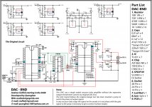
Hi, I'm building a dac with AD1865 (a clone of the note audio), with the cs8414 receiver, both chips have both analog and digital power, and I was wondering: how useful would it be to separate the power supplies of the two chips? Making an analog and digital power supply for the dac, and one also for the receiver, so as to have a total of 4 power supplies, 2 each chip. All power supplies are further filtered with the tl431. Like this scheme.

Tiziano

Attachments

  • DAC-END-cricuit.jpg
    DAC-END-cricuit.jpg
    338.1 KB · Views: 588

Parasound HCA-2200II Upgrade

Our audio shop has closed due to retirement and I would like to share our mod for the HCA-2200II. The only person we have ever shared this with was John Curl many years ago. I hope that this will help some of you who would like a little better sound quality but the mod will improve clarity first and foremost.

Attachments

2Sk100 , 2SK170-V, Yamaha C4

Hello,
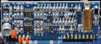
I need to replace a 2SK100. A pair reside in a Yamaha C4 preamp and one appears to be playing up.
It’s a ‘dual jfet’ and one suggestion has been to thermally couple a well-matched pair of 2SK170-V.
Any advice gratefully accepted with regards to the suitability of this solution, better alternatives or, indeed, where best to try and procure genuine stock of 2SK170-V.
Many thanks.

Crossfire C5-1700D

Working on this Type 3 board.

-Has +-16vDC regulated, and +-105vDC rail.
-No DC on speaker terminals.
-Relays release during power up.
-Idles at 1.9A, but at HIGH input signal pulls about 5A.
-I can observe the square wave oscillation at speaker terminals
-No DC on audio pins of any main opamp
-No protection led
-No failed PS nor output FET.
-Output driver board is like the one attached.
-There is barely any audio at speaker terminals. To me what little audio there is, seems like the amplifier is still muted.

Why would this amp not be passing audio to speaker terminals?

Attachments

  • DSCN0036b.jpg
    DSCN0036b.jpg
    115.3 KB · Views: 105

USB to I2S for the 3e audio DSP board?

Hi there,

I recently found the 3e audio DSP board and its very suitable for my needs, but I wanna go a step further to use the I2S input rather than the RCA in. I am a bit new to these things so I spoke to 3e audio, they said their DSP board only takes slave input. I am confused, I searched for USB to I2S board products (like on Aliexpress), there are tons but I dont really see them mentioning Master/Slave mode about their board. I dont know what product I could use, could anybody give me some help and point me to a USB to I2S product that could work with the 3e audio DSP board? Thanks a lot!

For Sale One (1) ScanSpeak 18W/8545-00 MidWoofer (used) for sale

FS: One ScanSpeak 18W/8545-00 Midwoofer paper cone (used) for sale. Hi, this woofer was removed from a working Verity Audio speaker. I replaced the pair of woofers because one was defective, and the other was not. This is your chance to get a great woofer, just need to buy an other one and you are set to build a great speaker. Cost for a new one is 255$CAN + tx (or 200U$). Selling for 100U$ + shipping

Driver is in perfect condition. I can send also the defective one if you want to try to repair it. Shipping box will be heavier, and shipping cost a little higher in consequence.

Btw the only difference according to Solen between the 18W/8545-00 and the new 18W/8545-01 is the basket material, stiffer with the newer -01, both drivers are veritually inditical.

I can use the original ScanSpeak box for safe shipping. The box shown is for the two woofers that I bought, hence the difference in part number.

Thanks for looking

Attachments

  • IMG_20220107_104215.jpg
    IMG_20220107_104215.jpg
    331.5 KB · Views: 207
  • IMG_20220107_104330.jpg
    IMG_20220107_104330.jpg
    155.2 KB · Views: 210
  • IMG_20220107_104349.jpg
    IMG_20220107_104349.jpg
    114.8 KB · Views: 225

For Sale Headphone Amplifier Housings on tubes

Sale of cases of amplifiers for headphones on two tubes.
The case is made of steel, painted with powder paint. The housing includes:
  • chassis
  • bottom cover
  • two caps for output transformers
  • one cap for a power transformer

SW51_DIY_1.jpg


Appearance on the chassis in front. The purpose of the hole from left to right:
  • Two holes for 1.4 jack
  • Hole for ALPS RK27
  • Hole for CARLING toggle switch
  • Hole for LED

SW51_DIY_F.jpg


Rear view of the chassis. The purpose of the holes:
  • Two holes for RCA
  • Hole for AC connector in fuse
  • Hole for power switch

SW51_DIY_B.jpg


Dimensional drawing of the chassis:

1644259696830.png


The case can be used to build a transformer amplifier for headphones on two tubes. For example, like these amplifiers

1644259750054.png


Case cost $50 + shipping
Shipping from Moscow, Russia
There are 16 cases

Measuring TSE-II Filament currents?

Hi All,

I am trying to determine if a new transformer I purchased from Edcor is faulty, as it's buzzing a lot. I am trying to measure the current draw on all the taps while the amp is in operation. At someone's suggestion here I was able to measure the HV Tap my measuring the voltage drop across the choke.

Is there anything similar I can do for two filament currents? Based on the schematic I am not quite sure where I could measure a voltage drop (or DC voltage through the meter).

Thanks!

For Sale Genalex Gold Lion 300B, 12AU7, 12AX7

SOLD

This is a set of tubes that I bought for an Elekit TU-8600 amplifier. They have been used for probably less than 50hrs. These are great tubes, I just got the bug to upgrade so no longer have a use for them. They are the current production models and cost about $450 new. The set includes:

2 - Gold Lion Genalex ECC82 / 12AU7

1 - Gold Lion Genalex ECC83 / 12AX7

2 - Gold Lion Genalex 300B

Please let me know if you have any questions. Shipping within CONUS only. Buyer to cover shipping and PayPal fees.
3.jpg
2.jpg
1.jpg

speaker with two full range drivers

This may be a dumb idea, but being a newbie I will ask. Is there any merit to making a speaker with two identical full range drivers? I know the arrays are always matched to keep the same impedance and two drivers will cut the impedance by half. Will it help sound stage, separation, etc..... I am trying to build something here with some $$$ constraints and this is an off the cuff idea. Thanks for your replies in advance.
Salsero

crowhurst twin coupled amp with dissimilar output transformers

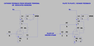
I've been wondering for a long time, if one had two sets of transformers that were not quite the same, say one set 4K to 8Ω, and one 2K to 8Ω, would the twin coupled output stage function with using the 4K in the plate side, and the 2K in the cathode side of the circuit, or vice versa? or do the transformers need to be identical type in order for the circuit to function properly?

I'm not sure why one might want to do this, other than not having a set of 4 output transformers, but perhaps there's benefit to it in some situations?

Resolved - Implemented Seeing Stars

As @tombo56 mentioned, making more donations of different types gives one ahem stars. I was happy to make donations in return for shipping on a couple of items recently, but I certainly don't rank as a 3-star anything (well, perhaps a burro). I'm happy with the good vibes that generally pervade diyAudio, and any potential karma that may ensue.

Could some/all of those be removed without jeopardizing my ad-free nirvana?

Kind regards,
Drew

Open baffle for half critical listening half home theater setup?

Right now in my TV room I have a pair of Snell E/IIIs and a cheap Pioneer receiver. I don't really like the sound but we mainly watch TV on it so it doesn't bother me. I would like to start listening to more music in this room though. It's probably about 18x12' with what I'm guessing are 11-12' ceilings... floor to ceiling windows and hardwood floors (big L couch and rug though). TV/speakers are on a narrow wall.

I have DML panels in my kitchen which is my "main" listening room for now, and I also have some narrow field monitors. Between the two I prefer and have become accustomed to the open soundstage of the DMLs. I don't think I want to do another set of DMLs for the TV room, but I'm not completely opposed.

I guess my main questions are what considerations should I make in choosing drivers for this use. I would say my goals for it are:
  • Wider soundstage
  • Similar low end extension (~40Hz)
  • High efficiency (I would like to use my ZOUDIO as the amp)
I am thinking about some GRS Planars to run down to maybe 800-1000Hz and one of the many OB friendly 12s. I feel like with the narrow room, all the reflections and good XO setup (I will run active) beaming from the woofer shouldn't be an issue. I am also redoing the setup in the kitchen so I could repurpose a pair of the DMLs coupled with a bass driver. I don't want to run a center or rear channels and this is a low dB setup- we mainly watch TV when kids are sleeping and I don't like to listen to music super loud these days. Just looking for insight/advice on such a setup; I feel like it's very common.

Projects by fanatics, for fanatics
Get answers and advice for everyone wanting to learn the art of audio.
Join the Community
507,812
Members
7,889,490
Messages

Filter

Forum Statistics

Threads
406,301
Messages
7,889,490
Members
507,812
Latest member
MwanyamakiJr