• Locked
Investments/Stocks/Funds

Hoping for some tips on general investment etc.

I'll get to the point shortly, but first:
I just recently got enrolled in a education program run by the government that seeks to further educate people with a mainly practical background.
Decided to go for a engineering degree in Electronics as that's basicly the only thing I'm able to apply for, and it's also one of the few things I have interest it.
After I got my acceptance letter not long ago they told me I was eligible for a loan, parts of this loan may turn into a sort of scholarship allowance of sorts upon passing the studies.
This loan has a very low interest rate of currently 1.67%, and is a reliable low interest solution that the government uses to make sure people get a proper education.

I am seriously considering taking that loan, and putting all of it in various stocks and funds. The market is at a low now, but even if it starts going back up a bit before I get the first sum in mid-august I should still be able to "hitch a ride" a bit further up. The plan: If I am able to plan my way in the market "just so" it is possible I could repay a reasonable bit of my mortgage and still have a bit left after fulfilling my education in 3-4 years time.
Even though I am not guaranteed that the loan will turn into "school funds" I am still guaranteed a very low interest rate, so my thinking is that a well-planned portfolio should be well worth it.

Is this a bad idea?

I am concidering spreading it over a few specific tech companies, some stable dividend stocks and something in agriculture.

Thoughts and opinions are welcome.

Marantz SR5300 Amplifier, unusual digital volume display readings?

Hi All.

I'm cleaning up a Marantz SR5300 AV Receiver I acquired and discovered that it displays unusual digital volume readings.

I find AV Receivers can make good value Stereo Amplifiers.
The SR5300 pumps out a claimed 80 rms per channel in Stereo mode.

The problem with this one is that at zero volume it displays -75db.
Pumping up the volume I can get to around -12db at which point it's quite loud.

Is this normal?
Is there a way of displaying a more conventional format.
thanks C

Monsoon speaker parts

A while back I picked up some unused Monsoon Mh-500 2 way satilite speakers and
2 pairs of the Panels from the MH-700 . I was thinking about using those larger panels
from the MH-700 in a MTM with the smaler panel from the MH-500 as the tweeter
but neverf did so if anyone here needs these for parts just let me know and no I don't
have the autio contgrole box that went with these oh the panels from the MH-700 don't
have the plastic feet. If by chance tou can pick them up in zip code 30290 you can have
them free. Or other wize the cost of a USPS flat rate box + $20 packing fee, I know I
should have posted this in market place but thought people here would be more likely
to want these and ask a lot less questions.

Tool For box design.

Anybody here is aware of box design software that will help design box of my own shape? rather I am interested in the one that will give me Xplode view ( hope I said it right) that is give wood cut dimensions for its fabrications. I found google sketch is a good tool and easy too. but it does not maintain ratio when you change dimensions.so unable to get the real look of it.

Hitachi HA-1, can I replace 4558?

Hy,
I will be using mentioned amplifier for a while as a phono preamp, input selector and volume control. Just until I can buy something good.

I am wondering if I can replace 4885 with NE5532 or TL072?
Any other quick mod I can do to it except refreshing some capacitors?

I had attached the schematic, 4558 is at the top left part of it.


Thank you

Attachments

  • Hitachi-HA-1-Service-Manual-5.jpg
    Hitachi-HA-1-Service-Manual-5.jpg
    217.2 KB · Views: 269

What 8-channel DAC's are available suitable for active speaker setup as of September 2022

Have been thinking already for quite some time putting together a DIY active speaker, so far probably based on CamillaDSP running on a RaspBerry Pi PC, and for that a multi channel DAC solution is needed, there's the excellent Okto dac8 or Topping DM7 but it's price tag is a bit too much, and I am not in need for the absolute bleeding edge DAC, rather the emphasize is on budget and preferably as much DIY as possible.

For instance, this could be a good 8 ch DAC candidate from DiyinHK, I assume..
https://www.diyinhk.com/shop/audio-...c.html#/dac-xmos_and_dac_pcb/fifo_option-null
but the disclaimer part says:
ES9038pro can playback multichannel DSD and 8 channel 384k PCM, but the current xmos firmware only playback 2 channel DSD and 8 channel 192kHz PCM. User can wait for the newer firmware from XMOS or user can modify the firmware themselves to support multichannel DSD and 8 channels 384k PCM immediately.
I must also admit that I am not very well acquainted with all aspects of digital audio, such as, is DSD connection really needed and when, such as, will I come across a situation where it is needed for an active speaker setup?
Or what features should a DAC come with so we can use it for active speakers?

Another candidate I have been looking at is ESI Gigaport eX 8ch DAC, not so much DIY here but attractive price and a good solution (I believe?) to just get by with.
https://www.esi-audio.com/products/gigaportex/
It is currently sold by Thomann in Germany for ~160€ as far as I can see, seems rare as I can't find it in Finland where I am, but not a problem though.
https://www.thomannmusic.com/esi_gigaport_ex.htm
Measurements:
https://prosound.ixbt.com/interfaces/esi-gigaport-ex.shtml

Besides 8ch DAC's, are there any other possible solution using 4 pieces of 2ch DAC's instead of a single 8ch DAC, and how would one sync them together if any such thing exist at all?

What other 8ch DAC's or other solutions out there would you suggest me looking at?

Thanks everyone! :)

Rodek 2150i no regulated voltage

I received this amp which has been through the repair ringer - looks like previous repair was a frantic non-complete job.

I saw one of the ANW7 modules had been cut and so I replaced both modules with discrete components. The amp powered slightly with only 0.15A draw, though the PS was producing and amp had +-17v Rail.

No regulated voltage.
I then replaced both 470uf 16v caps with new 25v units in the regulated side, and the amp powered produced +-17v rail and +-16v regulated, draws 1.1A and passed audio unloaded. Right channel passed audio under small 4-ohm load. As soon as I put a small 4-ohm load on the LEFT channel the amp went into protect.

From that point, I could no longer get the amp to produce regulated voltage.

I then replaced several other caps as well as rebuilt the two ANW6 modules. I also replaced R4 and R5 with 1kohm units but still no regulated voltage. R4/R5 are connected directly to rails and are servicing the regulated voltage supply to the 470uF caps... Theres only about +-0.3v on the regulated side of these resistors.

I checked everything I could - again this amp has some service wear from tech troubleshooting so - it could be anything.

Any thoughts?

Photo one moment

Unwinding/Rewinding inductors

Hello,
1)I'm building a crossover and have some inductors that have too much inductance. I need (6) 6.6 mH which are kinda pricey for air core. I unwound a couple 9s to 6.6 mH. When I was unwinding them, some of the enamel has come off the wires as pictured. Should I apply some sealant on these coils?

2)Additionally, I have (2) 15 mH coils that I want to use to get the other 4 coils I need. When I unwound the 9 mH, I just let the wire lay on the floor and kept measuring until I came to around 7 mH before I cut it and then continued to 6.6 mH. Since I want to reuse the wire, I want to wind it up on a spool as I unwind it. I should be able to get pretty close by measuring the diameter of the coil as I unwind it, since I won't be able to measure inductance as I'm making a new coil as I unwind it. Can I scrape off some enamel and measure when I get close and not be concerned?

3)It's the last 2 coils I'm worried about. Since I'm fairly certain I won't be able to wind them as tight, I will use more wire and have more resistance. I'm already at 1.5 ohms on the 6.6 mH coils. Additionally, I will have a spool of wire that the enamel is compromised on from unwinding it. This concerns me as well. There is no specification for inductor resistance in the crossover, but I thought I was supposed stay under 1 ohm and preferably .5 ohm.

Thank you

inductor.jpg

Hitachi HA-330 dc offset - help needed

As the title says, I have a ha-330 with quite a lot of dc on the outputs. It has 215mV and 250mV. I’d like to be able to identify the problem without replacing a lot of random parts until I get it. The amp still plays music "fine" but obviously not at its best right now. Could somebody help/guide me through this ? I verified a couple things but there’s not an obvious problem that I can fin. What would be a good procedure to follow in order to find the problem ?

I checked the voltages at all the transistors following the schematic. Most of them are a little off but nothing seems completely wrong. The voltages coming from the power supply are like 1V higher than what they should. All the electrolytic caps are new and good quality.

Thanks !

Attachments

Feedback in PA systems

Hi there, I’m looking for any info on reducing microphone feedback in PA speakers.


As I understand it inductance plays a role in amplifiers (as vague as that is- I don’t know in which part of the amplifier inductance is an issue). I’m hoping my ICEpower 125ASX2 has been designed with this in mind.

The thing I may be able to change, however, is the drivers I’m using.

Are there TS parameters which relate to feedback? The ability of the suspension to arrest the driver? Voice coil inductance?

Tweeters seem to have the worst problem with feedback, I’m guessing this has to do with the frequency range they cover (which is increasingly directional as the frequency rises). But are there other factors? I’m guessing 1.4” exit 3” diaphragm drivers are a bit more feedback resistant due to their higher diaphragm mass and greater mid range capability, but not sure.


Any ideas welcome as I have tried various Google search terms and found nothing relating directly to this question.

New QUAD design Qs

Prototyping Eico ST70 quad upgrade posted below-
Can the 3 triodes be combined into one 6U10? The 2 low mu triodes replace the 6SN7, the 1 hi mu replace the 1/2 12AX7?
I've compared voltage rec's and max's.. also curves... they seem similar... but wanted to ask opinions here. Koda has posted using the 6U10.. what are your opinions on these design subs? Will there be a trade off in sound quality ??
Thanks,
Jim

Attachments

  • 7591 quad.gif
    7591 quad.gif
    455.9 KB · Views: 128
  • 6U10.pdf
    6U10.pdf
    604.1 KB · Views: 63

RIFA PEH169 date codes

After reading plenty of good news here about the PEH169s i’m considering to give them a try. Most of the older ones that have “Evox Rifa” witten on their labels clearly indicate the date of production stating first year and then week of production.

I also see them with different labels that look like the one in the attachment:

87C26F43-EA60-4B39-A554-FC86E132729C.jpeg


They have a date code that consists of numbers and letters. (The ones in the attachment say BX9.) Data sheets that I came across do not provide the key to this code. (That is, they only explain the date code described above, i.e. 0015 meaning the year 2000, week 15.) Does anyone here know how to read it?

Prototype baffle and FRD Measurements

I am ready to make measurements of my drivers for a new system (3way). I dont have the actual cabinet yet, only a design. How accurate o representation does the temp baffle have to be? My design is for a 40x14 inch front.
Also since it is a 3 way do I take measurements of (tweet and mid) or( woofer and Mid) etc I dont connect all 3 together do I (as in a 2 way system??)

  • Locked
Screwed over by Infineon Technologies / Cypress

This may not be the best location to complain Infineon Technologies / Cypress have screwed over a friends company.

They used chip CY27410FLTXI on a test PCB But datasheet is wrong, so you can’t program it, which they admit. But required a NDA for the real datasheet. NDA was signed months ago. But still they are refusing to give out the data. So now there are dead expensive test PCB’s and customer commitments failing. They still hoping to get data from them so I will not say who friends company is.

I am so pissed off, I hope someone will pass this on as a warning not to use them.

Dirac3 and SVS Micro3000 Sub

What's the best way to integrate my MiniDsp Flex8 DL with my SVS Micro3000 sub? MiniDsp advocates bypassing the sub's internal controls and setting everything up in the Flex but this is with all subs, not necessarily the Micro which has extensive DSP controls in its own right. The question, in my mind, is how to best set it up so Dirac3 is including it in measurement or should I let Dirac only run on the main speakers and setup the sub outside of Dirac using SVS's DSP controls?
Thanks for the help and opinions!

Apogee Rosetta 800 +

I've built my 4 way horn loudspeakers and been playing with REW & a Behringer DCX2496 to establish crossover points, slopes, time delays, etc.

The opportunity to buy an Apogee Rosetta 800 192kHz has come up and I'd be grateful for comments on my proposed system configuration.

Majority of music listening is from NAS drives, but I'd also like to be able to listen to vinyl, blurays & TV.

I think miniDSP is the weak link, but all suggestions welcome.

Thanks

Barry

Attachments

  • BT Syst Conf-Apogee.jpg
    BT Syst Conf-Apogee.jpg
    216.8 KB · Views: 575

New enclosure and crossover for Stephens Trusonic speakers 120FR woofers and 5Kt tweeters

I am thinking of building new enclosures for a pair of Trusonic 120FR and 5Kt speakers. Originaly they were in the diy Jensen bass reflex corner cabinets with sherwood SX36 crossovers. In a relocation I left the cabinets behind and kept the speakers. built in 1960 maybe there is a better enclosure option than bass reflex, after 30 years of listening I felt the bass was overpowering, although I enjoyed them when I was young. The Crossovers need to be replaced, passive or powered? I like the idea of the Pass diy store powered crossover, although I also like the simplicity of a passive unit Space is an issue, so I'm looking for something with a small footprint, height is not a problem. Any response will be appreciated.

Undecided D3A - NE5534- LM394 phono preamp - my road to 24K gold porn audio

Preparing for my fourth " russian " winter in a row, I'm trying to make my third iterration of a d3a phono preamp, but as usual , I can't afford mc step up transformers or I just don't want to have such things...not sure about it.
Here's the thing: I have lots of D3A tubes , lots of NE5534 of all manufacturers and again lots of 2sk117.
I want to make a phono preamp that I can easily sell if the russians invade my country and pay for my flight ticket to New Zealand.
Thus it probably must be the best phono preamp ever made on planet Earth...That's easy to achieve from a purely technical perspective.I only have to throw in all the best components and try to get utterly useless SNR figures like -110db for MC inputs ignoring all physics laws...I could probably claim it anyway with no real effort...
But I'm sure it needs to look cool too. Thus, I'm sacrificing my second Transbridge TBM4 amplifier.I could use their INA110 op amps for a purely balanced input and the other goldish INA102 for dc offset-ing something that's usually utterly unnecessary to be offset...Anyway if I use 4 x d3a tubes on the input in balanced mode I will keep the INA117 only for their 24 k gold appearance. I can throw even more gold in it and create a front end tapestry composed from about 20 golden 12 Bit DAC... By the way I have the E810F since2012 and never paid them so I might need to buy two flight tickets to New Zealand to pay my debts...
What would a guy with $$$ perspective say I should choose or do?

Attachments

  • 20221026_151833.jpg
    20221026_151833.jpg
    420.8 KB · Views: 284
  • 20221026_141759.jpg
    20221026_141759.jpg
    539.4 KB · Views: 229
  • 20221026_154414.jpg
    20221026_154414.jpg
    645.6 KB · Views: 224
  • 20221026_154135.jpg
    20221026_154135.jpg
    729.3 KB · Views: 305
  • 20221026_155816.jpg
    20221026_155816.jpg
    432.2 KB · Views: 239
  • 20221026_155151.jpg
    20221026_155151.jpg
    524.8 KB · Views: 244

Pete Millett 50W Monoblock Amp

Good day, I am new here and this is first post. I am a newbie and have been extremely enamored with tube amps. I am in the process of building the Pete Millett 50W mono engineers tube amp. I am looking at the printing on the PCB with the pin breakout. The PCB (original version) with the solder in tube sockets in all of the images, has the tube sockets soldered in on the back side of the board. What I am finding confusing is that when you place the socket on the opposite side of the board the pin configuration gets reversed. I am imagining that this has been thought through and operation will be correct. Can anyone clarify this for me please. My apologies for asking such a simple question. As I frequently read the boards there are truly many brilliant minds here and I feel I may be asking a simple question. Thank you again for any info and I hope to continue learning as I go here. Here is link to page. http://www.pmillett.com/DCPP_MB.html

Has anyone used upside down cans of compressed air instead of freeze spray

Freeze spray is pretty expensive to me ($10 for 4 ounces free shipping) and not available locally and ordering from a place with shipping charges makes it more so

canned is is easier and cheaper to get

canned air when used upside down is supposed to be like freeze spray

has anyone here tried that approach?

V-FET amplifier repair (Southern, California)

I would like to avoid shipping this for repair unless it's absolutely necessary. Is there a recommended repair shops page here? Looking for repair shop recommendations within a 200-300 mile radius of Los Angeles, CA?

I picked up a Yamaha B-2 VFet amplifier last year and it sounds wonderful, but sometimes I get distortion on 1 channel and sometimes the sound takes turns between the left and right channels for a second or two. This latter problem is normally at softer volumes, while the distortion is more at higher volumes, with for example, chords on a cello, that may have a hint of dissonance.

My Yamaha B-2 was slightly damaged (casing) when I received it due to the shipper's poor packaging, but everything worked fine at the time, but as I use it more, I am starting to notice that it does need some love soon.

I've called a few repair shops and some are very honest about whether they have worked with this particular amp, while others seem to use some sort of fear tactic. They keep me on the phone and make feel like if I don't bring it in right away to THEM, it's going to blow up.

I know this is a DIY site. I have built 2 of the ACAs, but I wouldn't be able to do that without the amazing step by step instructions on the site. I have the Yamaha manual, but I just don't trust myself with this. If I break something, I just broke my wallet.

Thanks! Any help is appreciated.

DAC switching Amplifier

Hi All,

I have started this thread to post circuits and block diagrams for this project.

DAC AMP.png

This what I am thinking the amplifier layout will look like, the size of case will be base the size circuit boards.

The Power LDMOS Transistors I thinking of using are the MRF101AN and the MRF101BN made by NXP, therefore the cost to start with will be high as device are somewhat expensive. But it is possible to run them at 10 MHz switching speed, making it possible to pass through DSD 64 and DSD 128 without conversion.

Tested basic PDM ADC, using a 74HC74 D type flip flop, I will need to improve its performance by adding in a negative feedback loop.

PDM ADC.png

As you can see there is nothing to it, as for the 1.8432 MHz oscillator goes, it was what I had available to use at the time to provide the clock signal.

PDM output.png


Wave forms:
  1. is the PDM Q output from the Flip Flop
  2. is the Clock input
  3. is the sine wave from the output of the low pass filter
  4. Is the 4 kHz input sine wave from the signal generator
From the block diagram this would make up part of the ADC 2 input stage to the FPGA, with a few improvement.

This is a project that will take some time to develop as there a lot more to workout before I even start to think about a PCB

Replacement for VIFA drivers

Hello everyone,

I got a pair of elipson Melodine 4 from a friend. One of them is fine, but the three drivers of the other one are out.
I have a really hard time finding information on the midrange (Vifa K10MD-09), I only find the K10MD-19 datasheet, but I don't know if they are equivalent.
I found a small datasheet for the woofer (C20WG-09).

Both parts are unfindable for sale, so I'm looking for replacement ones. Do you have any idea on which could do the trick ? As my other speaker is fine, I really would like that they continue to sound the same...

Thank you in advance for you help!

Alex

  • Locked
Why does this nice custom phono preamp hum?

I'm looking at this newly custom built tube phono preamp. It has a separate power supply. It has a bit of hum.
Here's some pictures.

The first thing I'm suspicious of is how there are two ground points. Most tube amps I've seen have a single ground connection to the chassis and it is at the input terminal ground.
Does this seem like a good starting point? Does anyone notice anything else?

EDIT: no further replies required.

How to measure phase margin of an amplifier?

Hi!

How do you guys measure the phase margin of an amplifier?

I don't want to make an amplifier that risk becoming unstable, and I don't want to overcompensate the amp with a too low dominant pole. Without access to a network analyzer, how do you do this?

I found an article here that describes a method for measuring the phase margin of a power supply feedback loop, and I suppose this would for for an amplifier also. They are using a transformer to inject a signal, what type of transformer do you think would be suitable?

I suppose a good indication of stability can be made by looking at the response to a small signal squarewave. If it rings it's phase margin is probably too low, right? But is this method accurate enough?

Anyone here who can point me in the right direction?

Regards,
OJG

nice Autoformers

I tried those Autoformers in my tweeter highpass and I am more than pleased with the result. They are on sale now so might be a good opportunity - I have ordered 2 more pairs already.

They eat up 2-3db more top end than expected in the 10-20k range, which must be taken into account when adapting the filter. I could not measure any distortion at 2 amps and the sound is indeed very mellow - the perfect match for my titanium tweeters.

Building a karaoke set; Condenser mic with preamp not loud enough

Hi community,

I'm building a karaoke setup with the components as seen in the image attached.
The problem is that even with the mic preamp the volume of the Mic is about half of the volume of the other channels. I'm looking for a way to get the inputs for the mixer at roughly the same volume.

The datasheet of the preamp can be found here. It says that the preamp has a fixed gain of 18dB which could be increased to 40dB if I understand well. I've removed the pre-soldered resistors and tried a few different values but this didn't increase the gain.

So now my question is:

•Should I be able to increase gain by setting different noise gate and compression values by changing the resistors?
•Is there a(nother) way to increase the gain?

•Assuming the phantom power supply has balanced xlr output, of which I now only use hot and neutral to get mono, could I increase input level to the preamp by different wiring or additional components?

•Any other solutions, like different mic-preamp or a simple way to reduce the input signals of the other channels...etc?

Sorry for the noob questions, I'm learning by building and help is much appreciated.
Thanks in advance and rspct to all audio engineers all over the world!

-Malik


karaoke_setup copy.jpg

The Sincron turntable

I had one of these, made here and very, very sold.
It was highly recommended by DJs in the 70's for its strength,fortress . Pulley traction. There was a little problem that can be seen in the design of the tonearm. Let's see if they discover it, there are no prizes for first place (whoever gets it right first), just the satisfaction of being recognized as an "expert" in TT. 😊
I can't really say that about the author of the Wikipedia article......I would have chosen another photo of a TT to attach to the article ! 👎

https://es.wikipedia.org/wiki/Tocadiscos

There is no English version, but GT will translate it, although it is not necessary, just look at the pictures 😉

Attachments

  • Tocadiscos.jpg
    Tocadiscos.jpg
    156.9 KB · Views: 226
  • Tocadiscos-platoconbrazoychsis.jpg
    Tocadiscos-platoconbrazoychsis.jpg
    473.5 KB · Views: 230

Modelling two-way bookshelf with woofer on top

I'm looking at modelling some two-way speakers that will be placed on a 24" wide shelf next to a TV.

Normally a two way driver is modelled with the microphone in line with the tweeter and then the woofers' acoustic Z offset is determined.

At one stage Mission used to have speakers that had the tweeters at the bottom which to me seems to be logical: A mid/woofer will start to beam at higher frequencies while a tweeter has wider dispersion. As such it seems logic to me to want to listen at the woofers' height.

It also seem to me, but might be mistaken, that if the speaker is to be modelled with the woofer on top and the microphone in line with the woofer that then less Z offset required and hence results in a different crossover.

Am I correct in this assesment and are there disadvantages to having the woofer on top that I overlook?

Thank you for your input.

Eminence beta 15" in a sealed box

Hi everyone,

the 15" eminence beta drivers were happy in a OB and now I'd like to try them in a sealed enclosure. The problem I am having is for a flat response the Vas I get is ~600 L and the recommended volume in the spreadsheet is 45-62 L. If I go with a higher damping factor I can have a smaller box, but how will this influence the sound? What volume would be a good tradeoff?

to follow my steps:
decided on a Qtc = 0.707 for a flat response
Qts = 0.58
Vas = 334 L
Volume of the box (Vb):
Vb = Vas / (( Qtc/Qts )^2 - 1)
Vb = 334 L/ (( 0.707 / 0.58 )^2 -1)
Vb = 687 L

If I turn it around, for a Vb of 62 L what damping factor is needed?
Qtc = Qts sqrt(Vas/Vb)+1)
Qtc = 1.47

A higher Qtc, will mean a smaller volume and a happier wife, but the frequency response will not be flat. Is that all there is to it here? I've been reading on the web about boxy sound etc. but can't find any good resource where these things are explained. found this link below quite useful, but it also doesn't go into explaining why the sound is worse. the example for a ported box:
" A ported enclosure will produce louder deeper bass at the expense of sound quality." Speaker Box Enclosure Designer / Calculator Help

any advice and help is welcome 🙂 I can also just try it and go with the max size acceptable for the space we have ~120L and hope for the best 😀 If the speakers are not suitable for a sealed box, would be also interesting to hear before I start building sth that should not be built 🙂

Thanks,
Martin

Sansui AU-999 - Please help to improve Quasi-Complementary Amplifier (LTspice)

Hello,

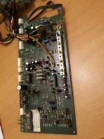
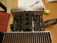
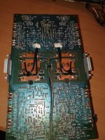
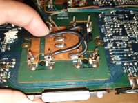
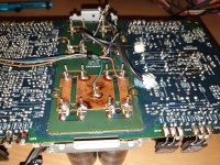
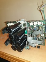
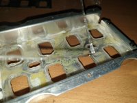
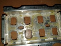
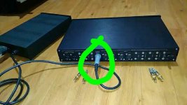
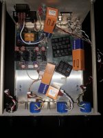
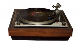
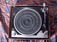
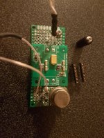
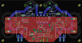
As my first complete LTspice -> KiCad -> PCB manufacture project I wanted to remake my damaged driver boards for a Sansui AU-999 integrated amp from the early 70's.
I wanted to see whether there are any circuit improvements I could implement into the new PCB and I wanted to ask you guys for a bit of help in trying to achieve this.

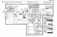
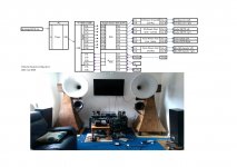
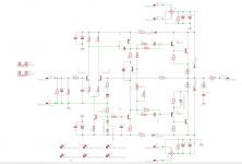
I'm attaching the original circuit schematic for the amplifier, the F-1159 outlined circuit is the driver board I was aiming to rework.

So far, the possible improvements I have identified are:

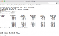
1. Adding a Baxandall diode to the quasi-complementary output stage - could someone advise on the best location? You can see I already attempted to implement this in my schematic, I tried different configurations and this one is giving me the lowest THD figure. It was done purely by experimentation and looking at other qusi-comp circuits.
2. Changing the value of output pull-off resistors from 220R to something smaller as suggested by @steveu in another thread - The suggested 47R seems to give a good improvement in THD and helps improve the x-over distortion
3. Adding a small value resistor in series with the 15pf feedback cap - steveu also suggested adding a small resistor (100R as starting value) to the feedback cap to prevent RF from getting into the LTP input transistor
4. Adding current limiting - suggested by the same user, what and how simple it would be to implement.
5. Improving the input differential pair - this is something I wanted to investigate, would adding a current mirror/source be a simple matter with the existing configuration?
6. Adding op-amp-based DC servo - this might be too much for this project as I would need to add step-down regulators to create a dedicated bi-polar PSU rail for the op-amp to operate, I'm not sure if that would be worth the effort?

I would be grateful for any additional suggestions or help with the above,
My knowledge is still very basic but so far I've learned quite a bit from this project and I really would like to see it completed.

I'm attaching the original amplifier schematic along with my LTspice files, inc. custom libraries.

Thanks for looking into this!!
Screen Shot 2022-07-08 at 11.55.45.png
Screen Shot 2022-07-09 at 11.32.42.png

Attachments

  • Screen Shot 2022-07-08 at 11.51.25.png
    Screen Shot 2022-07-08 at 11.51.25.png
    24.2 KB · Views: 488
  • Sansui AU-999.zip
    Sansui AU-999.zip
    4.3 MB · Views: 188

Thinking of building some sealed 15" subs, value thoughts on drivers

I currently has 1x18" and 3x12" subwoofers. and assembling a second sealed 18" sub. I am pretty happy with my bass and set up, hopefully happier still with 2x18"m and 3x12". In have two BMS 18N862 subs and 3 12" Sonus faber Cremona Subs

My thinking is I can sell on my Sonus Faber subs for probably over £1k each easily, they were £3k+ new and a very good hifi sub. However building a sealed 15" with a construction similar to the 18" I have built will be more rigid no doubt, plus I can increase the cone area by 60% and focus on speed and slam by using a lightweight 30 something Fs driver and targeting 35-80 Hz with a very efficient lighweight driver. The SF subs are designed to go low in a smaller enclosure and I dont need them to hit the lows as thats for my 18's primarily. I would value views on driver options so far I am thinking of something like the Faital Pro 15PR400, the SB Audience 150B350 or even the Eminence 1525 Legend. Internal volume will be something like 90L and made with 25mm Birch Ply, heavily braced. I have the amps, so its probably under £3k all in to build 3 depending on driver cost and the number of 25mm sheets required. So its more of a swap financially !!!

The cabinet will be 90L or so and a smaller version of this, my 18" unit in assembly.

45CD38B0-0E19-4669-8CC1-57F4402AC42D.jpeg

Motorola/Galvin 47b11 Capacitors

I have recently purchased a 40s battery powered 4 tube radio, Well, The chassis without the box. I would very much like to recap it, But I dont know enough about electrical engineering to make out the rating on the paper capacitors and translate them to modern values. I know not to touch the micas. It seems to be an all dc radio with no means of accepting an ac input.
The tubes are:
1A7GT Oscillator
1N5GT IF Amplifier
1H5GT audio demodulator/ first audio stage
and finally a 3Q5GT as the power amp.
The radio wants two voltages in, a 90v 12ma max tap for B+, and 1.5v .25a amp to the filament voltage or A+. With a stated max output of 250mw to a 3.2 ohm voice coil in a permanent magnet speaker.
The datasheet I found states it has 12 capacitors, most of which are paper.
C-1 Paper .1mf 200v
C-2 Paper .05mf 400v
C-3 Variable tuning cap (do these go bad?)
C-4 Paper .01mf 400v
C-5 Paper .01mf 400v
C-6 Mica 100mmf 500v (This one is most likely fine because mica)
C-7 Paper .002mf 400v
C-8 Paper .005mf 600v
C-9 Mica 100mmf 500v (another mica to not touch)
C-10 Electrolytic 10mfd 150v
C-11 Paper .005mf 600v
C-12 Paper .5mf
As far I I am able to wrap my head around the mfd is analogous to the ever present µF that seemingly everything these days uses in abundance, the mmf ratings listed are somewhat irrelevant because mica caps dont really go bad, well, Sometimes they do as is with everything eventually, But it is somewhat rare.
So my main question here is how do I read the values of the paper capacitors, and what do I replace them with? This isnt the only tube project I have, but it is the first I feel comfortable actually tackling, seeing as how the voltages are "Relatively" low.
s-l1600.png

RH84 power supply

Hello all:
I am making an RH84 version2. I have a question about my power supply.

I am attempting to salvage a used transformer for the B+. This transformer has multiple windings. The B+ winding is 630vac with no centre tap. My target voltage is +- 315vdc. I have read from the hammond site I should expect ~ 45% of AC with lots of ripple from a halfwave rectifer. So I thought this would work and have room for smoothing.
I am trying to use a beautiful 5U4gb I have in a nice ST bottle as the rectifier. For some reason I get 500+ volts DC.

I have one leg of the transformer going to both pins 4 and 6 of the rectifer. The other leg is (-). The heater transformer is connected to pins 2/8 and floating with CT not connected. B+ is drawn from pin2 into 35uF>13ohm>330uF with a 220kohm bleeder. B+ went up to +- 530vdc before I shut it down, I did not wait for it to stabilize as I am using 400v caps. Next I put a pair of 5408 diodes between the transformer and the rectifier thinking it would help, same result?

I am perplexed with what to do? or what I did wrong? Is the problem with using the 5u4 as it is directly heated? Any thought would be helpful.

Note:
I am pretty new at this so try to be gentle with your comments

I have already completed the chassis work. (I got a bit ahead of myself with that one. It looks really nice by the way.)

I am hopeful this can be sorted out with a little help.

Thanks in advance

Low Noise OPAMP NJM2122 is a new shining star

I was doing some noise measurements with OPAmp available on a market, and discovered that NJM2122 beats up any other OPA that I tryed to evaluate.
I mostly interested in low frequency end, even in 0.1-10Hz for methrological purposes (oscilloscope pictures), but it doesn't make difference - spectrum is the same up to 20 kHz and above.
Have a look:NJM2122.JPGNJM2068.JPGOPA1611.JPGNE5534_b.JPGNJM2122_2068_Y.pngSE5532_1.pngLM833.png
  • Like
Reactions: kipman725

A question for Sound Technology ST1000A owners?

Hey all-

I've got a ST1000A but it's been forever since I used it. I need to fabricate a new 'detector probe' - does anyone know the ST recommended design? I have not found it.

I made this one yesterday from a drawing I found in an unrelated document - no joy. Thanks for any input you have!

Attachments

  • detector probe.jpg
    detector probe.jpg
    59.9 KB · Views: 133

FS Mezmerize B1 buffer

FS Mezmerize B1 buffer

I'm going in a different direction so am selling this B1, it's 99% built with matched jfets purchased from the diyaudio store, all it needs are the fets ( included ) installing a volume pot, transformer and it wiring up. I will include the recommended Lorkin selector switch and optional heatsinks.

£120 plus postage at cost anywhere in the world

Attachments

  • 20221108_131636.jpg
    20221108_131636.jpg
    670.4 KB · Views: 214

loudspeaker distortions measurement in matlab

Dear DIYers,

I have developed a system identification /adaptive filtering approach FSAF, which (R2.0) is capable of speaker measurements using any excitation, such as music.

The main advantage over MLS/chirp is that FSAF linearises the loudspeakers at the true working area on real signal, and produces a non-LTI (Linear Time-Invariant) residual which you can examine both visually and aurally (.wav) in "fine print".

Here is ADAM F5 on 1 min from Mozart Piano Concerto, at 80dBSPL@1m:
aoTX80dBC50cm-mzrt-5.png


aoTX80dBC50cm-mzrt-6.png


https://www.mathworks.com/matlabcentral/fileexchange/83363-fast-subband-adaptive-filtering-fsaf
You'll need to read fsaf.4.pdf chapter 3 for spkid.m methods descriptions.
The same chapter also contains comparisons with old MLS / chirp methods.
You don't need to understand the underlying math to run the spkid.m class functions.
The license for FSAF is GPL.
The home version of Matlab costs $75, plus sigpro toolbox.
You may be able to run the spkid.m in Octave with some modifications (I have not tried it).

Hope it helps,
MZ

PVA glue and Evo-Stik Wood Adhesive - what is the difference?

What is the difference between generic PVA glue and Evo-Stik Resin W Extra Fast Interior Wood Adhesive?

I get the impression that PVA glue is more "watery" than Evo-Stik and it is certainly cheaper but is it better / worse, more or less suitable for speaker cabinet building? Since it is more watery I guess that PVA glue may spread better? Evo-Stik is water soluble before setting, can it be "diluted" before use?

Also, many speaker cabinet DIY instructions strongly advise you to use PVA glue, some advise you to "glue and screw" - should one just glue or glue and screw? Would screwing distort / buckle panels or battens?


EDITED - Just answered my first question (LINK):
Q: Is your wood adhesive based on PVA?
A: Yes, both Wood Adhesive Extra Fast (Resin W) and Evo-Stik Wood Adhesive Weatherproof are based on modified PVA emulsions

I am still curious as to whether one can "water down" Evo-Stik and whether one should "glue and clamp" or "glue and screw"?

  • Locked
Power cables. How much copper is too much copper?

So I've been having fun building some braided power cables recently after listening to Paul 'PS' McGowan extolling the virtues of a good braided cable. He's right, the braid mitigates/reduces RF.

For one of the cables I'm using Lapp ÖLFLEX CLASSIC 110 CY 3G (1,5mm² DIA) in a 3 cable-run braid geometry and combining the individual conductors in each run into a single one to give an overall conductor diameter of 4,5mm².
Why waste any copper by only using a single conductor from each run, right? Or wrong? Is this going to facilitate too much current draw and cause any issues? I'm assuming not and that conversly, having too thin conductors would cause issues, especially if used for hungry amps etc.

i.e. I suppose I'm looking for a confirmation that there are no disbenefits to combining all the conductors into a single thick conductor for each pin of a power cord.
I'm also using a slightly thinner gauge cable for a different model giving an overall 2.25mm² diameter for each conductor.
Thoughts?


Some pics.

This is the cable with 4,5mm² dia conductors.

Silkworm 02_1.png

Silkworm 01_1.png

Silkworm 03_1.png


This is the cable using slightly smaller 2.25mm² dia conductors.

01_1.JPG

15_1.JPG

For Sale Pulsar clock 49.152 MHz / dual LT3045 reg.

Pictures are showing what's for sale.

Price: 250usd / euro

Location: Sweden

Best regards. Bengt Dahlberg

PM if interessted 😎

Edit: I finally found all documentation that came with it as well. 🙂

Edit again: Dropped the price at another site to 250usd, same here as well of cource.

Attachments

  • pulsar clock 49.152.jpg
    pulsar clock 49.152.jpg
    512.7 KB · Views: 121
  • pulsar clock 49.152_2.jpg
    pulsar clock 49.152_2.jpg
    298.3 KB · Views: 129
  • pulsar clock 49.152_3.jpg
    pulsar clock 49.152_3.jpg
    416.3 KB · Views: 117

What are the acoustic principles behind a Karlson/Karlsonator speaker?

I am building a Karlsonator 8 with fostex fe206en at the moment. I read many articles and threads discussing the benefits and drawbacks of this design and discussing the suitability of certain drivers. But I am still not sure I understand how it works.

Am I correct in my understanding that it is a double bass reflex with a front chamber with an aperture that functions as an acoustical lens that improves off axis listening.

Am I right or wrong....or partially right but are there more acoustical principles at work?

NAP140/NCC200 Clone with PSU

NAP140/NCC200 clone with onboard PSU.

Clone of NCC200, but without output inductor.

Schematic doesnt contain the correct values yet and not all the caps/transistors are the right ones. But I wanted to get most of the layout done first to get a feel of the size of it.

Size is about 22 x 12 CM.

Attachments

  • NAP140-NCC200 clone_BRD.png
    NAP140-NCC200 clone_BRD.png
    184 KB · Views: 2,319
  • NAP140-NCC200 clone_SCH.png
    NAP140-NCC200 clone_SCH.png
    56.2 KB · Views: 2,327

Mark audio Pluvia 7PHD After 150 hrs

I Just want to express my gratitude for how great this driver plays into my TL that was designed for eikona. Time ago eikona was replaced by tang band and now with Pluvia. Not designed for the pluvia but i am speachless how good It Is developing in terms of nuances and delicacy.i use them for vocals+Guitar music and i dont Remember a driver giving me such a pleasure .next week a wood builder Will delivery a pencil speaker to accomodate maop 11.2.
Not sure It can sound Better thanx this pluvia but Hope Is high.only then i Will know if the actual pleasure come from the special voicing of the pluvia (jazzy?) or what..Will report back of course...enjoy and as a disclaimer i am not connected at all with MA team
  • Like
Reactions: LeifB60

Yamaha A-S501 vs Marantz PM6007 vs ...

Hy,
I'm looking to buy new amplifier for living room (around 20m2).
Currently I have a pair of old Pioneer CS-770 speakers, those will also be replaced a bit later, so they dont play a big role. But I will likely get something in similar size and power rating.
I listen mostly 80s & 90s rock, hard rock, pop. I used to listen to alot of electronic music, but as I'm getting older I'm moving away from it. But I still do like to shake the house from time to time.
This will be my first newer quality amplifier and I'm not sure what to expect. I want rich sound and bass cannot be sacrificed.

I'm looking at Yamaha A-S501 and Marantz PM6007. I'm also open to any other suggestions in this price range, but I must see if I can get it localy.

I like the looks of Yamaha better, but that is it for now...
I know nothing will be "the best of the best" in this price range, but I would like to hear opinions.

Thank you

Modding the SMSL SA-36A Pro

So I just got my SA-36 but it's the TDA7492PE version.
I opened it and it has 2 4400uf 16v capacitors. Would there be any benefit in swapping them for 2 4400uf 25v ones? And can I have those 2 and add a 2200uf 25v extra?
I'm currently using a laptop power brick 19v 3.41A but I'm guessing it's not delivering all of the power. The chip is supposed to handle up to 26v.

Will post pictures of the replacements I bought.

THAM 21, stupid idea?

Hi all,

I'm busy designing a subwoofer to be used at the scuba diving team "watering hole" clubhouse. It's a fixed installation with 4x JBL EON712's used as tops. I have space to fit 1 sub of about 1x1x0,7m. Normally this is used for background music, but we also have parties about 5-6 / year. Total floor area is about 80m2, total volume is about 240m3.

For now I have a 500W amp and plenty of DSP (DEQ2496) available to drive this.

I was looking at the THAM 18 and just for fun I decided to scale it up by 1.167X and sim it with the Beyma 21QLEX1600fe. Sims look really good to me.
Is this a totally stupid idea / am I missing something. Or could this be the sub to really pressurise the room if we want to?

Any toughts appriciated!

Attachments

  • Acoustical power.jpg
    Acoustical power.jpg
    47.7 KB · Views: 288
  • Input parameters.jpg
    Input parameters.jpg
    63.9 KB · Views: 236
  • Schematic diagram.jpg
    Schematic diagram.jpg
    32.6 KB · Views: 257

Welborne Squeezebox Power Supply Schematic Or PCB Needed

Greetings all. A good friend had this Welborne Labs 5v Squeezebox PS kit laying around and asked me to assemble it. The kit appears to have all the correct parts, including transformer, for the Squeezebox 5v power supply but the board supplied is incorrect. The supplied PCB is too small for the supplied components and the enclosure. I searched for Welborne labs squeezebox schematic but nothing popped. I was thinking of getting a board made or doing point to point. There is not much room under the board so a PCB would be the best solution with supplied enclosure. Any suggestions?

I attached pics of the kit with incorrect board and an assembled squeezebox PS pic snagged from the internet. Welborne labs is long gone so no help from them.

Thx.

Attachments

  • 20221108_104736.jpg
    20221108_104736.jpg
    301.1 KB · Views: 159
  • wb3.jpg
    wb3.jpg
    81.5 KB · Views: 156

Pictures of rebuild, recapped and refurbished Onkyo M-508 power amplifier.

I am uploading pictures of my rebuild, recapped and refurbished Onkyo M-508 power amplifier.

Attachments

  • 20190907_194821.jpg
    20190907_194821.jpg
    473.7 KB · Views: 244
  • 20190907_214649.jpg
    20190907_214649.jpg
    504.6 KB · Views: 228
  • 20190907_214652.jpg
    20190907_214652.jpg
    459.1 KB · Views: 216
  • 20190907_224735.jpg
    20190907_224735.jpg
    467.7 KB · Views: 228
  • 20190907_125423.jpg
    20190907_125423.jpg
    291.2 KB · Views: 215
  • 20190907_130057.jpg
    20190907_130057.jpg
    334.4 KB · Views: 211
  • 20190907_130101.jpg
    20190907_130101.jpg
    288.2 KB · Views: 213
  • 20190907_130417.jpg
    20190907_130417.jpg
    370.1 KB · Views: 216
  • 20190907_133051.jpg
    20190907_133051.jpg
    371.3 KB · Views: 217
  • 20190908_005803.jpg
    20190908_005803.jpg
    378.5 KB · Views: 220
  • 20190918_135616.jpg
    20190918_135616.jpg
    658.6 KB · Views: 241
  • 20190918_141145.jpg
    20190918_141145.jpg
    522 KB · Views: 220
  • 20190918_173657.jpg
    20190918_173657.jpg
    661.3 KB · Views: 226
  • 20190918_175904.jpg
    20190918_175904.jpg
    465.1 KB · Views: 227
  • 20191018_211107.jpg
    20191018_211107.jpg
    452 KB · Views: 227
  • 20191018_211113.jpg
    20191018_211113.jpg
    550.1 KB · Views: 207

Onkyo Grand Integra M-508 power amplifier rebuilding

Hello guys,

I am new to this forum and i personally found this forum very helpful and helpful people.

I am rebuilding recaping my onkyo grand integra m-508 power amplifier. I have already replaced main 8 filter power capacitors with 100 volts 10000uf cornell dublier capacitors. All other capacitors i bought are elna silmic ii nichicon fine gold nichicon muse and Panasonic fm.
I want to know that originally at c413-c416 there is nichicon muse 16v/10uf polarized caps and these muse caps are not available anymore only nichicon muse es bipolar are available in that value so i bought nichicon muse es bipolar caps instead of polarized capacitors. Can you people help me telling can i use bipolar nichicon muse es caps in that place instead of polarised?

My other question is can i replace c463-c466 polarized 3.3uf 50volts electrolytic caps with wima film caps?

Picture added of factory fitted nichicon muse polarized capacitor (green ones)

Help will be highly appreciated.
Thanks

Attachments

  • 20200412_035122.jpg
    20200412_035122.jpg
    999.9 KB · Views: 666

Guidance for adding tweeter to MJK open baffle speaker original version

I recently built MJK's OB speaker and am interested in adding a tweeter. I used the Eminence Alpha 15 A and the Fostex FE108EZ. I have a set of Tymphany BC25SC55-03 1" square frame tweeter from another project that I temporarily hooked in series to the full range driver just to see how this would impact the sound. There is no question that having this pointed to the ceiling added to the top end. That was a quick test and I removed the tweeter. I am hoping others have done something similar and can share with me the tweeter and crossover they used.

For Sale Little Bear T7 Tube buffer/RIAA preamp NIB

New in the box Little Bear T7 Tube buffer/RIAA preamp. My brother purchased this, but then traded it to me for a modified NAD integrated amp. I was going to mod it, but never got around to doing it, Totally new, stock, never even listened to. Some time along the way I lost the owners manual.

Prefer CONUS sale.

Asking $39.00 plus shipping.

LittleBearinside1.jpgLittleBearinside.jpgLittleBearSide.jpg

Icepower 50asx2 no sound

Firts of all i just wanna say hello everyone.


Im confused this class d amp icepower 50asx2 no signal/no output. When i use multitester on speaker out then tap input pin there is signal. But when speaker connected no response. I try to bypass L100 inductor no luck same issue. Is there someone experience this issue.

Thanks and advance.

Attachments

  • 20221024_195201.jpg
    20221024_195201.jpg
    437.4 KB · Views: 219

AKAI GX77 slow wind problem

There is a "big issue " about this reel many complain about the same problem which is slow RW and FFW when you wind the tape on any side the "engine" runs out of steam and often stops completely Obviously at this condition or even with less tape loaded between the reels starting RW or FFW respectively has also no effect Engine dont have the power to start.

Many post questions about it, and looks like a design flaw rather than a damage Still there is an other internet urban legend regarding a couple of resistors that fail (never found one failed though ) but of course winding problem has absolutely nothing to do with it .Yet again no matter the plenty questions or the urban legend nobody seems to come up with a solution .

I dont understand why this is happening on the internet . People that have no idea about electronics post solutions related to the blue resistors that obviously have no effect one the specific problem .

Anyone with ABC knowledge of electronics will see in the first minute that the blue resistor with one 1N 400X diode is there to consume the reverse voltage produced by the motor when spins free on the opposite direction . you don't want this reverse voltage against your drive transistors ...Alike protection diodes for reverse current to any transistor operated relay drive circuit .
You might have issues there but none of them is related to the slow REW or FFW problem . period !!!


Face it !!! the design has a flaw ...

Real reasons that might cause the problem
---Dirt and tape left overs all over
---Age problems regarding capacitors/resistors/contacts on the psu of 18.7 volts
---Aging of the motors
---Fatigue on the plastic gear ( created by spinning belts)
---Problems on the belts
---Tape/reel itself related issues
---Remote but possible: alignment issues
---In general and even though the design looks pretty cool problem remains that tape travels through a lot of barriers to end up in the other reel and that on its own is an issue .

Now you may choose any of the problems and any possible combination between them and you will end up with a slow wind speed ...Often its so slow that either the tape will stop completely winding at some point at the end, or if needed to start winding while some amount of tape is winded in the other reel then start is impossible .

There is a vanished guy that offers a fix but as far as i know this guy doesn't answer email or takes too long to ship parts or what he calls kit ....

Got it fixed permanently !!!
The way i did it offers

---No more than 5 euro of parts and one hour of work
---Increases wind speed side to side by far
---Reduces stress on belts and plastic gear
---Will work the same well even if belts inside are very loose/old
--- will be able to start in very high speed at any position of tape or type of load
---It will work extremely very well even if tape drive is dirty or belts are old or power supply has age issues or motors have age issues

Most of all has absolutely no side effects either in electromechanical points or from any sound or any other aspect ...

Kind regards
Sakis

Cambridge Audio Azur 840A V1 shut off.

Hello.
I bought a cheap Cambridge Audio Azur 840A amplifier. It goes off by itself between 2 and 15 minutes. CAP5 system says nothing.
In factory service menu all counters is OK.
I opened the amp and there are two capacitors C25 and C26 inflated a little.
Can it come from that?

Service manual

https://mega.nz/file/AThnRLIC#pw_XPcdZj1O5gSE7jPfl8sCsuQDRpYkN3DNUdBRpF3E

WTB (or trade): 1 x 2SD188 and/or 2SA627 BJTs

I'm repairing a Marantz 2220B for a friend with dead output transistors on one channel, which needs to be replaced.
Anyone willing to part with one of each for a good cause?

Again:
1x 2SD188
1x 2SA627

I'm buying or we can trade.

Trading.
I have tons and tons of new never used (stock) high end op amps + some discrete Melcor 1731 op amps, potted by yours truly. (photo attached)

Discrete Melcor 1731 op amp, with Mill-Max gold-plated pins. Potted.
AD797 - Ultralow distortion, ultralow noise single op amp. DIP-8.
AD8620 - Wide bandwidth dual precision JFET op amp. SOIC-8 or mounted on a DIP-8 adapter with gold-plated Mill-Max pins.
AD8610 - Wide bandwidth single precision JFET op amp. SOIC-8 or mounted on a DIP-8 adapter with gold-plated Mill-Max pins.
AD712 - High speed, precision dual Bi-FET op amp on DIP-8 adapter with gold-plated Mill-Max pins.
AD827 - High speed dual op amp. DIP-8.
AD845 - Fast precision CB-FET op amp. DIP-8
OP27 - Low noise precision op amp. DIP-8
+ Many many more. Write here or send PM if you got what I'm looking for!
  • Like
Reactions: wputera
Projects by fanatics, for fanatics
Get answers and advice for everyone wanting to learn the art of audio.
Join the Community
507,850
Members
7,890,716
Messages

Filter

Forum Statistics

Threads
406,370
Messages
7,890,716
Members
507,850
Latest member
saffer