Amplifier with Buzz & sensitivity at Line-IN - What to do?

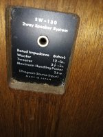
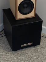
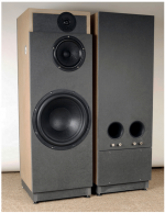
I have an issue with an active speaker: a B&O BeoLab 8000 with built-in amp.

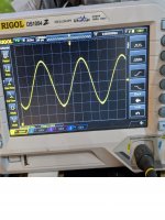
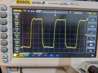
It has an RCA plug for line-in that I want to use. And it has an Auto stand-by function which means: the amp & speaker switch On when audio signal is coming in, and it (normally) switches Off/stand-by within 3 minutes after the audio signal has ended. I have a kind of distortion that causes buzzing noise. The noise is too loud for the amp to switch to Off permanently. It does try to switch Off, but it then immediately switches back On again, and then tries to switch Off gain. This process repeats continuously.

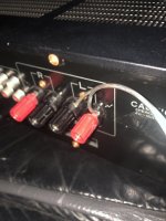
This happens both when I have nothing connected to the RCA connector for Line-in, as well as when I have an audio source connected to the Line-in. Though the buzz is a little bit less when I plug an iPhone as an audio source to the RCA line-in connector. But even with a source connected to the RCA, there still is a lot of sensitivity. Because when I touch the cable that connects the RCA connector to the AMP, it immediately switches On again.

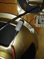
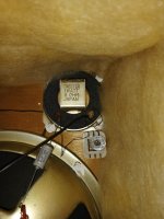
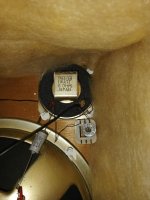
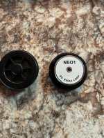
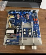
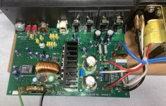
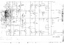
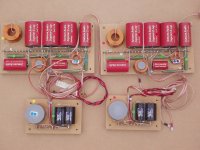
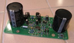
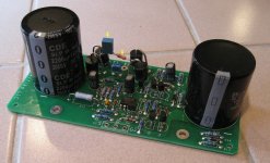
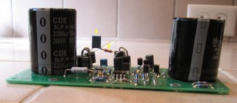
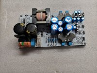
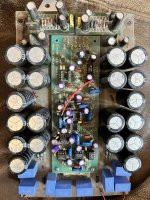
PCB with RCA Line-in connector: Left = bottom side, right = top side:

PCB05 - Top view Close-up.jpg
PCB05 - Dismantled.jpg


Next I put a 10K resistor across signal input & ground input. Without an audio source connected, it even increased the buzzing noise. With an audio source connected, the resistor makes no difference.

So I am confused, what is going on?
Anyone with help/suggestions/instructions?

Freshen up pair of AKAI SW-130 Loudspeakers

Hi All.
I acquired a pair of AKAI SW-130 Loudspeakers the other week.
They feature Japanese 12" Woofers, 3 1/2" Tweeters, iron core Inductors, & 4μF omats branded electrolytic capacitors.
These speakers have a reasonable sound.
I haven't removed to test the caps, but they are more than 50 years old.
Polypropylene would be nice, but is there a recommended electrolytic capacitor which could do the job at an economical price?
Also the fabric covering the baffles is marked and appearing a little tired.
Is there a fabric cleaner which is recommended?

Attachments

  • Akai Speakers 1.jpg
    Akai Speakers 1.jpg
    406 KB · Views: 1,133
  • Akai Speakers 2.jpg
    Akai Speakers 2.jpg
    417.1 KB · Views: 779
  • Akai Speakers 3.jpg
    Akai Speakers 3.jpg
    353.5 KB · Views: 540
  • Akai Speakers 4.jpg
    Akai Speakers 4.jpg
    444.8 KB · Views: 627
  • Akai Speakers 6.jpg
    Akai Speakers 6.jpg
    391.7 KB · Views: 575
  • Akai Speakers 10.jpg
    Akai Speakers 10.jpg
    408.6 KB · Views: 486
  • Akai Speakers 11.jpg
    Akai Speakers 11.jpg
    519.8 KB · Views: 756

Amount of hornloading in a Synergy horn

As the title suggests: how much hornloading can we expect a synergy to have for the sub 500hz frequencies? I guess it depends on the horn used?

I will be using a large biradial horn, with a 108x75cm (42,5"x29,5") mouth. I will be converting it into a 2-way with a 500hz crossover point, so off axis ports at 17cm (6,7"). I was planning on using 2x 15" drivers.

Question is:
- is there a ballpark estimation / rule of thumb to knowing how much hornloading this wooferpair will be able to get. Lets say over a 80-500hz range.
- Or should I model this? I'm not at home in all this software (like hornresp) so I dont really know how to do this.
- also, would this be a good range to use 18" drivers for? Or is this counterproductive?

Preamp recommended for Elekit TU-8800 SET Amp? Suggestions for my audio setup?

Did anyone try any preamp to pair with ELEKIT TU-8800? What's outcome? Worth the efforts or money? How about tube buffer (another rabbit hole or snake oil? LOL)?

My setup:
Digital source: Raspberry Pi 4B (running Volumio + Qobuz HiRes streaming & FLAC/DSD local files on a USB hard drive) + iancanada FIFO reclocker & HDMI I2S output
DAC: Denafrips PONTUS II using HDMI I2S input
Amp: Elekit TU 8800 SET tube amp with KT-88, transformer/resistor/pod upgrade, (still debating about the capacitor upgrade)
Speakers: DIY version of Decware ZF15L with Lii Audio F-15 drivers (https://www.decwareproducts.com/zms), plus a solid-state sub-woofer plate amp to drive a Lii Audio W-15 woofer driver to compensate for bass frequencies below 60Hz
Room size: Width 12 ft, Length 20 ft, Height 7ft
Room treatment: some DIY diffuser and absorber panels on 4 walls, floor is concrete with carpet, drop ceiling
Listening position: 4~5 ft from backwall
Speaker position: 4 ft from front wall, 1 ft from side walls

Listening Impression: with good recordings, I can hear wall of music coming towards me with instrument separations and some depth behind the speakers. The soundstage does not extend beyond the left or right of the speakers (except for 1 or 2 live concert songs). The vocal is at eye level (driver level), kind of low for me. Just wondering if there is any room for improvement and how.

Thanks for sharing your experience or thoughts in advance.

DIY project: acoustic upgrades to an existing speaker (horns & cabinet design)

Hello everybody: here I am to propose my first diy audio project. I am very intrigued in the acoustic amplification of sound and want to check out for myself if I can make an upgrade to a system I already have. Some background information: I am an engineer-architecture student with good carpentry skills (furniture-making), a very basic knowledge about electronics and a low budget 🙂. I am equally concerned about the looks of the project as I am concerned about its performance (that's just how architects are... 🙂 ).
As I am on a low budget, I want to work with the things I already have in my posession
-Amplifier: American Audio VLP1500 2x500W RMS into 8 Ohm
-Equalizer: Behringer
-Speakers: JBL JRX125 passive speakers (2.5-way system; Frequency Range (-10 dB):2 35 Hz - 16 kHz; Frequency Response (±3 dB):2 45 Hz - 12 kHz)

So what I plan to do is upgrading this setup by only working on the cabinets (I will keep and use all drivers and the crossover), and I would want to do this by introducing acoustic horns into the cabinets. The JRX125 design is super basic, it is just the compression driver and woofers mounted in a hollow cabinet that fits al three.
Here are some things that I think you should know:
-size doesn't matter (I will make multiplex cabinets from scratch and they can be as big as they need to be)
-I have an equalizer so the system itself doesn't need to be tuned perfectly
-I want the system to be LOUD, not especially good sounding; the components I have available are not high quality so I don't expect them to be super loud or good sounding but I want to see how far I can take it with the cabinet design

The speakers are a 2-way, almost 3-way design; in the images I included a scheme of the crossover which is basically a HP filter @ 2kHz for the compression driver, a LP filter @ 2kHz for the first woofer and a LP filter @ about 350Hz for the second woofer (JBL doesn't give exact values in their spec sheet so I tested this just by hearing).
-the compression driver is a JBL 2412, 1" exit compression driver (mounted on a JBL Progressive Transition™ Waveguide)
-the woofers are both JBL M115-8A 15" woofers

So I think I would design this setup as a three-way system with
-one 15" JBL M115-8A woofer LP filtered at 350 for the bass cabinet
-one 15" JBL M115-8A woofer LP filtered at 2 kHz as a midbass cabinet
-the 1" JBL 2412 compression driver for the high notes
In the image in the attachment I suggest how this could look like (note: this is just a quick sketch I made on top of a cubo15 sketchup file, nothing serious), I have been inspired by DIY soundsystems for dub and reggae music as they also have to be cheap and loud with a lot of bass.

Now come my specific questions:
-BASS: can I just download a cabinet design for a 15" folded horn bass cabinet and use this for my M115 driver? https://freespeakerplans.com/plans offers these free building plans with some suggested drivers, I dont find any specifically made for my cheap driver so I would have to use a plan not specifically made for mine. If not, which values of my driver should I compare to the driver used in the example project? Could I lower the frequency output of my speakers by using a more efficient cabinet design than the standard 'dumb box'?
-MIDBASS: as the frequency of the second driver goes from about 40Hz up to 2kHz I was looking to make a frontloaded horn with bass-reflex, similar to that one of the ALTEC 816. Is this a good idea? By the way how comes that these front loaded horns partially cover the driver (see in picture)?
-HIGH: the JBL 2412 compression driver comes with a standard JBL Progressive Transition™ Waveguide, can I make an upgrade for this? Is there a DIY way or another waveguide that I could buy that would make the electricity-to-sound efficiency even higher than it is with the standard? A bigger waveguide, or an exponential horn? Maybe a multicell horn?

I hope my intentions are clear, any replies would be of great help!

Attachments

  • Schermafbeelding 2022-12-03 om 19.04.39.png
    Schermafbeelding 2022-12-03 om 19.04.39.png
    24.2 KB · Views: 212
  • 816A_1.jpg
    816A_1.jpg
    232 KB · Views: 196
  • JBL_JRX125.v1.pdf
    JBL_JRX125.v1.pdf
    174.2 KB · Views: 174
  • preview.jpg
    preview.jpg
    54.4 KB · Views: 175

How to control Peak LED sensitivity in this circuit?

Hello,
I got a fully working VU meter module from Tascam 112 tape deck.

Analog meters sensitivity can be controlled indenpendently by potentiometers R103/R203 and this settings does not affect the peak leds.
My question is how to change the peak leds sensitivity? For now they lights up when signal on input is about 0.480V. I want to be able to adjust it so they will light up on any other level, for example +3dB (1.094V).
My first shot was to manipulate with R107 and making it a bigger value. This negatively affects whole circuit sensitivity, which is not acceptable 🙁
Is there an easy way to do that? I assume the resistors R108 and R109 determines the input voltage for Q101 transistor (2SC6203F).

Here's the complete schematic diagram of the circuit.
Any help is appreciated 🙂
4593615600_1669985934.jpg

HP339A distortion analyser

I have managed to make a total donkey of myself and damage a HP339A distortion analyser that I have no documentation for. I inadvertently plugged it into 220V instead of 110V. Naturally the external fuse didn't blow before it damaged internal components. I live in Saudi Arabia so don't have a good repair shop here. The damaged components are diode bridges D301 and D302 and diodes D303 and D304. If someone has a parts list and ideally schematic I can access via PDF or via other internet means (or knows where I can find such information on line) I would be most grateful as I could then source bits for a repair. The parts don't have identifiable markings on them.
The instrument's owner will be coming back in 4 days and I'll be one dead donkey if it's not working.
Hoping someone can help ...EEE AWWW!:dunno:

Headphones

Hello to everyone!

I have just built up a very simple headphone amp with two NE5532. It works very well and I just would like to know ,

if I've made some cardinal faults in the schem, for example if I did some "Don'ts" or forgot some "Do's".

Please have a look at the attached schem and tell me what You think about it.

A little problem I have is the popping sound in the headphone when I turn on or off the power supply - especially when the positive and negative supply voltages don't raise or fall exactly at the same time.

Does anyone know a good way to avoid this?

Any hints would be appreciated!

Attachments

  • 418864E5-1EC0-4395-98B1-1DF62BD2844B.png
    418864E5-1EC0-4395-98B1-1DF62BD2844B.png
    3.1 KB · Views: 245

NAD 216 red protection problem

I'am using two NAD216 in bridge mode with soft clipping off, and one night one of my amps just turned off without any reason, just hade the tv on so there was no loud volume involved.


When i try to start the amp it never switches from red to green as it suppose to and the red protection lamp constantly lights.


I've scooped the internet for every clue but no really luck, iam no electrical engineer so what to measure and how isnt my strong side but soldering is more like me. So ive read up on the web and swapped a few parts but no luck so far.


Things i have changed are as follow...


R243, R244
R203, R204
R201, R202
R236, R238, R239
C218, C219
and the output realy RL 201

Attachments

  • leftchannel.PNG
    leftchannel.PNG
    340.7 KB · Views: 680
  • rightchannel.PNG
    rightchannel.PNG
    319.6 KB · Views: 672
  • powersupply.PNG
    powersupply.PNG
    310.9 KB · Views: 634
  • mains.PNG
    mains.PNG
    72.7 KB · Views: 660

For Sale Miscellaneous tubes, parts, bunch of sleeving

I have a bunch of stuff I don't need, including tubes, parts, and a bunch of spools of expandable sleeving of various sizes and types. They're currently listed on eBay, but I would be happy to entertain any offers. Pics can bee seen on eBay or I can send them if you want.

Matched pair NOS Mullard GZ37 CV378 rectifier tube WB (P3)

Full 500' spool - 1/2" PET expandable sleeving, white - Techflex FRN0.5TW

Partial 250' (~200’ remaining) spool - 1/2" nylon expandable sleeving, copper- Techflex NMN0.5CP

Partial 500' (~200’ remaining) spool - 3/8" nylon expandable sleeving, black- Techflex CCP0.38BK

Partial spool - ~50' 3/4" PET expandable sleeving, carbon - Techflex PTN0.75CB

Full 250' spool - 1/2" nylon expandable sleeving, silver- Techflex NMN0.50SV

Partial 500' spool (~250’ remaining) - 3/8" PET expandable sleeving, carbon - Techflex PTN0.38CB

Partial 250' spool (~200’ remaining) - 1/2" nylon expandable sleeving, silver- Techflex NMN0.50SV

Partial spool - ~100' 3/8" nylon expandable sleeving, blue - Techflex PTN0.38BL

Enormous 120V:120V toroidal isolation transformers, 2500VA and 5000VA, 50 pounds or more!

JBL PB10 Help - Transformer getting hot

The HT sub started to act crazy, it would work ok for a couple of hours, but then the bass would eventually disappear.
I pulled the amp out and noticed a pair of caps were swollen, replaced them easily with the same value and it started working again.
That was encouraging but soon noticed the transformer was getting hot, very hot and this plate amp wasn't even back in the enclosure; which is a sealed plastic box inside the speaker box. I left it out on purpose just in case of something like this.
Not a lot of components on the plate amp, and they all look in good shape.

Since the plate amp is not in the box, I didn't reconnect the LEDs - Con3a1

Would hate throwing it away, any hope with this?

Thanks for looking!

Attachments

  • PB10.jpg
    PB10.jpg
    500.9 KB · Views: 431
  • JBL.png
    JBL.png
    1.4 MB · Views: 239

Capacitor hardware sources

I‘ll appreciate help with finding clamps (at a good price) and “capacitor terminal screws“ at the Mouse where I usually get my parts.

1. Clamps for 13/8 multi-section capacitors (50+50 uF). I found these for a lot of money. https://www.mouser.com/ProductDetail/Cornell-Dubilier-CDE/125565-06?qs=0uhOF6wYX64NvonUFAHLJg==
Is it really priced at $8.10 for one clamp? Am I looking at the wrong type. Why are these so expensive?

2. I bought these caps at Mouser with screw terminal like that arrived without screws. I can’t seem to find them in the Mouser website. https://www.mouser.com/ProductDetail/80-ALS70A681DE500

Threshold CAS-1 Capacitors

See the attached schematics

I want to replace the tantalums as the Mr. Pass has suggested in some other topics discussing Threshold products.
In particular this amplifier has 2x 47uf/20v tantalum caps at the power stage, 1x 47uf/20v tantalum coupling cap at the line stage and not-sure-what-that-part-does stage 220uf/10v.

My plan is to use some well known caps such as elna silmic 2 but I am wondering if I can swap the input coupling cap for a better one - polypropylene film cap. 47uf film caps are really expensive, I wonder if I can replace it with lower nominal caps... For instance it does not have to be rated for such high voltage - 20v. If I am going to solder in a bipolar cap. I could do with 5v max - as far as I know the amp input sensitivity is bellow 2 volts.

What about its capacitance? My almost-non-existant electronics knowledge tells me that a cap and the input impedance form a high pass filter. I am not entirely sure what's the input impedance, but on some booklet I've seen it stating 75k. Hell, I believe we can agree that 10k would be the absolute minimum. With a 10k input impedance and 10 times lower capacitance 4.7uf cap I will have an f3 of ~4hz. And in case the impedance is actually 75k, f3 is even lower.

I am wondering if all this my rambling make any sense about swapping the input capacitor for a lower value polypropylene capacitor instead of maintaining the same nominal 47uf electrolytic.
Do you think it is safe to conduct this experiment in practice?
Thanks!

Attachments

  • CAS1.jpg
    CAS1.jpg
    372.1 KB · Views: 135

For Sale Richard Marsh Headphone amp Kit + power supply

==Sold==

Richard Marsh Headphone amp Kit by TechDIY. Board and complete kit of parts including matched parts as recommended by Mr Marsh. This is a kit to build the amp boards themselves.
Build/Info Thread
I will also provide the copy of Linear Audio article that I purchased.

Also, 4.17UV ultralow noise power supply regulator +-12/15V 1A from diyinhk.
Link to shop

Any reasonable offer accepted.

For Sale Tang Band W8-2145

Selling 1x pair of Tang Band W8-2145

Fullrange, 8" drivers

They have about 40hrs on them and are like new in the original packaging
Used to test an open baffle setup (which was great btw!). For people closeby the baffles are available free of charge (18mm baltic birch). Located in Eindhout, Belgium

SOLD

Will ship worldwide

Attachments

  • IMG_3119.jpeg
    IMG_3119.jpeg
    504 KB · Views: 199
  • IMG_3120.jpeg
    IMG_3120.jpeg
    395.3 KB · Views: 155
  • IMG_3121.jpeg
    IMG_3121.jpeg
    398.3 KB · Views: 151
  • IMG_3122.jpeg
    IMG_3122.jpeg
    321 KB · Views: 203

For Sale Sunvalley SV-EQ1616D for sale

Sunvalley adjustable equalization phono stage for sale; low hours. I bought this as a kit and assembled it but have decided to go another direction. A set of tubes will be included, not including a rectifier tube, but the pictured diode bridge will be included. Requires 120V wall voltage. I built this per spec except that I included some extra shielding around the head amp; this is easily removeable. This unit has the optional Vcap upgrade. Tube guards, which aren't in some of the pictures, will be included (I don't use them). Asking $1100; free shipping to the continental US, at cost elsewhere. This phono stage has fabulous reviews! Look them up!
DSC03677.JPG

DSC03676.JPG

DSC03663.JPG

DSC03672.JPG

DSC03673.JPG

DSC03674.JPG

IMG_20220901_204753.jpg

QUAD 303 bias diode question / mystery ??

Hi all.

Hope somebody can help.
I have a Quad 303 which was faulty but i've fixed the fault ( open cct resistor on one of the driver boards ) and I intend to make 2 new amplifier boards and PSU board from scratch with HQ components throughout. Im puzzled by the schematic for the 303 and the actual board ? - The schematic shows 4 diodes around transistors tr103 and 104, but the actual amplifier has only 2 diodes ? I havent as yet verified why there are only 2 diodes fitted , but I will trace the tracks - any ideas what s going on with just the 2 diodes. Thanks . attached is a portion of the schematic im talking about

Attachments

  • quad 303.jpg
    quad 303.jpg
    19.7 KB · Views: 144

MarkAudio CHP-90 mica + DDVP-12.5-ML [TQWT]

I installed CHP90 in a small TQWT.
CHP90 is high quality and powerful in all band.

Login to view embedded media

Attachments

  • CHP90-01.jpg
    CHP90-01.jpg
    90.4 KB · Views: 485
  • CHP90-02.jpg
    CHP90-02.jpg
    99.3 KB · Views: 611
  • CHP-90mica-01.jpg
    CHP-90mica-01.jpg
    111.9 KB · Views: 857
  • DDVP-12.5-ML-01.jpg
    DDVP-12.5-ML-01.jpg
    153 KB · Views: 945
  • DDVP-12.5-ML-02.jpg
    DDVP-12.5-ML-02.jpg
    95.3 KB · Views: 755
  • DDVP-12.5-ML-03.jpg
    DDVP-12.5-ML-03.jpg
    112.8 KB · Views: 562
  • easy-ladder-cable-05.jpg
    easy-ladder-cable-05.jpg
    138.8 KB · Views: 487

Is there anything better than Open Baffle woofers?

Made some quick and crude H frames with a pair of 15” subwoofers with a QTS of .47 And an Fs of 21hz. Low passed at 140hz to some Dayton 3.5” fullrangers in sealed boxes and the sound is simply incredible!…..I’ve never had bass so articulate…..stand up acoustic bass is just amazing and cello?…….woah. If it gets any better than this, somebody share please. Didn’t take any measurements but I can tell I’m getting firm response to 35hz.

What are some good example of baffle design to improve diffraction

I am looking for a few baffle designs to improve diffraction. Troels has a few good designs which I posted below. Avalon Acoustic is another good example and looks good too.
What are some of baffle designs you have used in your design to improve diffraction?

Here is an example from Troels which I also use in for my speakers.
ellam-flex-intro-3.jpg

Somewhat easier to do but probably not quite optimized.
An externally hosted image should be here but it was not working when we last tested it.


A classic from Avalon Acoustic (by the way anyone knows they still have a patent on this design?). Looks beautiful as well.
An externally hosted image should be here but it was not working when we last tested it.

Cheap Bluetooth adapter

I have a cheap Bluetooth adapter so that I can play my phone or laptop music on an older stereo.
A couple FYI:
1. You can plug a wired headphones into this gadget, but the bass is weak, probably due to small output capacitors. This is not a problem driving high impedance stereo inputs.
2. It died and I suspected CMOS latch-up, so I momentarily shorted the internal battery and sure enough, it came back to life.
https://i5.walmartimages.com/.../86b5cd16-24f3-4cd9-bfe9...

Like


Comment


Share

Adjust input signal in tube preamp, avoid distortion!

Hello friends! I have a schematic that a computer science professor designed for me (he doesn't know much about audio, he only works with computers). It is a system that goes between a Class D module and the output of an electric bass preamp, specifically an Ampeg SVP Pro, it has a volume and a control that mixes the output of both triodes.
The design sounds very good connected to a Class D Ice Power 125 ASX module, the triode used is a 6sn7 with modifiable filament voltage adjustment to be able to use 12sn7 as well. Unfortunately, the Professor is no longer with us (RIP) so I cannot ask him for help.

The problem with the design is that it distorts when an external Bass Preamp is connected to it, when there is too much signal, the whole distorts, not too much, but if the idea is to keep it as far away as possible, the important thing is a clean sound.
I am not an expert, but I do know how to read electronic schematics and draw them (although I still have a lot to learn)
Thank you very much. 🙂
Schematic Experiment.png

Yamaha MX-55 topology, any good ?

I was able to get a Yamaha MX-55, that the previous owner recently recapped it.
Is the MX-55 any good ? what type class is it ?

it was a expensive amp when it was released

https://audio-heritage.jp/YAMAHA/amp/mx-55.html


Here is the service manual and the numbers for distortion after refurbishment


upload_2022-11-20_10-16-32.png


upload_2022-11-19_17-11-21.png

upload_2022-11-19_17-12-22.png

Attachments

  • yamaha_mx-55xx.pdf
    yamaha_mx-55xx.pdf
    7.6 MB · Views: 202
  • upload_2022-11-20_10-16-32.png
    upload_2022-11-20_10-16-32.png
    3.8 KB · Views: 71

Newby question: Damping factor

I know a few things about damping factor but not enough... I know it makes your bass sound flabby, booooomy, slow, like it's getting in the way of the music that's coming because the damn woofer is still recovering. I know physically, bad damping is the amps inability to control the momentum of the speaker cone, to slow it when it needs slowing, right? So it's kind of like the brakes on a car?

Is bad damping factor caused because tubes are inherently easier to "turn on" than they are to "turn off" (non linear)? If tubes are slower to turn off than turn on I could see how that might make it better at making the speaker cone move than making the speaker cone slow down. Is that right? Or am I wrong on that. Some other fundamental cause?

What is the best method to improve damping factor in an amp design? And, how far can/should you take that method before you start to cause some other problem in the design, because everything is a compromise right.

Aurasound MR-12.4 / NS12-794-4A Repair

I recently stumbled upon a pair of Aurasound MR-12.4 subwoofers on eBay, new in box, for $300 including shipping. A fantastic price, I thought, for the NS12-794-4A's flamboyantly dressed twin.

I bought them, received them, and as promised, they were new in box. Unfortunately, all was not well with the subs.

Their coils were rubbing.

I removed the magnets and found that the plating on the neodymium magnets was bubbled on one, and bubbled/flaking on the other. I was able to remove the bad plating, but this left me with two problems:

1.) The magnets are neodymium/iron alloy. Without the plating, they will corrode/rust over time.

2.) The voice coil in one driver was scratched in several places by the flaking plating, resulting in shorting. Its coil reads 2.6 ohms instead of 3.5.

The seller was excellent about this, refunded me my money, and let me keep the subs. Needless to say, I want to try to repair them. So, I was hoping to do a little brainstorming with you all.

My initial ideas are to:

1.) Coat the exposed sides of the magnets with a high-heat primer, or maybe even a dielectric varnish to take care of any possible corrosion.

2.) Gently sand away the scratches on the damaged voice coil, and recoat it with varnish.

Anyone have any thoughts, concerns, or ideas? What would you try?

Pioneer RT-707 solenoid lube?

Hello,
I have a Pioneer RT-707 I picked up today. You have to push up on the roller for the solenoid to retract and hold tension on the tape. Once it is up it is fine and holds tension. You can pause it and play again and it seems to function okay. I haven't connected it to an amp yet.The seller said the solenoid needs to be lubed. I took the cover off and I don't really see what he is talking about. The solenoid seems to be free in it's armature. Thank you

Edit: The pinch roller solenoid is moving very slowly. If it's about 1/2 way up it will pinch fast enough. It moves slowly when it retracts and when it releases. I cleaned the old grease off where I could see it and put new on and no change

Edit2: I cleaned the grease off I put on there and lubed all the moving parts (5) related to the pinch roller solenoid with a very small amount of 3in1 oil. It is working fine today. The two arms on the bottom are difficult to get oil in. A very tiny amount and let it sit face up over night.

Here's a manual

This might help somebody so I will leave it up.

Attachments

  • !cid_a99f3336-c2f9-4fd9-b44b-c434acda3704@namprd20_prod_outlook.jpg
    !cid_a99f3336-c2f9-4fd9-b44b-c434acda3704@namprd20_prod_outlook.jpg
    699.3 KB · Views: 175

BWServerAmp04 battery base TWS power amplifier build

Hi everyone

It’s me Murasame Yui again
A DIYer that creating beautiful things is a bounden duty in Lifetime

It's been two years since I posted my last project due to the outbreak

My DIY BT5.0 headphone amplifier

And in the past two years
Many have lost loved ones and family and me too
It’s let me down for a long long time
But life still goes on

so based on the previous project
I designed a new power amplifier

The name is BWServerAmp04
D303ACC8-9EA3-4A83-9D3B-7A090A52ADE3.jpeg


It’s a true wireless (TWS) power amplifier can support all popular wireless format including
SBC / AAC / atpX LL / atpX HD / LDAC

It can also be used wired with a USB-B cable

And it's a battery power amplifier like the previous one
This time I use Toshiba SCiB 20Ah cell
16A04CEC-EB6B-41AF-909B-360A84BD2577.jpeg


Because the project took me for seven months and too much photo (Over 150 photos)
So I make a blog for this build

Due to my major job still super busy
These two years have been projects for many large data centers UPS including Google / Amazon

I will slowly add old articles later

This amplifier has invited to exhibit at the audio show on 12/10 Taipei/Taiwan
8FF67D40-2641-47B6-9A05-4C3542A7891B.jpeg


If you are interested in my project
Welcome to click below link to watch

https://www.murasameyui.net/


Stay safe and health
Wish you all have a good day

Arduino Star For Xmas Cheer

My Xmas start rises for every December. I found one on the WWW and created my own version with programmable LEDs, Arduino UNO, and a 5vdc, 6amp power supply. I don't like blinking LEDs. I prefer to issue a repeating red,green, blue pattern. Xmas decorations are not regulated ( and should not be) but some neighbors have a large inflatable Santa Claus that deflates in the morning.

Attachments

  • star1.png
    star1.png
    30.4 KB · Views: 92
  • star2.png
    star2.png
    45.2 KB · Views: 102

Troels Gravesen Fusion Speaker Crossovers For Sale

I have one set of assembled Troels crossovers for the Fusion project.
Kit supplied by Jantzen £898
Fully working as designed used for around 11 months.
Looking for £500 plus postage to UK only.

Attachments

  • PA300868 (2).JPG
    PA300868 (2).JPG
    401.7 KB · Views: 218
  • Screenshot 2022-11 Fusion.png
    Screenshot 2022-11 Fusion.png
    113.8 KB · Views: 189
  • Screenshot 2022-11-07 at 16-42-50 Fusion.png
    Screenshot 2022-11-07 at 16-42-50 Fusion.png
    72.8 KB · Views: 170
  • Screenshot 2022-11-08 at 10-48-59 Fusion.png
    Screenshot 2022-11-08 at 10-48-59 Fusion.png
    365.5 KB · Views: 214

Gamut D200i - anything to adjust?

I recently bought a used D200i and I wonder if it’s been “tweaked” with.
It’s fully functional but cooling fins are basically room temperature. As they look like they can take some heat it makes me curious.

Measuring input power to <60W. Manual states 100W idle. I’ve asked Gamut without any answer.

I found a schematic online supposed to be for D200 ( not i) which is attached. The only thing to adjust seems to be for dc-offset or is it for something else?

I would really appreciate if someone has a D200i schematic to share. A service manual even better of course 😊

Attachments

  • 4925A387-AC64-4D7C-B05E-AFBBEBB43CD2.jpeg
    4925A387-AC64-4D7C-B05E-AFBBEBB43CD2.jpeg
    211.3 KB · Views: 560
  • EC3829D5-C9E4-4CE6-B273-67041E015422.jpeg
    EC3829D5-C9E4-4CE6-B273-67041E015422.jpeg
    402.1 KB · Views: 387

measuring JFETs IDss

So I saw this post from Mr Pass

Get a 5 to 13 volt supply and a DC voltmeter. Connect the +V to the
Drain, connect the Gate and Source together to a 100 ohm resistor,
and connect the other lead of the resistor to ground.

Measure the voltage across the resistor, which gives the Idss. 1 volt
= 10 mA of current.

Try to measure all devices under the same conditions, temperature,
and duration of test.

I'm assuming this is for N-channel and to test for P-channel, I just need to reverse power supply polarity. Am I right?

Thanks

which software to design the audio speakers?

Hi everyone .
I have never designed and used software to build speaker cabinet so I have to start from scratch.
I don't even know exactly what it takes. from what I have read, software to do simulations and software with microphone to record the response after building the cabinet with the speakers, so that corrections can be made if necessary.
I cannot waste much time studying the user manual and therefore I ask you to indicate the simplest and most intuitive software possible together with a cheap but decent quality microphone.
bye thank you

A snubber for my Akitika GT-101 (2 x LM3886)

I thought other diyAudio members might be interested in the modification I made to my Akitika GT-101 power amp kit. I added a snubber on the Power Supply Unit PCBoard, to reduce/eliminate RF interference by damping out any transformer secondary ringing that may occur when the rectifier diodes turn off.

The GT-101's PSU board already includes capacitor C5 (0.01 uF) across the secondary; the snubber components I added are (0.15uF in series with 110 ohms) for 115VAC operation, or (0.15uF in series with 120 ohms) for 230VAC operation. These are shown in a dotted rectangle on the attached schematics, and are indicated by yellow arrows in the "After" photographs.

Measured scope waveforms using the "Quasimodo" test jig (link) are also attached. You can see that the transformer secondary is critically damped (zeta = 1.00) in the red traces, corresponding to 109 ohms and 120 ohms.

The GT-101 uses an Avel Lindberg Y236602 toroidal transformer. It is rated 230VA, has dual primaries for 115VAC / 230VAC operation, and dual 35V secondaries which the kit connects in series. This 70VAC is rectified, filtered, and then feeds a DC voltage regulator (rare in a chip amp) which applies +72VDC to the LM3886 ICs.

Hoping this is helpful,
-MJ

Attachments

  • BEFORE.JPG
    BEFORE.JPG
    568.9 KB · Views: 1,033
  • AFTER_1.JPG
    AFTER_1.JPG
    412.3 KB · Views: 1,095
  • AFTER_2.JPG
    AFTER_2.JPG
    420.2 KB · Views: 1,689
  • schematics.png
    schematics.png
    51.7 KB · Views: 1,057
  • Avel_USA.png
    Avel_USA.png
    78.5 KB · Views: 1,027
  • Avel_Europe.png
    Avel_Europe.png
    70.1 KB · Views: 489

Carver to Naim conversion

Hey all!
I have an old carver tfm-15 cb that is fried. The meters are still good, the transformer and power supply are still great but the amp board is cooked.
I'm thinking about gutting this thing and putting in a couple of Naim 140 boards. After some measurements it looks like it will fit with lots of room to spare. The heat sinks are plenty big enough and it should work out.
The question I have is about the transformer, the only literature I can find on the 140 boards is that it takes +/- 40 volts. My transformer puts out 40-0-40 and the psu bumps it up to 53-0-53 DC. Now I'm sure I'll have to replace the psu or at least tone it down. But does the Naim 140 take a rectified 40-0-40 or rectified 20-0-20?
can anyone help me out?
Thanks guys
mark H.
,

Help please, Musical Fidelity A1/MA50 one channel distorted after about 10 seconds

Hi,
I am working on rebuilding the musical fidelity MA50, same circuit as A1 with higher rail voltage.

After my rebuild, one channel is good, but the other channel suffered from distortion problem about 10 seconds after power on. I measured the voltages, found the problem the problem could be abnormal voltage drop on R5.

5FCFEB71-7F3C-4085-A6D0-7A626C7663C9.jpeg


As the schematics shows, r5 connects to emitter leg of TR1 and TR2. It measures about only 250mv and quickly dropped to 200mv or less. Compare to the other working channel, the voltage should be around 500-580mv. Voltage on R12 in the same channel voltage looks goods.

So I think the problem is bottom half of the circuit.

I think R5 voltage problem affected the wrong voltages on entire bottom half of transistors ( TR5, 6, 9)

I believe this is the source of the distortion.

My question is what determines the R5-TR1,2 voltage?

I measured almost the entire circuit check for wrong elements and connections, but can not find anything wrong. So I think its better to do some theoretical analysis based on what I found.

Thanks

Adding Volume Control / Bass Cut / Bright Switch to mono TPA3116D2

Hi all,

I'm making a guitar "pedal power amp" as a bit of an experiment after years of making Bluetooth speakers using the commonly available eBay class D boards.

For this project I'm looking at this XH-M542 board:

https://www.ebay.co.uk/itm/194520940446

I know it says 100w, and it likely isn't, but that doesn't matter. As long as I can get say 30w at least from a 24v/3a PSU, it'll be fine.

My first conundrum was adding a volume control. I can't remember which thread I read on here, but I arrived at a simple 10k log pot on the input. I think that was chosen as the input impedance of the amp is also 10k? I could be wrong.

My next hope is to be able to add a couple of extra switches to the pedal to give a couple more sound options.

I'm thinking a bass cut switch to roll off some low end and tighten up the sound a bit, and then a bright switch that allows some treble to pass the volume control when the volume is turned down. These are also called "treble bleed" circuits and are found on guitar volume controls a lot, as you may know.

So my question is what values will the components required need to be, and how they will be connected up in relation to the volume control.

Any help/suggestions will be most appreciated!

Jim

DIY TT parts?

I have a Sota that I am rebuilding, and got a new motor, controller and sub chassis spring kit.
Plus a new arm and arm board, and cart.

So I now have an old motor, and wall wort.
An old arm, and an old cart.

If I can find a bearing assembly that would be great. A magnetic levitation one would be even better.
Where does one find a source for this stuff?

(The ClearAudio importer said that they will not sell an upgrade MagLev spindle without a trade in of the old part.)
Basiically I want a TT for the shed or give to one of the kiddies.

I have access to a lathe to make a platter, so I can make it fit whatever bearing I might stumble upon..

Can I connect a 100w tweeter and a 5000w subwoofer to a passive crossover and turn the volume of the amplifier to it's power that's above 600w

What happens if I connect a 100w tweeter and a 5000w subwoofer to a passive crossover and turn the volume of the amplifier to it's power that's above 600w.

Will the tweeter blow?

Should I match the power of both tweeter and subwoofer to avoid this?

What any suggestions for me?

24 dB high pass filter layout question

Happy New-Year,

In all the on line calculators a passive24 dB high pass filter can be seen as two 12 dB serie filter and is always made the same way: first serie cap is always the littliest capacitance value then the second "hub" (cellule) has a bigger capacitance value.

Is there a reason why a designer may want to invert the two 12 dB "hubs" of a 24 dB filter by putting first the bigger capacitance value with its dedicated shunt voice-coil then the second "hub" that is usualy the first ?

A sim on a crossover filter soft is saying that is the same but is it ? Or there is reason to invert sometimes ? Parts precision after sorting out vis a vis of the low pass filter for instance, anything else ?

Advice for: amp + passive vs active speakers?

Hi all, audio newbie here looking for advice. I've found this forum to be genuinely helpful.

I want very good speakers for my gaming PC. I will also use my PC to stream netflix/music. I was planning on getting some sort of DAC device. Some helpful people here previously recommended active speakers (i.e., JBL LSR305). I'm open to those.

Another audio friend of mine recommended the Rotel A11 Tribute (link here). It's an integrated amplifier that goes for $800. Not cheap. I can afford it, but don't want to invest money in something I won't notice a major difference in. I'm not an audiophile, but want good sound for years to come.

I watched this youtube video by the cheapaudioman which listed numerous high quality speakers. Among them were the Sony SSCS5 (link here). The consensus seems to be that they are surprisingly great for their price point. My understanding is that these are passive speakers.

My audio friend said that having this amplifier will enhance the quality of the sound. My question is: by how much?

To summarize: Will I notice a major difference between a Rotel A11 Tribute with good passive speakers (i.e., Sony SSCS5) versus a good pair of powered speakers like the JBL LSR305? I would use some sort of USB DAC device with my PC for either of tehse.

I'm not an audiophile that can outline the pros and cons of what the amplifier adds. In other words, here am I considering spending $800 on a device that I don't know much about, and it's magnitudes higher in price than the speakers I'm interested in. This is why I wanted to hear from you guys regarding the value added by an amplifier.

Need help fixing my turntable set up

Hi,
I’ve had this turntable set up for a few years now and have recently ran into an issue I can’t seem to fix. The left speaker ports on two separate amps have started playing flawed audio whenever I plug them in. I know the issue isnt the cables or the speakers because they play perfect when I switch them to the right port. I also don’t think it’s the amps because I find it unlikely that the same port on two amps have suddenly stopped working properly.

Does anyone have any solutions I could try out.

Cheers.

Attachments

  • image.jpg
    image.jpg
    281.1 KB · Views: 160
  • image.jpg
    image.jpg
    292.8 KB · Views: 164

Failing Valves - Hot spot....

I am looking for some kind soul to advise on a suspect valve. To me it looks like heater is failing still working but I am not risking it. I dont want to have it fail and cause other probs. Right hand valve toasty on one filament.... On switch on there is a disconcerting spark (seemingly from valse but its so quick hard to tell). One filament is clearly heating but others not. I guess its time to replace (it is only 8 months old and light usage!). The valve circuit must be complete for it to light up at all so I guess there is a short of some sort. My instinct is just to replace (again). Am I right to just bin it?
IMG_7707.jpg

For Sale Heat sinks x 8 £40 ( uk )

8 used heat sinks
Sizes in photos

Sorry but they’re collection only as I simply don’t get the time to post/ship.

I’m in Buckinghamshire
You may want the other stuff that I’ve listed for free .

Attachments

  • 44047002-14A6-4BB6-954D-D96F5F4E5FE6.jpeg
    44047002-14A6-4BB6-954D-D96F5F4E5FE6.jpeg
    310.3 KB · Views: 102
  • 0684DC2D-0CF7-44C0-9472-25CBDC68FE2C.jpeg
    0684DC2D-0CF7-44C0-9472-25CBDC68FE2C.jpeg
    229.2 KB · Views: 101
  • FF43EF14-6DF9-4729-8AF9-E293E7276EB3.jpeg
    FF43EF14-6DF9-4729-8AF9-E293E7276EB3.jpeg
    276 KB · Views: 85
  • CE46C033-F3F7-4AB1-A156-1E3B8FD47A80.jpeg
    CE46C033-F3F7-4AB1-A156-1E3B8FD47A80.jpeg
    276.9 KB · Views: 92
  • 8F1E9FEF-5FAA-4D74-B802-7F72A38504D7.jpeg
    8F1E9FEF-5FAA-4D74-B802-7F72A38504D7.jpeg
    355.1 KB · Views: 104
  • 1A1988EB-967C-4D2B-B220-87A4CE42F1C7.jpeg
    1A1988EB-967C-4D2B-B220-87A4CE42F1C7.jpeg
    331.6 KB · Views: 110

Broadband diffuser integrated with bass absorber

Combined broadband volume diffusor and bass absorber

To be of real practical use, diffusers are wanted efficient over a broad frequency range and bass absorbers should (usually / often) only be wanted efficient in the low range. Mid and high frequencies are wanted scattered / diffused in the room, not absorbed creating a “dead sounding room”. A combination will require large width and depth. That combination can be accomplished with volumetric diffusers integrated into a deep bass absorber. If one has a long room and can spare the depth needed, both low bass modes can be treated while having a diffused “live” sound for mids and high frequencies. If one uses surround speakers / subs at the back wall, these can be integrated too.

In a document for Degree of Doctor of Philosophy at Salford University’s faculty for acoustics, Richard James Hughes presents his findings för Volume Diffusers in comparison to other type of diffusers like BAD, Schroeder, MLS etc. In short, the volume ones show better results. The paper is loaded with heavy math but it is not necessary to understand all that math, one gets by quite well from the text alone and the diagrams. The original paper is included and a “compilation” I made. In the paper "Geometric Shadow Zone and Back Scattering" is mentioned with a bunch of math. In the compilation some pictures for this is included. BADs aim for 50% reflecting areas and 50% absorbtive areas. Volume diffusers are based on a Golomb Ruler (google for explanation) and like BADs aim for a total of 50% reflecting area but for for 50% transparency (gaps between slats), seen from straight ahead. BADs have no temporal diffusion, volume diffusers have that. A bunch of identical Schroeder diffusers beside each other, forming a long total width, will give lobing. There will be no/less of lobing with volume diffusers. In short the volume diffuser consist of, say 5 layers / fences, behind each other. Each fence has a different slat width, narrowest at the front and widest at the back.

Negative about broadband volume diffusers with several layers:
They need to be large in length and depth.

Positive about broadband volume diffusers with several layers:
As they need to be large in length and deep, they are suitable to integrate with efficient bass absorbers and back wall speakers.
They are a lot easier / less time consuming to DIY with fewer and simple tools than say BADs, Schroeder or “skyline” diffusers.
If one wants to, one can integrate LED-strips for visual effects behind the slats.

Hughes gives a nice example for the construction of a complete volume diffuser to reach the wanted 50 % transparency and which has a broad range from 400 to 3378 Hz. I took that example and wrote an excel spread sheet from it. From the excel, one can to a certain amount customize other widths. Ideally: Start with total possible width, the 2 slats at the back should together form 1/3 of the diffuser width. Then keep the width ratios in the excel from back to front intact to keep 50% transparency. Check out carefully on the “drawing” where the slat should be positioned for 50% transparency. Example there are 3 slat 180 mm wide versus totalt width 1800 mm. It is quite easy to count 3x180 mm slats and 3 gaps with w= 180mm. As the chosen “N” = 10 x 180 mm = 1800 mm, it is easy to conclude that the largest gap in that “fence” is then 10-6 = 4x180 mm wide. One can chose other “N” depending on available width and depth. That will be a compromise and change the 50% transparency. If available width is small, the slats at the front will be very narrow with 5 “fences”. Diffusion at very high frequencies is quite useless unless you are a dog or a bat. I would use fewer fences in that case and skip the first at the front.

From some scrap wood I made some which are 70 cm wide x 30 cm deep x 120 cm high. I put some hinges on them so they can be swiveled sideways to have some control of where to steer the reflection in the room, towards listening position or towards side wall for longer delay time. (70 cm was a bit too wide, so I had to cut off a corner for a clearance vs the sub.)

The diffuser could start at about 600 mm above floor level and be 1-1,2 m high. Above and below and to the sides, there is place for bass absorbers. For integration with a good and efficient bass / slat absorber at the back wall I suggest to check out the thread at Gearspace: https://gearspace.com/board/studio-building-acoustics/1314238-different-helmholtz-slat-sizes.html and ostfisk’s video on Youtube: Login to view embedded media (very informative on details).

To open the excelfile Volume diffuser-Adhoc, change the ending to xls (I hope that will work)

Edit: No it didn't 🙁 Someone who knows how to fix that, so it can be used?

Attachments

  • Like
Reactions: Flaesh

For Sale FREE quality vintage capacitors and more (uk)

For collection Only in Buckinghamshire

A bunch of Philips, Rata , Ansar capacitors that all test at correct levels or very close .
Needless to say that I’m giving these away for someone to make use of and not just list for sale ( I could do that)

I will also throw in a bunch of induction coils and maybe more stuff like crimson audio boards etc.
1B2374F4-3618-490B-9703-B5CC1EBB7F3A.jpeg
53FC5346-AAD4-485F-B1A3-F5F50F60C135.jpeg

Attachments

  • D068730C-88B5-4312-B429-DB09E35FA0CC.jpeg
    D068730C-88B5-4312-B429-DB09E35FA0CC.jpeg
    485.9 KB · Views: 101
  • 5088F078-731D-4948-B40E-CA93D779C363.jpeg
    5088F078-731D-4948-B40E-CA93D779C363.jpeg
    686.2 KB · Views: 114

How do I match transistors? (Explained inside)

I have a balanced amp that's uses 2 P and N-channel JFETs per board.

The amp uses 4 boards in total.

How should I match the transistors?

  1. Do I match them per part label? (Example: Q5 is a P-channel part so I need a quad match for this part)
  2. Do I match for all the JFETs on the board? (example: Q5/6 are P-channel parts while Q7/8 are N-channel ones. I need a quad match for these 4.)

Changing the Rapsberry Pi Clocks?

Hello

im trying to figure out what impact the clocks of the raspberry pi 4 have and i wanna exchange them but i need a little help since im not too keen on electronics

there are 2 chinese hats i found which do the job:
http://home.teradak.com/products/118.html
https://www.thanksbuyer.com/ustars-...mv85-for-raspberry-pi-4b-change-crystal-73302

but im kinda wondering which would be the better approach
1. one 10mhz oxco master clock where the 25mhz and 54mhz clock signal are derived from for the raspberry pi
2. or seperat 25mhz/54mhz txco clocks

and im curious if i even need one of those boards, would it be easy to implement two txco clocks just by myself? do i even need additonal circuitry or can i power one of those txco clocks directly with 3,3 and just hook up the output to the clock input pad on the raspberry pi after i removed the existing clock? i actually dont think there is much needed circuitry wise beside maybe a few caps?

any help is much appreciated (as long it isnt "this doesnt matter" advice, i wanna test it myself 🙂 )

Greg Balls GB150D and SKpre documentation and schematics

Hi, I was looking for some documentation on a kit I got ahold of, the GB150D by Greg Ball.
Greg has closed down his online forum and thus removed the documentation, he also released the designs to the DIY comunity.
Or so I understand.
I got in contact with one of Gregs former coworkers and he scanned the documentation for the power amplifier "GB150D" and the pre amplifier "SKpre".
He is getting old and his health is deteriorating, so he asked me to see to it that those who need the documentation gets it.
He also assured me that Greg himself doesn't care.
I attached the documentation but bare in mind that the pages are not all in order and there could be a page or two missing.

So, any interest in doing something with it?

Quality audio from within Virtual Machines?

I'm planning to move my music-playing system from a failing laptop to a virtual machine instead. The exact configuration is yet to be decided, but the host system will be Linux running either QEMU/KVM or VirtualBox. The guest OS would 'preferably' be also Linux.. there are a few excellent windows applications that continually tempt me, so that might still be an option, but just personally I'm not keen on where windows is headed so am trying to get up to speed on Linux instead.

The output will be to a DAC or high-quality external sound-card (there is the option of an internal card but I've had bad experiences of noise when the analogue section is within a full-blown PC). It will probably be multi-channel, even though I only play stereo, in order to allow digital-software crossovers.

Anyway, I've not tried to run serious quality audio from within a virtual machine before, so am quite naive about it. It might be a complete non-issue, or conversely there could be all sorts of pitfalls that I'm not aware of - as the audio is sent from within to without. So please forgive my ignorance and if anyone has experience of this I'd appreciate any thoughts on what problems might be encountered or what measures might need to be taken (if any) etc.

Many Thanks,
Kev

Alpair 12P Small Reflex - The world's least popular FR speaker?

Hi everyone,

I'm currently using open baffles with 1 MarkAudio Alpair 12P and 2 Eminence Alpha 15a per side. The chipboard (these "prototypes" ended up serving me well for more than 2 years) was cut to closely mimic the dimensions of the Quad ESL. Add a MiniDSP and a pair of Quad 306: I like what I hear. Problem is depicted in image no. 3: They take up way too much space in my new, much smaller living room. 🙁

Since I already have and like the Alpair 12P, I thought about placing the woofers in storage and go with Scott's "Small Reflex" proposal. Hope it's OK to add the PDF. As far as I know it's been released to the DIY community, but somewhat hard to find on the web. Trouble is, nobody seems to use them. No matter if searching here or through Google, almost all results for Alpair 12P Small Reflex seem to refer to Abszero's build or his own blog entries about it. The only other (modified) build I found is that by shane h and his brother. I reckon the 12P is not loved by everybody here and in particular the low-end extension is not exactly its strong point, but is the Small Reflex really that bad? :ghost: If anybody has build them silently and in secret, please stand up and share your experience.

Strictly speaking, a 12P Pensil is taking up about the same space as the Small Reflex on its stands. But as alternative facts have become so popular lately, I have to say that the visual appearance is still heftier. Also the Pensil does not fit into my car, while the Small Reflex does. 😛

As far as cabinet construction goes: I'm tempted by the idea to go with 18mm plywood for the baffle and back only and make the other walls from 15mm or even 12mm plywood. With addition of one vertical and two horizontal braces (12mm ?) I feel like this could still be stiff enough compared to the small panel sizes to deal with. What do you think?

Thankful for any thoughts and comments. Even if it ends up to be "just try it yourself" or "go with SuperPensils" or "ditch all your lowly equipment".
Projects by fanatics, for fanatics
Get answers and advice for everyone wanting to learn the art of audio.
Join the Community
507,758
Members
7,887,178
Messages

Filter

Forum Statistics

Threads
406,169
Messages
7,887,178
Members
507,758
Latest member
Cindy